EP1073211A2 - Verfahren und Vorrichtung zur Kommunikation über elektrische Energieversorgungsleitungen - Google Patents
Verfahren und Vorrichtung zur Kommunikation über elektrische Energieversorgungsleitungen Download PDFInfo
- Publication number
- EP1073211A2 EP1073211A2 EP00114315A EP00114315A EP1073211A2 EP 1073211 A2 EP1073211 A2 EP 1073211A2 EP 00114315 A EP00114315 A EP 00114315A EP 00114315 A EP00114315 A EP 00114315A EP 1073211 A2 EP1073211 A2 EP 1073211A2
- Authority
- EP
- European Patent Office
- Prior art keywords
- modulation
- carrier signal
- type
- reprogramming
- supply network
- Prior art date
- Legal status (The legal status is an assumption and is not a legal conclusion. Google has not performed a legal analysis and makes no representation as to the accuracy of the status listed.)
- Granted
Links
Images
Classifications
-
- H—ELECTRICITY
- H04—ELECTRIC COMMUNICATION TECHNIQUE
- H04B—TRANSMISSION
- H04B3/00—Line transmission systems
- H04B3/54—Systems for transmission via power distribution lines
-
- H—ELECTRICITY
- H04—ELECTRIC COMMUNICATION TECHNIQUE
- H04B—TRANSMISSION
- H04B2203/00—Indexing scheme relating to line transmission systems
- H04B2203/54—Aspects of powerline communications not already covered by H04B3/54 and its subgroups
- H04B2203/5404—Methods of transmitting or receiving signals via power distribution lines
- H04B2203/5416—Methods of transmitting or receiving signals via power distribution lines by adding signals to the wave form of the power source
-
- H—ELECTRICITY
- H04—ELECTRIC COMMUNICATION TECHNIQUE
- H04B—TRANSMISSION
- H04B2203/00—Indexing scheme relating to line transmission systems
- H04B2203/54—Aspects of powerline communications not already covered by H04B3/54 and its subgroups
- H04B2203/5429—Applications for powerline communications
- H04B2203/5441—Wireless systems or telephone
-
- H—ELECTRICITY
- H04—ELECTRIC COMMUNICATION TECHNIQUE
- H04B—TRANSMISSION
- H04B2203/00—Indexing scheme relating to line transmission systems
- H04B2203/54—Aspects of powerline communications not already covered by H04B3/54 and its subgroups
- H04B2203/5429—Applications for powerline communications
- H04B2203/5445—Local network
-
- H—ELECTRICITY
- H04—ELECTRIC COMMUNICATION TECHNIQUE
- H04B—TRANSMISSION
- H04B2203/00—Indexing scheme relating to line transmission systems
- H04B2203/54—Aspects of powerline communications not already covered by H04B3/54 and its subgroups
- H04B2203/5462—Systems for power line communications
- H04B2203/5483—Systems for power line communications using coupling circuits
Definitions
- the invention relates to a method and an apparatus for Communication via the lines (Powerline) of the electrical Energy supply network.
- the inventors therefore have frequency ranges from 150 kHz, considered up to about 30 MHz or more. For these frequency ranges there are currently no standards or regulations in general, the permissible transmission level specifically for communication on the power grid. With a wide one Diffusion of devices covering this frequency range use, the risk increases that existing radio services, who work in the same frequency range with permission become.
- the frequency range from 0.15 to 30 MHz is currently occupied by a large number of radio services, each of which a small part of the frequency range is allocated.
- the operation of electronic devices that have approved radio services can generally interfere with the relevant regulatory authorities be banned for telecommunications.
- frequency ranges exist such radio services to the knowledge of the regulatory authority no longer or only very rarely used for communication via the energy supply network initially to release "conditionally". This means that the release is withdrawn can be as soon as a radio service in the corresponding Frequency range is disturbed.
- the invention is therefore based on the object of a method and to provide a device with which a quick Communication via the energy supply network efficiently is possible.
- the invention allows optimal use of resources of the energy supply network by reprogramming the device used for the transmission of information accordingly the availability of the network.
- the device therefore does not need to be replaced as a whole if for example, individual frequency ranges are no longer available stand because they interfere with other services or because they themselves are disturbed, or if individual frequency ranges are available have become because of a fault or other services no longer feel disturbed.
- a modulation and / or reprogrammed a demodulation device typically a modulation and / or reprogrammed a demodulation device.
- the determination of the availability of the energy supply network is advantageously based on a measurement of the Properties of one or more of its transmission channels. To ensure that reprogramming is still safe in response to a fault To be able to carry out the measuring and reprogramming advantageously with a robust, robust, insensitive to interference Modulation type carried out.
- the embodiment according to claim 3 has the advantage that reprogramming economically without separating the device from the energy supply network, especially without sending in to Manufacturer or customer service can take place. Conveniently adjusts the device by receiving a command signal Claim 7 a change in the availability of resources of the energy supply network. Sending out the command signal for example from the network operator Remote programming of the device. A practical realization the device is specified in claim 10.
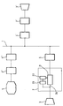
- the energy supply network 1 contains the low-voltage network in or outside the home or the medium voltage network.
- the energy supply network 1 is used for the transmission of data in the form of modulated signals between the terminals 3, 3 'and the operator 4 used.
- the interface 5, 5 ' serves 5 '' each of the separation of the modem 2, 2 ', 2' 'from the power supply network 1, so that the power supply voltages on the network 1 largely kept away from the modem 2, 2 ', 2' ' are modulated while those used for data transmission Signals are let through.
- the modulated signals are in one or more frequency bands in the range of 0.15 up to 30 MHz.
- the frequencies are in each frequency band one or more carrier signals (carrier frequencies) that in the modulation and demodulation circuit 21 with the digital Data are modulated.
- DMT-OFDM discrete multitone orthogonal frequency division multiplex
- CDMA Multi-carrier code division multiple access
- the modem 2, 2 ', 2' ' is set up so that the used frequency ranges changed at any time and as often as required can be. This is an adaptation to changed Frequency assignments easily possible.
- the modem 2, 2 ', 2' ' contains a rewritable memory implemented as an EEPROM 22 and a control unit 23 in the form of a microprocessor.
- the functions of the modem 2, 2 ', 2' 'described here can also with a DSP (digital signal processor) or with an ASIC (application specific integrated circuit) become.
- the memory 22 contains software data that the used by the modulation and demodulation circuit 21 Define carrier frequencies.
- the control unit 23 is both with the memory 22 as well as with an input / output connection 24 for the digital data of the modulation and
- the control unit 23 a command signal contained in the digital data received the modem in a programming mode offset by instructing the control unit 23 which in Memory 22 to change stored definition of the carrier frequencies, so that subsequently certain carrier frequencies are not continue or other carrier frequencies are used again.
- the modem 2 can be removed from the associated one Remotely program terminal 3 or from operator 4. The modem 2 can thus be reprogrammed in situ without to be sent to the manufacturer or customer service have to.
- the control unit 23 only speaks to the command signal if this is the respective modem 2, 2 ', 2' 'individually identifying, unique address. So everyone can Modems individually or several modems can work together, in groups be reprogrammed. Preferably the content of the memory 22 via the control unit 23 for the operator 4 or the associated terminal 3 can also be read out, so that its Content checked and reprogramming only carried out if necessary can be.
- the operator 4 can issue the command signal with or without prior approval of the user of the associated Terminal 3 are formed. Without the consent of the user can do this, for example, each time the user accesses a System provided by operator 4, for example an Internet connection provided by operator 4 respectively.
- the modem 2, 2 ', 2' 'instead via the energy supply network 1 also via an analog telephone line, an ISDN connection, via a connection to a Cable television network, via a radio link (for example GSM, DECT, W-CDMA, CDMA, Bluetooth), via an infrared connection, a computer interface (e.g. a serial or parallel interface, a USB or PCMCIA connection), via a digital data feed device (e.g. a CD, DVD or floppy drive), by exchange of the digital memory 22, which is then, for example, an EPROM is realized, or take place via another digital bus.
- a radio link for example GSM, DECT, W-CDMA, CDMA, Bluetooth
- a computer interface e.g. a serial or parallel interface, a USB or PCMCIA connection
- a digital data feed device e.g. a CD, DVD or floppy drive
- the operator 4 is an Internet service provider, for example, every time he accesses the Internet of the terminal 3 recognize that access from the modem 2 via the power supply network 1 and your own modem 2 '' is done. Then is sent to the control unit by means of command signals 23 the version of the software in the memory 22 is queried and, if necessary, automatically or with the consent of the user updated on the terminal 3.
- the operator 4 sends changed availability of the resources of the energy supply network 1 updated software for data transmission for example on a 3 1/2 '' diskette to its customers.
- the Terminal 3 represents a PC that the user connects to modem 2 connects. With the floppy disk and the PC, the user runs the Reprogramming of modem 2 by.
- the user changes his contract terms with the operator 4.
- his modem 2 for example to a higher data transmission speed, extended access rights for data transmission services, to a larger number through the power grid selectable and receivable as transmission medium TV channels or available on a changed selection Services such as games, feature films, etc. reprogrammed.
- the signal-to-noise ratio for information transfer the low-voltage grid through targeted measures such as shielding and filtering interference from individual consumers on Network improved, whereupon all modems 2, 2 '2' 'of the network remotely to a faster modulation type, for example switched from eight-fold QAM to sixty-four QAM become.
- the Control unit 23 of the modem 2 based on the error rate in the Transmission of data via the energy supply network 1 or by measuring other properties of the lines of the power supply network the transmission quality and stores information about it in memory 22. For example Properties such as attenuation of the network or lines in the frequency spectrum of interference signals measured and in a fault log saved.
- the operator 4 saves the saved Information is read out from time to time and used to reprogram the modem 2 so that the transmission quality is improved. This is done by sending the command signal to the modem, for example for deactivation of frequency ranges in which interferers occur and for Activate new frequency ranges in which little interference occur.
- the control unit 23 of the modem 2 then provides only based on a command signal from operator 4 that reprogramming is necessary.
- the control unit 23 itself determines that transmission errors gain or even get out of hand, and leads reprogramming based on the fault log itself on.
- the control unit 23 can reprogram itself make or the operator 4 the previously described Command signal request to reprogram after to carry out its instruction.
Landscapes
- Engineering & Computer Science (AREA)
- Power Engineering (AREA)
- Computer Networks & Wireless Communication (AREA)
- Signal Processing (AREA)
- Cable Transmission Systems, Equalization Of Radio And Reduction Of Echo (AREA)
- Near-Field Transmission Systems (AREA)
- Small-Scale Networks (AREA)
- Dc Digital Transmission (AREA)
- Communication Control (AREA)
- Coupling Device And Connection With Printed Circuit (AREA)
Abstract
Description
- die Lage einer oder mehrerer Trägerfrequenzen neu festgelegt,
- die Modulationsart, beispielsweise das Modulationsverfahren, der Modulationsgrad oder Modulationsindex geändert,
- die Amplitude einzelner oder aller Trägersignale neu festgelegt,
- bei einer mikroprozessorgesteuerten Modulations- oder Demodulationseinrichtung ein Teil oder die gesamte Software für den Mikroprozessor ausgetauscht,
- der Frequenzgang digitaler Filter in der Modulations- oder Demodulationseinrichtung neu festgelegt,
- die Datenübertragungsgeschwindigkeit neu festgelegt,
- die Datenübertragungsrichtung für einzelne oder alle Trägersignale neu festgelegt,
- Funktionen der Modulations- oder Demodulationseinrichtung, die einen Einfluß auf die Nutzung von Ressourcen des Energieversorgungsnetzes als Übertragungsmedium haben, geändert,
- Berechtigungen zur Kommunikation mit bestimmten Gegenstellen, die beispielsweise aufgrund der örtlichen Lage oder verwendeten Trägerfrequenzen zu Störungen Dritter fuhren, neu festgelegt, und/oder
- die Modulations- oder Demodulationseinrichtung für bestimmte Zeiten oder insgesamt gesperrt oder entsperrt.
Claims (11)
- Verfahren zur Übertragung von Informationen mittels einer Übertragungsvorrichtung (2) über das Energieversorgungsnetz (1), mit folgenden Schritten:Festlegen eines Trägersignals und einer Modulationsart,Modulieren des festgelegten Trägersignals mit den zu übertragenden Informationen gemäß der festgelegten Modulationsart,Übertragen des modulierten Signals über das Energieversorgungsnetz (1),Feststellen der Verfügbarkeit des Energieversorgungsnetzes für ein moduliertes Signal,Umprogrammieren der Vorrichtung (2) entsprechend der festgestellten Verfügbarkeit, undFortsetzen der Modulations- und Übertragungsschritte mit der umprogrammierten Vorrichtung (2).
- Verfahren nach Anspruch 1, wobei das Umprogrammieren ein Neufestlegen der Frequenz und/oder Amplitude des Trägersignals und/oder ein Neufestlegen der Modulationsart beinhaltet.
- Verfahren nach Anspruch 1 oder 2, wobei das Umprogrammieren der Vorrichtung (2) in situ vorgenommen wird.
- Verfahren nach einem der Ansprüche 1 bis 3, wobei der Festlegungsschritt das Festlegen mehrerer Trägerfrequenzen und der Umprogrammierungsschritt die Entfernung oder Hinzufügung mindestens einer Trägerfrequenz beinhaltet.
- Verfahren nach einem der Ansprüche 1 bis 4, wobei das Umprogrammieren eine Änderung der Modulationsart unter Verringerung der Informationsübertragungsgeschwindigkeit, wenn zuvor eine Verringerung des Signal-Rausch-Abstands festgestellt wurde, und unter Vergrößerung der Informationsübertragungsgeschwindigkeit, wenn zuvor eine Vergrößerung des Signal-Rausch-Abstands festgestellt wurde, beinhaltet.
- Verfahren nach einem der Ansprüche 1 bis 5, wobei der Umprogrammierschritt das Neufestlegen eines Trägersignals und/oder einer Modulationsart beinhaltet, so daß die Neufestlegung ein Trägersignal und/oder eine Modulationsart neu enthält, für die das Energieversorgungsnetz verfügbar geworden ist, oder ein bisher festgelegtes Trägersignal und/oder eine bisher festgelegte Modulationsart nicht mehr enthält, für die das Energieversorgungsnetz nicht mehr verfügbar ist.
- Verfahren nach einem der Ansprüche 1 bis 6, wobei der Feststellschritt den Empfang eines Befehlssignals in der Übertragungsvorrichtung (2) beinhaltet, das eine Anweisung zu der genannten Umprogrammierung der Übertragungsvorrichtung enthält.
- Verfahren nach einem der Ansprüche 1 bis 7, wobei an stelle oder zusätzlich zum Modulationsschritt nach dem Übertragungsschritt ein Schritt zur Demodulation des übertragenen, modulierten Trägersignals durchgeführt wird.
- Vorrichtung zur Übertragung von Informationen über das Energieversorgungsnetz (1), aufweisend:eine Einrichtung (22) zur Festlegung eines Trägersignals und einer Modulationsart,eine Einrichtung (21) zur Modulation des festgelegten Trägersignals mit den zu übertragenden Informationen gemäß der festgelegten Modulationsart und zum Aussenden des modulierten Trägersignals über das Energieversorgungsnetz (1),
gekennzeichnet durcheine Einrichtung (23) zum Feststellen, ob das Energieversorgungsnetz (1) für ein moduliertes Trägersignal verfügbar ist, und zum Umprogrammieren der Vorrichtung bei Feststellung einer geänderten Verfügbarkeit, so daß die Übertragung entsprechend der festgestellten Verfügbarkeit mit umprogrammierter Vorrichtung fortgesetzt wird. - Vorrichtung nach Anspruch 9, wobei die Einrichtung (23) zur Feststellung der Verfügbarkeit mit der Festlegungseinrichtung (22) verbunden ist, um die Festlegung des Trägersignals und/oder der Modulationsart zu ändern.
- Vorrichtung nach Anspruch 9 oder 10, wobei die Modulationseinrichtung (21) zusätzlich zur oder anstelle der Modulation auch zur Demodulation eines übertragenen, modulierten Trägersignals gemäß der festgelegten Modulationsart eingerichtet ist.
Applications Claiming Priority (4)
| Application Number | Priority Date | Filing Date | Title |
|---|---|---|---|
| DE19932435 | 1999-07-12 | ||
| DE19932435 | 1999-07-12 | ||
| DE19949390 | 1999-10-13 | ||
| DE19949390A DE19949390A1 (de) | 1999-07-12 | 1999-10-13 | Verfahren und Vorrichtung zur Kommunikation über elektrische Energieversorgungsleitungen |
Publications (3)
| Publication Number | Publication Date |
|---|---|
| EP1073211A2 true EP1073211A2 (de) | 2001-01-31 |
| EP1073211A3 EP1073211A3 (de) | 2003-01-29 |
| EP1073211B1 EP1073211B1 (de) | 2008-05-21 |
Family
ID=26054139
Family Applications (1)
| Application Number | Title | Priority Date | Filing Date |
|---|---|---|---|
| EP00114315A Expired - Lifetime EP1073211B1 (de) | 1999-07-12 | 2000-07-04 | Verfahren und Vorrichtung zur Kommunikation über elektrische Energieversorgungsleitungen |
Country Status (6)
| Country | Link |
|---|---|
| EP (1) | EP1073211B1 (de) |
| JP (1) | JP3633857B2 (de) |
| AT (1) | ATE396552T1 (de) |
| DE (1) | DE50015167D1 (de) |
| IL (1) | IL137139A (de) |
| NO (1) | NO20003542L (de) |
Cited By (3)
| Publication number | Priority date | Publication date | Assignee | Title |
|---|---|---|---|---|
| WO2003098813A3 (en) * | 2002-05-17 | 2004-04-15 | Kent Ridge Digital Labs | Flexible power line modem |
| EP1432138A1 (de) * | 2002-12-19 | 2004-06-23 | Laboratoire Europeen ADSL | Vorrichtung und Verfahren zur Verteilung von digitalen Daten |
| US10265552B2 (en) | 2011-06-30 | 2019-04-23 | David John Royle | Smoke ventilation |
Families Citing this family (2)
| Publication number | Priority date | Publication date | Assignee | Title |
|---|---|---|---|---|
| US7298691B1 (en) * | 2000-08-04 | 2007-11-20 | Intellon Corporation | Method and protocol to adapt each unique connection in a multi-node network to a maximum data rate |
| JP2006262434A (ja) * | 2005-02-17 | 2006-09-28 | Mitsubishi Electric Corp | 配電線搬送伝送装置 |
Family Cites Families (4)
| Publication number | Priority date | Publication date | Assignee | Title |
|---|---|---|---|---|
| US4924456A (en) * | 1986-09-18 | 1990-05-08 | Racal Data Communications, Inc. | High speed modem |
| GB9407934D0 (en) * | 1994-04-21 | 1994-06-15 | Norweb Plc | Transmission network and filter therefor |
| FR2736780B1 (fr) * | 1995-07-13 | 1997-09-26 | Sgs Thomson Microelectronics | Circuit d'affectation d'un canal de transmission sur le reseau electrique |
| CN1296682A (zh) * | 1998-12-17 | 2001-05-23 | 三菱电机株式会社 | 通信方法和通信装置 |
-
2000
- 2000-07-03 IL IL137139A patent/IL137139A/en not_active IP Right Cessation
- 2000-07-04 AT AT00114315T patent/ATE396552T1/de not_active IP Right Cessation
- 2000-07-04 DE DE50015167T patent/DE50015167D1/de not_active Expired - Lifetime
- 2000-07-04 EP EP00114315A patent/EP1073211B1/de not_active Expired - Lifetime
- 2000-07-10 NO NO20003542A patent/NO20003542L/no not_active Application Discontinuation
- 2000-07-12 JP JP2000210741A patent/JP3633857B2/ja not_active Expired - Fee Related
Cited By (4)
| Publication number | Priority date | Publication date | Assignee | Title |
|---|---|---|---|---|
| WO2003098813A3 (en) * | 2002-05-17 | 2004-04-15 | Kent Ridge Digital Labs | Flexible power line modem |
| EP1432138A1 (de) * | 2002-12-19 | 2004-06-23 | Laboratoire Europeen ADSL | Vorrichtung und Verfahren zur Verteilung von digitalen Daten |
| US10265552B2 (en) | 2011-06-30 | 2019-04-23 | David John Royle | Smoke ventilation |
| US11167156B2 (en) | 2011-06-30 | 2021-11-09 | David John Royle | Smoke ventilation |
Also Published As
| Publication number | Publication date |
|---|---|
| JP3633857B2 (ja) | 2005-03-30 |
| EP1073211B1 (de) | 2008-05-21 |
| DE50015167D1 (de) | 2008-07-03 |
| NO20003542D0 (no) | 2000-07-10 |
| JP2001060899A (ja) | 2001-03-06 |
| EP1073211A3 (de) | 2003-01-29 |
| NO20003542L (no) | 2001-01-15 |
| ATE396552T1 (de) | 2008-06-15 |
| IL137139A0 (en) | 2001-07-24 |
| IL137139A (en) | 2006-04-10 |
Similar Documents
| Publication | Publication Date | Title |
|---|---|---|
| DE69714658T2 (de) | Steuerung und Überwachung von elektrischen Teilen | |
| DE10061587B4 (de) | Anordnung und Verfahren zur Datenkommunikation in einem Energieverteilungsnetz | |
| DE2319569C3 (de) | Kabelfernsehsystem | |
| DE69938070T2 (de) | Verfahren und Anordnung zur Schätzung der Eigenschaften eines Übertragungskanal | |
| CH621883A5 (en) | Method and arrangement for controlled supply to users via at least one switching device, particularly for use in a cable television system | |
| DE3913207A1 (de) | Kabelfernsehnetz mit filtern | |
| DE60010327T2 (de) | Verfahren und vorrichtung zum senden und empfangen von stromversorgung und daten mittels zeitmultiplexübertragung | |
| DE10022423A1 (de) | Verfahren zur Steuerung von Geräten und Gerät in einem Kommunikationsnetz in einem Kraftfahrzeug | |
| DE3401762A1 (de) | Anlage zur erfassung des betriebszustandes von fernsehgeraeten | |
| EP1206046B1 (de) | Vorrichtung zur Durchführung sowohl von Messungen als auch von Datenübertragung in elektrischen Energieverteilungnetzen | |
| DE19649085A1 (de) | Sende-/Empfangseinrichtung und Verfahren zum Übertragen von breitbandigen Signalen sowie Sende-/Empfangseinrichtung zum Empfang von breitbandigen Signalen | |
| EP0200016A2 (de) | Verfahren zur Übertragung von Information über elektrische Energieversorgungsnetze | |
| DE19718945C2 (de) | Verfahren und Filter für das Isolieren eines stromaufwärtigen Eindringrauschens in einem bidirektionalen Kabelsystem | |
| EP1073211B1 (de) | Verfahren und Vorrichtung zur Kommunikation über elektrische Energieversorgungsleitungen | |
| EP2873180B1 (de) | Verfahren und vorrichtung zur diagnose eines kommunikationskanals | |
| DE60035159T2 (de) | Verfahren und gerät zur qualitätsbewertung eines kabelschaltkreises | |
| DE19949390A1 (de) | Verfahren und Vorrichtung zur Kommunikation über elektrische Energieversorgungsleitungen | |
| AT17225U1 (de) | Stromzähler zum Aufzeichnen des elektrischen Energieverbrauchs und ein Anpassungsmodul dafür | |
| EP0844791A2 (de) | Aktiver Übergabepunkt eines Zugangsnetzes | |
| DE2927594A1 (de) | Uebertragungssystem zur digitalen steuerung von geraeten | |
| DE10204065A1 (de) | Authentifizierung und Integritätssicherung von Verbrauchsmeßwerten | |
| DE102019001644A1 (de) | Automatisierter intelligenter Knoten für Hybride Glasfaserkabel-Koaxialkabel (HFC)-Netze | |
| DE3343838C2 (de) | Anordnung zur Steuerung eines Fernseh- oder Rundfunkgerätes, insbesondere in Krankenanstalten | |
| DE69019847T2 (de) | System für Signalverteilung. | |
| DE3201532C2 (de) | Rundsteuerempfänger mit einem Mikrocomputer |
Legal Events
| Date | Code | Title | Description |
|---|---|---|---|
| PUAI | Public reference made under article 153(3) epc to a published international application that has entered the european phase |
Free format text: ORIGINAL CODE: 0009012 |
|
| AK | Designated contracting states |
Kind code of ref document: A2 Designated state(s): AT BE CH CY DE DK ES FI FR GB GR IE IT LI LU MC NL PT SE |
|
| AX | Request for extension of the european patent |
Free format text: AL;LT;LV;MK;RO;SI |
|
| PUAL | Search report despatched |
Free format text: ORIGINAL CODE: 0009013 |
|
| AK | Designated contracting states |
Designated state(s): AT BE CH CY DE DK ES FI FR GB GR IE IT LI LU MC NL PT SE |
|
| AX | Request for extension of the european patent |
Extension state: AL LT LV MK RO SI |
|
| 17P | Request for examination filed |
Effective date: 20030722 |
|
| AKX | Designation fees paid |
Designated state(s): AT BE CH CY DE DK ES FI FR GB GR IE IT LI LU MC NL PT SE |
|
| 17Q | First examination report despatched |
Effective date: 20041014 |
|
| 17Q | First examination report despatched |
Effective date: 20041014 |
|
| RAP1 | Party data changed (applicant data changed or rights of an application transferred) |
Owner name: INTEGER SOFTWARE GMBH |
|
| GRAP | Despatch of communication of intention to grant a patent |
Free format text: ORIGINAL CODE: EPIDOSNIGR1 |
|
| GRAS | Grant fee paid |
Free format text: ORIGINAL CODE: EPIDOSNIGR3 |
|
| GRAA | (expected) grant |
Free format text: ORIGINAL CODE: 0009210 |
|
| AK | Designated contracting states |
Kind code of ref document: B1 Designated state(s): AT BE CH CY DE DK ES FI FR GB GR IE IT LI LU MC NL PT SE |
|
| REG | Reference to a national code |
Ref country code: GB Ref legal event code: FG4D Free format text: NOT ENGLISH |
|
| RIN1 | Information on inventor provided before grant (corrected) |
Inventor name: DALICHAU, HARALD,PROF. DR.-ING. DR-ING.HABIL Inventor name: RAIMUND SCHWEIGER |
|
| REG | Reference to a national code |
Ref country code: CH Ref legal event code: EP |
|
| REF | Corresponds to: |
Ref document number: 50015167 Country of ref document: DE Date of ref document: 20080703 Kind code of ref document: P |
|
| REG | Reference to a national code |
Ref country code: CH Ref legal event code: NV Representative=s name: SCHMAUDER & PARTNER AG PATENTANWALTSBUERO |
|
| REG | Reference to a national code |
Ref country code: IE Ref legal event code: FG4D Free format text: LANGUAGE OF EP DOCUMENT: GERMAN |
|
| PG25 | Lapsed in a contracting state [announced via postgrant information from national office to epo] |
Ref country code: ES Free format text: LAPSE BECAUSE OF FAILURE TO SUBMIT A TRANSLATION OF THE DESCRIPTION OR TO PAY THE FEE WITHIN THE PRESCRIBED TIME-LIMIT Effective date: 20080901 Ref country code: FI Free format text: LAPSE BECAUSE OF FAILURE TO SUBMIT A TRANSLATION OF THE DESCRIPTION OR TO PAY THE FEE WITHIN THE PRESCRIBED TIME-LIMIT Effective date: 20080521 |
|
| NLV1 | Nl: lapsed or annulled due to failure to fulfill the requirements of art. 29p and 29m of the patents act | ||
| PG25 | Lapsed in a contracting state [announced via postgrant information from national office to epo] |
Ref country code: NL Free format text: LAPSE BECAUSE OF FAILURE TO SUBMIT A TRANSLATION OF THE DESCRIPTION OR TO PAY THE FEE WITHIN THE PRESCRIBED TIME-LIMIT Effective date: 20080521 |
|
| REG | Reference to a national code |
Ref country code: IE Ref legal event code: FD4D |
|
| PG25 | Lapsed in a contracting state [announced via postgrant information from national office to epo] |
Ref country code: SE Free format text: LAPSE BECAUSE OF FAILURE TO SUBMIT A TRANSLATION OF THE DESCRIPTION OR TO PAY THE FEE WITHIN THE PRESCRIBED TIME-LIMIT Effective date: 20080821 Ref country code: DK Free format text: LAPSE BECAUSE OF FAILURE TO SUBMIT A TRANSLATION OF THE DESCRIPTION OR TO PAY THE FEE WITHIN THE PRESCRIBED TIME-LIMIT Effective date: 20080521 Ref country code: PT Free format text: LAPSE BECAUSE OF FAILURE TO SUBMIT A TRANSLATION OF THE DESCRIPTION OR TO PAY THE FEE WITHIN THE PRESCRIBED TIME-LIMIT Effective date: 20081021 Ref country code: IE Free format text: LAPSE BECAUSE OF FAILURE TO SUBMIT A TRANSLATION OF THE DESCRIPTION OR TO PAY THE FEE WITHIN THE PRESCRIBED TIME-LIMIT Effective date: 20080521 |
|
| PLBE | No opposition filed within time limit |
Free format text: ORIGINAL CODE: 0009261 |
|
| STAA | Information on the status of an ep patent application or granted ep patent |
Free format text: STATUS: NO OPPOSITION FILED WITHIN TIME LIMIT |
|
| PG25 | Lapsed in a contracting state [announced via postgrant information from national office to epo] |
Ref country code: MC Free format text: LAPSE BECAUSE OF NON-PAYMENT OF DUE FEES Effective date: 20080731 |
|
| 26N | No opposition filed |
Effective date: 20090224 |
|
| GBPC | Gb: european patent ceased through non-payment of renewal fee |
Effective date: 20080821 |
|
| REG | Reference to a national code |
Ref country code: FR Ref legal event code: ST Effective date: 20090331 |
|
| REG | Reference to a national code |
Ref country code: CH Ref legal event code: PCAR Free format text: SCHMAUDER & PARTNER AG PATENT- UND MARKENANWAELTE VSP;ZWAENGIWEG 7;8038 ZUERICH (CH) |
|
| PG25 | Lapsed in a contracting state [announced via postgrant information from national office to epo] |
Ref country code: IT Free format text: LAPSE BECAUSE OF FAILURE TO SUBMIT A TRANSLATION OF THE DESCRIPTION OR TO PAY THE FEE WITHIN THE PRESCRIBED TIME-LIMIT Effective date: 20080521 Ref country code: FR Free format text: LAPSE BECAUSE OF NON-PAYMENT OF DUE FEES Effective date: 20080731 |
|
| PG25 | Lapsed in a contracting state [announced via postgrant information from national office to epo] |
Ref country code: AT Free format text: LAPSE BECAUSE OF NON-PAYMENT OF DUE FEES Effective date: 20080704 |
|
| PG25 | Lapsed in a contracting state [announced via postgrant information from national office to epo] |
Ref country code: GB Free format text: LAPSE BECAUSE OF NON-PAYMENT OF DUE FEES Effective date: 20080821 |
|
| PG25 | Lapsed in a contracting state [announced via postgrant information from national office to epo] |
Ref country code: LU Free format text: LAPSE BECAUSE OF NON-PAYMENT OF DUE FEES Effective date: 20080704 |
|
| PG25 | Lapsed in a contracting state [announced via postgrant information from national office to epo] |
Ref country code: CY Free format text: LAPSE BECAUSE OF FAILURE TO SUBMIT A TRANSLATION OF THE DESCRIPTION OR TO PAY THE FEE WITHIN THE PRESCRIBED TIME-LIMIT Effective date: 20080521 Ref country code: BE Free format text: LAPSE BECAUSE OF NON-PAYMENT OF DUE FEES Effective date: 20080731 |
|
| PG25 | Lapsed in a contracting state [announced via postgrant information from national office to epo] |
Ref country code: GR Free format text: LAPSE BECAUSE OF FAILURE TO SUBMIT A TRANSLATION OF THE DESCRIPTION OR TO PAY THE FEE WITHIN THE PRESCRIBED TIME-LIMIT Effective date: 20080822 |
|
| PGFP | Annual fee paid to national office [announced via postgrant information from national office to epo] |
Ref country code: CH Payment date: 20140722 Year of fee payment: 15 Ref country code: DE Payment date: 20140724 Year of fee payment: 15 |
|
| REG | Reference to a national code |
Ref country code: DE Ref legal event code: R119 Ref document number: 50015167 Country of ref document: DE |
|
| REG | Reference to a national code |
Ref country code: CH Ref legal event code: PL |
|
| PG25 | Lapsed in a contracting state [announced via postgrant information from national office to epo] |
Ref country code: CH Free format text: LAPSE BECAUSE OF NON-PAYMENT OF DUE FEES Effective date: 20150731 Ref country code: DE Free format text: LAPSE BECAUSE OF NON-PAYMENT OF DUE FEES Effective date: 20160202 Ref country code: LI Free format text: LAPSE BECAUSE OF NON-PAYMENT OF DUE FEES Effective date: 20150731 |