EP1073256A2 - Système et procédé de timbrage d'une image électronique avec information - Google Patents
Système et procédé de timbrage d'une image électronique avec information Download PDFInfo
- Publication number
- EP1073256A2 EP1073256A2 EP00305967A EP00305967A EP1073256A2 EP 1073256 A2 EP1073256 A2 EP 1073256A2 EP 00305967 A EP00305967 A EP 00305967A EP 00305967 A EP00305967 A EP 00305967A EP 1073256 A2 EP1073256 A2 EP 1073256A2
- Authority
- EP
- European Patent Office
- Prior art keywords
- information
- image
- stamping
- user
- color
- Prior art date
- Legal status (The legal status is an assumption and is not a legal conclusion. Google has not performed a legal analysis and makes no representation as to the accuracy of the status listed.)
- Granted
Links
- 238000000034 method Methods 0.000 title claims abstract description 17
- 238000003384 imaging method Methods 0.000 claims description 4
- 239000003086 colorant Substances 0.000 description 4
- 230000003287 optical effect Effects 0.000 description 4
- 240000004282 Grewia occidentalis Species 0.000 description 2
- 230000000712 assembly Effects 0.000 description 2
- 238000000429 assembly Methods 0.000 description 2
- 238000005286 illumination Methods 0.000 description 2
- 238000012986 modification Methods 0.000 description 2
- 230000004048 modification Effects 0.000 description 2
- 230000007175 bidirectional communication Effects 0.000 description 1
- 230000003139 buffering effect Effects 0.000 description 1
- 230000006870 function Effects 0.000 description 1
- 230000002093 peripheral effect Effects 0.000 description 1
- 238000010408 sweeping Methods 0.000 description 1
- 230000001131 transforming effect Effects 0.000 description 1
Images

Classifications
-
- H—ELECTRICITY
- H04—ELECTRIC COMMUNICATION TECHNIQUE
- H04N—PICTORIAL COMMUNICATION, e.g. TELEVISION
- H04N1/00—Scanning, transmission or reproduction of documents or the like, e.g. facsimile transmission; Details thereof
- H04N1/32—Circuits or arrangements for control or supervision between transmitter and receiver or between image input and image output device, e.g. between a still-image camera and its memory or between a still-image camera and a printer device
- H04N1/32101—Display, printing, storage or transmission of additional information, e.g. ID code, date and time or title
- H04N1/32144—Display, printing, storage or transmission of additional information, e.g. ID code, date and time or title embedded in the image data, i.e. enclosed or integrated in the image, e.g. watermark, super-imposed logo or stamp
Definitions
- This invention relates generally to scanners, copiers, facsimile machines, digital cameras and other devices used for transforming an optical image of a object into a electronic signal and more specifically to stamping additional information into the electronic image during the digitizing process.
- Scanning systems typically contain a host computer connected to a scanner.
- Scanners are devices that transform an optical image of a document into electronic form.
- Scanners typically have lenses and mirrors that focus an image of the page to be transformed onto a photo sensor array, a lamp to illuminate the page to be transformed, and a photo sensor array that coverts the image into an electronic signal.
- the photo sensor array is typically a charged-coupled device (CCD).
- CCD charged-coupled device
- the area of the page focused onto the CCD is usually referred to as the "scan line".
- the direction along the scan line is typically called the scan width or X-direction.
- the entire object is scanned by sweeping the illuminated scan line across the entire object, either by moving the object with respect to the illumination and optical assemblies, or by moving the illumination and optical assemblies relative to the object.
- the direction of relative movement is typically called the scan length or Y-direction.
- Scanners can create data at a different rate than can be sent to the host computer. To compensate for the differing data creation rate and data transfer rate scanners typically contain memory locations for the temporary storage of some of the scanned image data.
- the electric signals created by the CCD are converted into digital form and stored as digital images.
- Digital images are typically divided into pixels, where each pixel represents a small area of the original image (typically 1/300 or 1/600 of an inch).
- each pixel typically has three numbers that represent the amount of red, green, and blue content of the image at that location.
- Each of the three numbers has a potential range of values.
- the numbers can range in values between 0 and 255.
- In a computer it takes 8 bits to represent the range from 0 to 255.
- the total number of bits to represent all three colors is 24 bits (3 x 8). Therefore many digital images are stored in a 24-bit format.
- Digital cameras create digital images by focusing the image of an object, through a lens, onto an area sensor array. The electronic signal from the area sensor array is then digitized and stored in memory as a digital image.
- Digital cameras typically contain sufficient memory to store a number of digital images.
- Digital images typically contain a header area and a data area.
- the header information contains data for the specific file type being used to store the image (Some example image file types are tiff, bmp, and JPEG).
- the data area of the file contains the color information for each pixel or sample in the image.
- the color information for images from digital cameras typically is represented in 24-bit format.
- the digital images can be transferred from the digital camera into a personal computer for storage or manipulation or can be transferred to a printer to create a hardcopy output of the digital images.
- the data in the header part of an image file is not reproduced when viewing or printing the digital image.
- Digital cameras typically have the capability to maintain the current date and time. Typically each digital image file header contains the time and date that the image was created. Some digital cameras have the ability to stamp or add the date and time information into the color data in the image file. Once the date and time information has been added or stamped into the color data information in the image file, the date and time information becomes part of the image and is visible whenever the image is displayed or printed. Typically the user can choose one of the corners of the digital image and the color of the text used to display the date and time information.
- Scanners typically do not track the current date and time.
- the date and time information currently can be added to the electronic image from a scanner in an image editor.
- Image editors are complex programs that many users are not comfortable using. Using an image editor is an extra step in addition to the scanning process.
- the user may want to automatically stamp a digital image with information that is not limited to the date and time the image was created. There is a need to add or stamp digital images with additional information and automatically choose a color for the information that allows high contrast between the image and the stamped information.
- a digital image is stamped with user definable information.
- the information can be textual information or a bitmap supplied by the user.
- the textual information is inserted using a color that is automatically selected for high contrast at the location of the stamp.
- the bitmap information replaces the digital information at the location of the stamp.
- a digital imaging system that can be enabled to automatically stamp additional information onto a digital image during the image creation process can enhance the usability of the digital imaging system.
- the stamping information can be any auxiliary image or information that will be added to the electronic copy of the original image.
- the stamping information can be a company name or symbol, or it can be information used to track which imaging system was used to create the reproduction or it can be the name of the person creating the reproduction.
- the stamping information can be the date that the electronic image was created or a description of what the image contains (i.e. "this is mom and me at the Grand Canyon on her birthday").
- the stamped information can be located at one of the predefined locations (for example one of the four-corners of the image) or the user can specify any location in the image.
- the color of the text can be selected from a plurality of colors or a high contrast color can be used to maximize contrast between the added text and the original image.
- information can be added to each image automatically without additional user intervention. For example a realtor that uses a digital camera to take photos of the houses that are for sale may want to add the company logo to each picture. Using an embodiment of this invention a bitmap of the company logo could be downloaded to the digital camera and would automatically be added to each photo that was taken.
- Figure 1 shows the user flow for determining the stamping information for a scanning system.
- the stamping option is not enabled the scan is done normally 112.
- the stamping option is enabled the user is given a choice of using one of the predefined stamps or supplying their own stamping information 104.
- the user chooses to use one of the predefined stamps they select which predefined stamp to use from a plurality of predefined stamps 108 (the date of the scan or the scanner ID are two examples of predefined stamps).
- the user decides not to use a predefined stamp the user can select a user-supplied stamp currently available or input a new user defined stamp 106.
- the user selects one from a plurality of user defined stamps previously input into the scanning system 110.
- the user inputs the stamping information by typing in the information or selecting a file to be used as the stamp 107.
- the user decides between using a predefined location for the stamp or defining the location for the stamp 114.
- the user selects from a plurality of predefined locations 116 (for example one of the four corner locations of the image to be scanned).
- the user wishes to define an arbitrary stamping location the location is input by the user 118.
- the user indicates the type of stamp, either text or a bitmap image 120.
- the user selects the color for the text from a plurality of color choices 122 (for example: black, white, blue, green, etc).
- One of the color choices is the maximum contrast color.
- the user indicates which style of stamping to use 124.
- the stamping style is transparent (Transparent stamping is where the background color in the stamp does not replace the digital image information) the user selects the background color 126.
- the stamping style is opaque (Opaque stamping is where the stamp replaces all the digital image information at the stamping location) the stamping information is sent to the scanner and the scan is started 128.
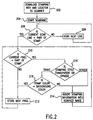
- Figure 2 is a flow chart of the stamping process in the scanning system. Once the scan has been initiated the stamping information and stamping location is downloaded from the host computer to the scanner and saved in the scanner memory 202.
- the scanner memory is typically one large memory that can be divided into smaller locations used for different tasks. One area can be used for storing downloaded information and one area can be used for buffering the scanning data to be sent to the host computer.
- the scanner then starts scanning the image to be scanned a scan line at a time 204.
- the current scan line is compared with the y-stamping location 206.
- the scanner scans the next line 208.
- the scanner compares the current pixel location to the x-stamp location 210.
- the stamping information is checked to see if the stamp style is transparent or opaque 216.
- the stamping style When the stamping style is opaque the stamping information replaces the digital image 214.
- the stamping style When the stamping style is transparent the stamping information for the current pixel is checked to see if the stamping color is equal to the background color.
- the stamping color does not equal the background color the stamping information replaces the digital image 214.
- the stamping color equals the background color the digital image is unaffected 212. This process continues until the stamp is completely inserted into the digital image.
- the scanned image is transferred to the host computer the scanned image contains the stamp information.
- the stamping information could be added to the scanned image inside the host computer instead of being downloaded into the scanner.
- the preferred embodiment is downloading the stamping information into the scanner.
- One of the advantages of having the scanner insert the stamping information is that the information is already in the scanned image as it leaves the scanner. This can be important if the image is being sent directly to a printer or some other peripheral device.
- the scanner can determine the high contrast color in two ways.
- the first way is to select the high contrast color based on the color of the total area where the text will be placed. This results in the text being one color.
- the second way is to pick a color for each pixel in the text, based on the color of the image where that pixel of text will be placed. This results in text that will have different colors throughout the text unless the image was a constant color where the text was placed.
- the average of the red, green, and blue image content of the area where the text will be place is calculated.
- the high contrast color would be calculated by comparing the average red, green, and blue colors to the midpoint of the allowable range for each color.
- each color has a range from 0 to 255.
- the midpoint of the range is 128.
- the red component for the text would be set at 0.
- the average of the red area is less than the midpoint of the red range the red component for the text would be set at 255. This is repeated for each color until all three color components for the text have been determined.
- the pixel replacement method uses the same process but it is repeated for each color component at each pixel.
- a digital camera is different than a scanner in that a digital camera is typically connected to the host computer only after a number of digital photographs have been created. This requires a digital camera to contain sufficient internal storage to hold a number of digital images.
- a digital camera typically does not contain a keyboard so it is more cumbersome for a user to enter textual information into a digital camera than into a computer.
- Digital cameras typically have bi-directional communication channels with host computers such that textual information can be downloaded from the host computer to the digital camera. Because of the cumbersome nature of inputting textual information into a digital camera, the preferred embodiment for the current invention is to have the user input the stamping information into the host computer and then downloading that information into the digital camera.
- the user would make the same choices for the stamping information, in the host, for the digital camera as they would for the scanner (see figure 1).
- the user would enable or disable the stamping function from the digital camera and select from a plurality of downloaded or predefined stamps contained in the digital camera.
- stamping is enabled the digital camera would stamp the information into the digital image in the same way as the scanner (see fig 2).
Landscapes
- Engineering & Computer Science (AREA)
- Multimedia (AREA)
- Signal Processing (AREA)
- Facsimiles In General (AREA)
- Editing Of Facsimile Originals (AREA)
Applications Claiming Priority (2)
| Application Number | Priority Date | Filing Date | Title |
|---|---|---|---|
| US361623 | 1999-07-27 | ||
| US09/361,623 US6512856B1 (en) | 1999-07-27 | 1999-07-27 | System and method for information stamping a digitized image |
Publications (3)
| Publication Number | Publication Date |
|---|---|
| EP1073256A2 true EP1073256A2 (fr) | 2001-01-31 |
| EP1073256A3 EP1073256A3 (fr) | 2002-02-06 |
| EP1073256B1 EP1073256B1 (fr) | 2003-10-08 |
Family
ID=23422795
Family Applications (1)
| Application Number | Title | Priority Date | Filing Date |
|---|---|---|---|
| EP00305967A Expired - Lifetime EP1073256B1 (fr) | 1999-07-27 | 2000-07-13 | Système et procédé de timbrage d'une image électronique avec information |
Country Status (3)
| Country | Link |
|---|---|
| US (1) | US6512856B1 (fr) |
| EP (1) | EP1073256B1 (fr) |
| DE (1) | DE60005761T2 (fr) |
Families Citing this family (12)
| Publication number | Priority date | Publication date | Assignee | Title |
|---|---|---|---|---|
| JP2001103269A (ja) * | 1999-09-28 | 2001-04-13 | Olympus Optical Co Ltd | プリンタ装置および電子カメラ装置 |
| US7346215B2 (en) * | 2001-12-31 | 2008-03-18 | Transpacific Ip, Ltd. | Apparatus and method for capturing a document |
| JP2004194129A (ja) * | 2002-12-13 | 2004-07-08 | Hitachi Ltd | 映像情報取引方法および映像情報を添付した工業製品 |
| US20050185225A1 (en) * | 2003-12-12 | 2005-08-25 | Brawn Dennis E. | Methods and apparatus for imaging documents |
| JP2005223758A (ja) * | 2004-02-06 | 2005-08-18 | Canon Inc | 画像処理装置及びその制御方法、コンピュータプログラム、記録媒体 |
| US7685516B2 (en) * | 2004-05-18 | 2010-03-23 | Ubs Ag | Creation of electronically processable signature files |
| US7172354B1 (en) | 2004-12-09 | 2007-02-06 | Y. Nissim, Inc. | Self-contained edge printer |
| KR101169994B1 (ko) * | 2005-04-07 | 2012-08-01 | 삼성전자주식회사 | 알파 평면을 이용한 영상 데이터 처리 장치 및 방법 |
| JP4217696B2 (ja) * | 2005-06-09 | 2009-02-04 | キヤノン株式会社 | 画像処理装置、画像処理方法及びプログラム |
| JP4852915B2 (ja) * | 2005-07-21 | 2012-01-11 | 富士ゼロックス株式会社 | タイムスタンプ取得プログラム、画像形成装置及びデジタルデータ管理システム |
| JP5703270B2 (ja) * | 2012-08-29 | 2015-04-15 | 京セラドキュメントソリューションズ株式会社 | 画像読取装置、文書管理システム、及び画像読取制御プログラム |
| KR20150068609A (ko) * | 2013-12-12 | 2015-06-22 | 삼성전자주식회사 | 이미지 정보 표시 방법 및 장치 |
Family Cites Families (13)
| Publication number | Priority date | Publication date | Assignee | Title |
|---|---|---|---|---|
| JPS6252553A (ja) | 1985-09-02 | 1987-03-07 | Matsushita Electric Ind Co Ltd | 印判加工方法及びその装置 |
| US4860039A (en) | 1985-10-31 | 1989-08-22 | Minolta Camera Kabushiki Kaisha | Photographic camera system and using thereof |
| US5389991A (en) | 1992-02-25 | 1995-02-14 | Fuji Photo Film Co., Ltd. | Camera having data recording device |
| JP3109690B2 (ja) | 1992-03-19 | 2000-11-20 | キヤノン株式会社 | 画像通信装置および画像通信方法 |
| NL9201570A (nl) * | 1992-09-10 | 1994-04-05 | Oce Nederland Bv | Werkwijze voor het bij toevoer van, door een eerste en een tweede signaalbron gegenereerde digitale beeldinformatiesignalen van een eerste soort en onder gebruikmaking van de in genoemde signalen aanwezige informatieinhoud betreffende de dichtheidswaarde, per beeldpunt genereren van beeldinformatiesignalen van een tweede soort ter verkrijging van beeldweergeefsignalen, alsmede een reproductiesysteem voor het uitvoeren van een dergelijke werkwijze. |
| JP3326971B2 (ja) | 1994-06-30 | 2002-09-24 | 富士ゼロックス株式会社 | 自動押印装置 |
| US6362829B1 (en) * | 1996-03-07 | 2002-03-26 | Agfa Corporation | Method for modifying a digital image |
| JPH09325400A (ja) | 1996-06-04 | 1997-12-16 | Olympus Optical Co Ltd | データ写し込み光学系 |
| US5901224A (en) * | 1996-10-21 | 1999-05-04 | Xerox Corporation | Quasi-reprographics with variable embedded data with applications to copyright management, and distribution control |
| US6222932B1 (en) * | 1997-06-27 | 2001-04-24 | International Business Machines Corporation | Automatic adjustment of image watermark strength based on computed image texture |
| US6275260B1 (en) * | 1997-09-17 | 2001-08-14 | Flashpoint Technology, Inc. | Positioning stamps in images captured with an image capture unit |
| WO1999014941A2 (fr) | 1997-09-17 | 1999-03-25 | Flashpoint Technology, Inc. | Procede et systeme de conversion des caracteristiques de marques |
| US6078873A (en) * | 1997-10-02 | 2000-06-20 | Cummins Engine Company, Inc. | Method and apparatus for real-time data stamping via datalink and volatile ECM timer/clock |
-
1999
- 1999-07-27 US US09/361,623 patent/US6512856B1/en not_active Expired - Fee Related
-
2000
- 2000-07-13 EP EP00305967A patent/EP1073256B1/fr not_active Expired - Lifetime
- 2000-07-13 DE DE60005761T patent/DE60005761T2/de not_active Expired - Lifetime
Also Published As
| Publication number | Publication date |
|---|---|
| US6512856B1 (en) | 2003-01-28 |
| EP1073256A3 (fr) | 2002-02-06 |
| DE60005761D1 (de) | 2003-11-13 |
| DE60005761T2 (de) | 2004-08-05 |
| EP1073256B1 (fr) | 2003-10-08 |
Similar Documents
| Publication | Publication Date | Title |
|---|---|---|
| US6980332B2 (en) | System and method of automated scan workflow assignment | |
| US20040247175A1 (en) | Image processing method, image capturing apparatus, image processing apparatus and image recording apparatus | |
| US7312824B2 (en) | Image-capturing apparatus, image processing apparatus and image recording apparatus | |
| US6636332B1 (en) | System for reproducing images and method thereof | |
| US20070139710A1 (en) | Image processing device having functions for detecting specified images | |
| US8982390B2 (en) | Image forming apparatus, image printing system, image combining and outputting method, and computer product | |
| JP2003533917A (ja) | ペーパーレススケーリングモードを伴うスキャナ | |
| US6512856B1 (en) | System and method for information stamping a digitized image | |
| KR100668267B1 (ko) | 화상 처리 장치, 화상 처리 방법 및 화상 처리 프로그램을 기록한 컴퓨터로 읽을 수 있는 매체 | |
| US8818110B2 (en) | Image processing apparatus that groups object images based on object attribute, and method for controlling the same | |
| US20040041926A1 (en) | Image-capturing apparatus, imager processing apparatus and image recording apparatus | |
| KR20080058779A (ko) | 화상형성장치 및 그 연사촬영 이미지의 제어방법 | |
| US7224383B2 (en) | Manipulating digital images based on a user profile | |
| US7561296B2 (en) | Image processing apparatus | |
| US7355766B2 (en) | Device for digital imaging and storage of a document | |
| US20030161608A1 (en) | Image reproducing apparatus and image reproducing method | |
| GB2402833A (en) | Facsimile file transmission control by user marks on sheet | |
| US20040212852A1 (en) | Method of scanning a document using a pre-scanning operation | |
| JP2004096508A (ja) | 画像処理方法、画像処理装置、画像記録装置、プログラム及び記録媒体 | |
| US20080043269A1 (en) | Method and apparatus for processing image containing picture and characters | |
| JPH10200919A (ja) | ダイレクトプリントアダプタ | |
| JP2003533918A (ja) | プリプレスモードを伴うスキャナ | |
| JP3302010B2 (ja) | 電子機器の制御方法 | |
| JP2004242232A (ja) | 記録媒体及び画像記録装置並びに画像記録方法 | |
| JP5413297B2 (ja) | 画像処理装置、画像処理方法、プログラムおよび記録媒体 |
Legal Events
| Date | Code | Title | Description |
|---|---|---|---|
| PUAI | Public reference made under article 153(3) epc to a published international application that has entered the european phase |
Free format text: ORIGINAL CODE: 0009012 |
|
| AK | Designated contracting states |
Kind code of ref document: A2 Designated state(s): AT BE CH CY DE DK ES FI FR GB GR IE IT LI LU MC NL PT SE Kind code of ref document: A2 Designated state(s): DE FR GB |
|
| AX | Request for extension of the european patent |
Free format text: AL;LT;LV;MK;RO;SI |
|
| RAP1 | Party data changed (applicant data changed or rights of an application transferred) |
Owner name: HEWLETT-PACKARD COMPANY, A DELAWARE CORPORATION |
|
| PUAL | Search report despatched |
Free format text: ORIGINAL CODE: 0009013 |
|
| AK | Designated contracting states |
Kind code of ref document: A3 Designated state(s): AT BE CH CY DE DK ES FI FR GB GR IE IT LI LU MC NL PT SE |
|
| AX | Request for extension of the european patent |
Free format text: AL;LT;LV;MK;RO;SI |
|
| 17P | Request for examination filed |
Effective date: 20020715 |
|
| AKX | Designation fees paid |
Free format text: DE FR GB |
|
| GRAH | Despatch of communication of intention to grant a patent |
Free format text: ORIGINAL CODE: EPIDOS IGRA |
|
| GRAS | Grant fee paid |
Free format text: ORIGINAL CODE: EPIDOSNIGR3 |
|
| GRAA | (expected) grant |
Free format text: ORIGINAL CODE: 0009210 |
|
| AK | Designated contracting states |
Kind code of ref document: B1 Designated state(s): DE FR GB |
|
| REG | Reference to a national code |
Ref country code: GB Ref legal event code: FG4D |
|
| REG | Reference to a national code |
Ref country code: IE Ref legal event code: FG4D |
|
| REF | Corresponds to: |
Ref document number: 60005761 Country of ref document: DE Date of ref document: 20031113 Kind code of ref document: P |
|
| ET | Fr: translation filed | ||
| PLBE | No opposition filed within time limit |
Free format text: ORIGINAL CODE: 0009261 |
|
| STAA | Information on the status of an ep patent application or granted ep patent |
Free format text: STATUS: NO OPPOSITION FILED WITHIN TIME LIMIT |
|
| 26N | No opposition filed |
Effective date: 20040709 |
|
| REG | Reference to a national code |
Ref country code: IE Ref legal event code: MM4A |
|
| REG | Reference to a national code |
Ref country code: GB Ref legal event code: 732E Free format text: REGISTERED BETWEEN 20120329 AND 20120404 |
|
| PGFP | Annual fee paid to national office [announced via postgrant information from national office to epo] |
Ref country code: GB Payment date: 20130626 Year of fee payment: 14 |
|
| PGFP | Annual fee paid to national office [announced via postgrant information from national office to epo] |
Ref country code: DE Payment date: 20130621 Year of fee payment: 14 |
|
| PGFP | Annual fee paid to national office [announced via postgrant information from national office to epo] |
Ref country code: FR Payment date: 20130722 Year of fee payment: 14 |
|
| REG | Reference to a national code |
Ref country code: DE Ref legal event code: R119 Ref document number: 60005761 Country of ref document: DE |
|
| GBPC | Gb: european patent ceased through non-payment of renewal fee |
Effective date: 20140713 |
|
| REG | Reference to a national code |
Ref country code: FR Ref legal event code: ST Effective date: 20150331 |
|
| PG25 | Lapsed in a contracting state [announced via postgrant information from national office to epo] |
Ref country code: DE Free format text: LAPSE BECAUSE OF NON-PAYMENT OF DUE FEES Effective date: 20150203 |
|
| REG | Reference to a national code |
Ref country code: DE Ref legal event code: R119 Ref document number: 60005761 Country of ref document: DE Effective date: 20150203 |
|
| PG25 | Lapsed in a contracting state [announced via postgrant information from national office to epo] |
Ref country code: GB Free format text: LAPSE BECAUSE OF NON-PAYMENT OF DUE FEES Effective date: 20140713 Ref country code: FR Free format text: LAPSE BECAUSE OF NON-PAYMENT OF DUE FEES Effective date: 20140731 |