EP1073363B1 - Dispositif medical permettant d'acceder a l'interieur du corps - Google Patents
Dispositif medical permettant d'acceder a l'interieur du corps Download PDFInfo
- Publication number
- EP1073363B1 EP1073363B1 EP99918652A EP99918652A EP1073363B1 EP 1073363 B1 EP1073363 B1 EP 1073363B1 EP 99918652 A EP99918652 A EP 99918652A EP 99918652 A EP99918652 A EP 99918652A EP 1073363 B1 EP1073363 B1 EP 1073363B1
- Authority
- EP
- European Patent Office
- Prior art keywords
- head
- medical device
- handle
- head half
- handle portion
- Prior art date
- Legal status (The legal status is an assumption and is not a legal conclusion. Google has not performed a legal analysis and makes no representation as to the accuracy of the status listed.)
- Expired - Lifetime
Links
Images




Classifications
-
- A—HUMAN NECESSITIES
- A61—MEDICAL OR VETERINARY SCIENCE; HYGIENE
- A61B—DIAGNOSIS; SURGERY; IDENTIFICATION
- A61B1/00—Instruments for performing medical examinations of the interior of cavities or tubes of the body by visual or photographical inspection, e.g. endoscopes; Illuminating arrangements therefor
- A61B1/32—Devices for opening or enlarging the visual field, e.g. of a tube of the body
-
- A—HUMAN NECESSITIES
- A61—MEDICAL OR VETERINARY SCIENCE; HYGIENE
- A61B—DIAGNOSIS; SURGERY; IDENTIFICATION
- A61B1/00—Instruments for performing medical examinations of the interior of cavities or tubes of the body by visual or photographical inspection, e.g. endoscopes; Illuminating arrangements therefor
- A61B1/06—Instruments for performing medical examinations of the interior of cavities or tubes of the body by visual or photographical inspection, e.g. endoscopes; Illuminating arrangements therefor with illuminating arrangements
- A61B1/0661—Endoscope light sources
- A61B1/0669—Endoscope light sources at proximal end of an endoscope
-
- A—HUMAN NECESSITIES
- A61—MEDICAL OR VETERINARY SCIENCE; HYGIENE
- A61B—DIAGNOSIS; SURGERY; IDENTIFICATION
- A61B1/00—Instruments for performing medical examinations of the interior of cavities or tubes of the body by visual or photographical inspection, e.g. endoscopes; Illuminating arrangements therefor
- A61B1/06—Instruments for performing medical examinations of the interior of cavities or tubes of the body by visual or photographical inspection, e.g. endoscopes; Illuminating arrangements therefor with illuminating arrangements
- A61B1/07—Instruments for performing medical examinations of the interior of cavities or tubes of the body by visual or photographical inspection, e.g. endoscopes; Illuminating arrangements therefor with illuminating arrangements using light-conductive means, e.g. optical fibres
Definitions
- This invention relates to a medical device that allows access to the inside of the body by "prying open” an existing or created opening in a body.
- a retractor typically is used to draw aside the edges of a wound or opening (e.g., to separate and hold open the rib cage of a patient) or to hold back structures adjacent an operative field.
- a speculum typically is used to enlarge the opening of any canal or cavity (e.g., the vagina or the rectum) to facilitate inspection of the interior of the canal or cavity.
- levers or handles of retractors and specula are disposed in the line of sight of the body cavity in which the device is inserted thus interfering with an operator's (e.g., a physician's) ability to examine and view the cavity and to properly place medical instruments into the cavity.
- Retractors and specula also typically limit or prevent tactile access. That is, an operator typically cannot insert a hand or a finger into the body opening being held or forced open by the device.
- Retractors and specula are typically made of steel, causing discomfort to the patient. Improper sterilization and repeated use of these instruments also increases the risk of infection.
- Document CH-A-0273 809 purports to disclose a device for retraction including substantially transparent plastic masses 47 and 48 with light sources directing illumination therethrough.
- This invention relates to a medical retractor/speculum device for vaginal or other applications that allows access to the inside of the body by "prying open” an existing or created opening in a body.
- the device has scissors-like handles to allow an operator to open or close the device with one hand.
- the device has a locking mechanism to allow the device to stay closed, open, or partially open, as placed by the operator with one hand.
- a medical device for retracting a body opening comprises a substantially transparent head coupled to a handle.
- the head comprises a first head half and a second head half which together define a substantially conical surface including a gap when the first head half and second head half are joined.
- the handle is coupled to the wider base of the head and comprises two handle portions that can be joined at a common hinge or pivot point.
- the handle portions can be manipulated like the handles of a pair of scissors. Actuation of the handle by bringing the handle portions together causes angular motion of the first head half and the second head half relative to a longitudinal axis of the head, exerting a retraction force on the body opening, thereby enlarging the body opening. Actuation also enlarges the gap in the head so as to provide the operator with an area of access to the inside of the body opening through the gap.
- the increase in the size of the gap upon actuation of the handle allows the operator to insert at least a finger, and preferably most of the hand up to the knuckles, into the segment of the head which extends outside of the body opening. This allows the operator the ability to touch the inside of the body opening being retracted and to identify structure(s) within the body opening. As the handle portions can be manipulated with a single hand, the other hand of the operator is free to examine the patient.
- a longitudinal axis of the handle is substantially perpendicular to the longitudinal axis of the head, and the handle is disposed out of the line of sight of the body cavity.
- the retractor/speculum device can be configured to include a light source or to receive one or more light-transmitting fibers or cables. The light will illuminate at least the substantially transparent head of the device to provide illumination of the retracted area.
- the device of the invention allows transvaginal surgical procedures to proceed more quickly and safely than when other known devices are used. One-hand operation of the device is possible, in accordance with the invention.
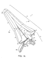
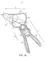
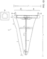
- Figures 1A-D show perspective views of a retractor/speculum device in a closed position according to one embodiment of the invention.
- Figure 1A is perspective view from the top of the device showing the gap formed between the two halves of the head of the device.
- Figure 1B is a perspective view from the side and back of the device showing the gap formed between the two halves of the head.
- Figure 1C is perspective view of the back of the device.
- Figure 1D is a view of the bottom of the head of the retractor/speculum of Figure 1.
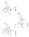
- Figures 2A and 2B show perspective views of a retractor/speculum device in an open position according to one embodiment of the invention.
- Figure 2A is a perspective view from the side and back of the device showing the enlarged gap formed between the two halves of the head of the device.
- Figure 2B is a perspective view of the back of the device.
- Figure 3A is a back view of one half of the retractor/speculum of Figure 1.
- Figure 3B is a perspective view of the half shown in Figure 3A.
- Figure 4A shows the back of a retractor/speculum device according to one embodiment of the invention which includes a locking mechanism.
- Figure 4B shows an enlarged view of the locking mechanism of the device.
- Figure 5A shows a perspective view of an embodiment of the invention in which a locking mechanism is provided as part of the hinge assembly of the retractor/speculum device.
- Figure 5B shows a side view of this embodiment.
- Figures 6A-C show enlarged views of hinge assembles according to different embodiments of the invention.
- Figure 7 shows a schematic diagram of the movement of each head half of the retractor/speculum device upon actuation of the handle.
- the left side of the figure shows the device in a closed configuration.
- the right side of the figure shows the device in an open configuration.
- a device according to the invention is useful for retraction and functions as a medical retractor and/or speculum.
- the device 1 comprises a head 2 and a handle 3.
- both the head 2 and handle 3 comprise two substantially symmetrical halves (first head half 2a and second head half 2b , and handle portions 3a and 3b , respectively) which are generally mirror images of each other.
- the two halves 2a and 2b of the head 2 are capable of angular motion relative to a longitudinal axis 23 of the head 2 upon actuation or manipulation of the handle 3 , moving away from each other through an arcuate path when the device is being “opened” to exert a retraction force, and moving toward each other when the device is being “closed.”
- the device 1 can be made of a substantially transparent thermoplastic material that transmits light, such as polycarbonate (e.g., Lexan OQ®, Flexlite Corporation, Boca Raton, FL), acrylic, or polystyrene, although any type of material that can resist the retraction force of the area being retracted and that can transmit light when illuminated can be used.
- the device 1 may be entirely substantially transparent or the head 2 alone may be substantially transparent.
- a substantially transparent material is intended to include any material that can transmit light.
- plastic has several advantages as a material for the retractor/speculum device 1 (or the head 2 alone) of the invention.
- a plastic device 1 is disposable and provides a single-use medical instrument that helps to eliminate the occurrence of cross-infection typically associated with improperly sterilized multi-use metal instruments.
- plastic has a lower coefficient of thermal conductivity than steel or metal, the patient experiences less discomfort as the retractor/speculum device 1 of the invention feels warmer and more comfortable to the patient.
- a substantially transparent material, such as clear plastic results in a device 1 that acts as a light pipe.
- a light source or fiber optic lines carrying light from a light source, can be coupled directly to the device 1 , to illuminate the substantially transparent portions of the device 1 and thus allow the operator to see the body cavity or tract opened by the device 1 .
- the first and second head halves 2a and 2b define a substantially conical surface with an open base 20.
- the outer surface o of the first and second head halves 2a and 2b is generally convex and the inner surface i of the first and second head halves 2a and 2b is generally concave.
- substantially conical includes any surface which circumscribes a lumen with a continuously varying internal diameter.
- each half of the head 2 may be divided into four basic elements which contribute to the head 2 's substantially conical surface: half of a semicircular ridge 5 which is the point of coupling for one of the handle portions ( 3a or 3b ) of the handle 3 and which forms the base of the conical surface; half of a first frustoconical portion 6 which is proximal to the semicircular ridge 5 ; half of a second frustoconical portion 7 adjacent to the first frustoconical portion 6 ; and half of a tip portion 8 , located at the distal insertion end of the head portion 2 .
- the first frustoconical portion 6 is generally wider in radius than the second frustoconical portion 7 .
- a head half and respective handle portion may be molded as a single piece, being integral with a respective handle portion; alternatively, a head half may be attached or fused to a handle piece which is molded separately.
- a discrete semicircular ridge 5 may not be present and the handle portions 3a and 3b may be attached directly to the respective halves of frustoconical portion 6 .
- the first and second head halves 2a and 2b are in close proximity.
- the first head half 2a and the second head half 2b contact each other along a midline 9 along the lower surface of the head 2.
- the upper surface of both the first frustoconical portion 6 and the second frustoconical portion 7 are partially "cut-away" such that when the two halves of the head are in close proximity, the upper surface of the head 2 comprises a gap 4.
- the handle portions 3a and 3b of the handle 3 causes the first and second head halves 2a and 2b to splay apart (e.g., as shown in Figures 2A and 2B and in the right-hand side of Figure 7), thereby enlarging the body opening.
- the gap 4 in the head 2 enlarges.
- This enlarged gap 4 together with opening 20 at the base of the head 2 , provides an area of access that allows the operator to insert one or more fingers into the body cavity and inspect the body cavity tactily at least near the gap 4 .
- the gap 4 also provides the operator with the ability to insert a variety of medical instruments into the body cavity, for example a suturing mechanism.
- the device 1 may be opened completely or may be opened to an intermediary position, depending upon the amount of clearance required.
- the handle 3 of the device 1 comprises two halves, namely, handle portion 3a and 3b.
- the two handle portions 3a and 3b join at a hinge assembly 10.
- hinge assembly 10 comprises hinge elements 10a and 10b , which are extensions of handle portions 3a and 3b, respectively, and comprise complementary shapes.
- Hinge elements 10a and 10b are connected at a pivot point 11.
- the hinge elements 10a and 10b may have coupling elements, such as mating plastic elements 12a and 12b , respectively, that snap together to form the pivot point 11 ( Figure 6A).
- the hinge elements 10a and 10b can be joined by a bolt or rod 13 inserted at a hole 14 that runs through each hinge element 10a and 10b ( Figure 6B).
- the bolt or rod 13 may be secured by a nut or pin.
- the two handle portions 3a and 3b join at a different type of hinge assembly 15 .
- one of the handle portions, in this example, 3b comprises a first and second interconnection element 15u and 15l
- the other handle portion, in this example, 3a comprises an inner interconnection element 15m .
- the inner interconnection element 15m is sandwiched, or interleaved, between the first and second outer interconnection elements 15u and 15l by a coupling element at pivot point 11.
- interconnection elements 15u, 15l, and 15m may be joined together by means of plastic mating elements 12a and 12b (as shown in Figure 6C) or by a bolt or rod.
- the handle 3 further comprises a locking mechanism 16 .
- the locking mechanism comprises two sets 16a and 16b of resilient, evenly spaced lugs, each set projecting from the distal ends of first and second cross-bars 17a and 17b, which extend from handle portions 3a and 3b, respectively, in a direction generally perpendicular to the longitudinal axis of the handle 3.
- Cross-bars 17a and 17b are slightly offset from each other and the lugs at the distal end of one cross-bar point in an opposite direction to the lugs at the distal end of the other cross-bar such that both sets of lugs 16a and 16b can snap together to effectively lock the device.
- the locking mechanism 16 may be released by the operator applying a twisting action with one hand to the handle portions 3a and 3b thereby unsnapping the lugs.
- the operator may release the locking mechanism 16 by pushing down on a thumb tab 18 at the distal end of one of the cross-bars.
- an integrated locking mechanism/hinge assembly 21 is provided.
- one of the handle portions, in this example, 3b, may comprise a mating hinge element 21m which comprises a plurality of projections 21p .
- the other handle portion, in this example, 3a comprises an engaging portion 21e , which is capable of meshing with one of the projections 21p of the mating hinge element 21m to lock the device in a selected position.
- the mating hinge element 21m may be configured to comprise any number and arrangement of projections 21p, so long as the position of the projections 21p relative to the engaging portion 21e changes upon movement of the handle portions, 3a and 3b, to restrict further movement of the handle 3
- manipulation of the handle portions 3a and 3b with the single hand of an operator can engage this locking mechanism.
- the orientation of the handle 3 relative to the head 2 of the device 1 may be varied to provide an operator with freer access to a body opening.
- the handle portions 3a and 3b of the handle 3 are disposed substantially perpendicular to the two halves 2a and 2b , respectively, of the head 2 .
- This arrangement allows the operator to have access to the head 2 and the body cavity in which the head 2 is inserted without interference from the two handle portions 3a and 3b .
- substantially perpendicular refers to an orientation of the handle 3 relative to the head 2 in which the handle 3 is out of the line of sight of the body opening.
- the two handle portions 3a and 3b of the handle 3 can also be oriented at other than 90 degrees from the two halves 2a and 2b of the head 2 .
- the two handle portions 3a and 3b of the handle 3 can be oriented in the same plane as the longitudinal axis 23 of the head 2 to a point on the handle 3 distal to a hinge assembly 10 or 15.
- the two handle portions 3a and 3b of the handle 3 could then angle downward in a direction away from the opening 20 at the base of the head 2 .
- the two handle portions 3a and 3b of the handle 3 have a 30 degree angle of activation.
- a fixture or socket 19 for receiving one or more light-transmitting fiber optic lines or cables or a light source can be disposed on the semicircular ridge 5 (or on the rim of frustoconical portion 6 when there is no ridge) of one or both halves 2a and 2b of the head 2.
- the socket(s) 19 can be cylindrical-shaped with a ribbon element 22 that retains the cable(s) or the light source, preferably by a collapsible friction fit.
- the shape and size of the socket(s) 19 can be complementary to any fiber optic light cable(s) or light source that is known in the art.
- the socket(s) 19 can be located elsewhere, such as on handle portion 3a and/or 3b.
- the cable(s) or light source provides a means to illuminate the device 1 and allow the operator to see into the body cavity being retracted without the need for an external light being shined into the body cavity by an individual assisting the operator.
- the longitudinal axis of the handle 3 extends substantially perpendicularly from the head 2 of the device 1 , only the head 2 of the device 1 need be substantially transparent.
- the dimensions of the device 1 can be as follows: L1 can be approximately 20 cm (8 inches) and L2 can be approximately 5 cm (2 inches). In the embodiment of the invention shown in FIG. 1D, the dimensions of the device 1 can be as follows: L3 can be approximately 2.5 cm (1 inch), L4 can be approximately 4 cm (1 5/8 inches), L5 can be approximately 7.5 cm (3 inches), and L6 can be approximately 12.5 cm (5 inches).
Landscapes
- Health & Medical Sciences (AREA)
- Life Sciences & Earth Sciences (AREA)
- Surgery (AREA)
- Biomedical Technology (AREA)
- Medical Informatics (AREA)
- Optics & Photonics (AREA)
- Pathology (AREA)
- Radiology & Medical Imaging (AREA)
- Biophysics (AREA)
- Engineering & Computer Science (AREA)
- Physics & Mathematics (AREA)
- Heart & Thoracic Surgery (AREA)
- Nuclear Medicine, Radiotherapy & Molecular Imaging (AREA)
- Molecular Biology (AREA)
- Animal Behavior & Ethology (AREA)
- General Health & Medical Sciences (AREA)
- Public Health (AREA)
- Veterinary Medicine (AREA)
- Endoscopes (AREA)
- Surgical Instruments (AREA)
Abstract
Claims (16)
- Dispositif médical à des fins de rétraction, comprenant :une tête essentiellement transparente (2) comprenant une première moitié de tête (20), une deuxième moitié de tête (26), et un axe longitudinal, la première moitié de tête et la deuxième moitié de tête définissant une surface essentiellement conique englobant un espace libre (4), lorsque la première moitié de tête et la deuxième moitié de tête sont jointes ; etune poignée (3) couplée à la tête, l'actionnement de la poignée provoquant le mouvement angulaire de la première moitié de tête et de la deuxième moitié de tête par rapport à l'axe longitudinal, de façon à élargir l'espace libre.
- Dispositif médical selon la revendication 1, dans lequel la première moitié de tête et la deuxième moitié de tête comprennent une matière thermoplastique.
- Dispositif médical selon la revendication 2, dans lequel ladite matière thermoplastique comprend du polycarbonate.
- Dispositif médical selon la revendication 1, dans lequel la poignée comprend une première portion de poignée (3a) et une deuxième portion de poignée (3b), la première portion de poignée étant couplée à la première moitié de tête et la deuxième portion de poignée étant couplée à la deuxième moitié de tête, les première et deuxième portions de poignée étant jointes à un point de pivotement commun.
- Dispositif médical selon la revendication 4, dans lequel la première portion de poignée est solidaire de la première moitié de tête et la deuxième portion de poignée est solidaire de la deuxième moitié de tête.
- Dispositif médical selon la revendication 4, dans lequel la première portion de poignée comprend des premier et deuxième éléments d'interconnexion externes, et la deuxième portion de poignée comprend un élément d'interconnexion interne, l'élément d'interconnexion interne étant intercalé entre les premier et deuxième éléments d'interconnexion externes et étant connecté à ces derniers par un élément de couplage au point de pivotement.
- Dispositif médical selon la revendication 6, dans lequel l'élément de couplage comprend un boulon.
- Dispositif médical selon la revendication 7, dans lequel l'élément de couplage comprend deux éléments plastiques conjugués qui viennent s'encliqueter l'un dans l'autre.
- Dispositif médical selon la revendication 4, dans lequel au moins une des première et deuxième portions de poignée englobe une douille (19).
- Dispositif médical selon la revendication 9, dans lequel la douille englobe une source de lumière.
- Dispositif médical selon la revendication 9, dans lequel un ou plusieurs câbles de transmission de lumière viennent se loger dans la douille.
- Dispositif médical selon la revendication 1, dans lequel la poignée englobe un mécanisme de verrouillage.
- Dispositif médical selon la revendication 1, comprenant en outre une source de lumière pour éclairer au moins la tête.
- Dispositif médical selon la revendication 13, comprenant en outre une ou plusieurs douilles.
- Dispositif médical selon la revendication 14, dans lequel au moins une des douilles englobe ladite source de lumière.
- Dispositif médical selon la revendication 14, dans lequel une ou plusieurs fibres de transmission de lumière viennent se loger dans au moins une des douilles.
Applications Claiming Priority (3)
| Application Number | Priority Date | Filing Date | Title |
|---|---|---|---|
| US8271898P | 1998-04-23 | 1998-04-23 | |
| US82718P | 1998-04-23 | ||
| PCT/US1999/008494 WO1999053829A1 (fr) | 1998-04-23 | 1999-04-22 | Dispositif medical permettant d'acceder a l'interieur du corps |
Publications (2)
| Publication Number | Publication Date |
|---|---|
| EP1073363A1 EP1073363A1 (fr) | 2001-02-07 |
| EP1073363B1 true EP1073363B1 (fr) | 2004-10-06 |
Family
ID=22172991
Family Applications (1)
| Application Number | Title | Priority Date | Filing Date |
|---|---|---|---|
| EP99918652A Expired - Lifetime EP1073363B1 (fr) | 1998-04-23 | 1999-04-22 | Dispositif medical permettant d'acceder a l'interieur du corps |
Country Status (7)
| Country | Link |
|---|---|
| US (2) | US6450952B1 (fr) |
| EP (1) | EP1073363B1 (fr) |
| JP (1) | JP4384355B2 (fr) |
| AU (1) | AU740502B2 (fr) |
| CA (1) | CA2328993C (fr) |
| DE (1) | DE69920896T2 (fr) |
| WO (1) | WO1999053829A1 (fr) |
Families Citing this family (122)
| Publication number | Priority date | Publication date | Assignee | Title |
|---|---|---|---|---|
| US6663563B1 (en) * | 1998-10-02 | 2003-12-16 | Minnesota Scientific, Inc. | Fastening system for retractor support |
| AU1998600A (en) | 1999-01-08 | 2000-07-24 | American Medical Systems International, Inc. | Tack device |
| CA2363254C (fr) | 1999-03-07 | 2009-05-05 | Discure Ltd. | Procede et appareil de chirurgie informatisee |
| US7470236B1 (en) | 1999-11-24 | 2008-12-30 | Nuvasive, Inc. | Electromyography system |
| US6569091B2 (en) * | 2000-05-04 | 2003-05-27 | Ananias Diokno | Disconnectable vaginal speculum with removeable blades |
| US6302842B1 (en) * | 2001-01-11 | 2001-10-16 | Innovative Surgical Design Llc | Episiotomy retractor |
| US6986772B2 (en) | 2001-03-01 | 2006-01-17 | Michelson Gary K | Dynamic lordotic guard with movable extensions for creating an implantation space posteriorly in the lumbar spine |
| WO2002069891A2 (fr) | 2001-03-01 | 2002-09-12 | Michelson Gary K | Protection lordotique dynamique a rallonges mobiles permettant de creer un espace d'implantation vers l'arriere de la colonne lombaire et son procede d'utilisation |
| US6896680B2 (en) | 2001-03-01 | 2005-05-24 | Gary K. Michelson | Arcuate dynamic lordotic guard with movable extensions for creating an implantation space posteriorly in the lumbar spine |
| WO2003005887A2 (fr) | 2001-07-11 | 2003-01-23 | Nuvasive, Inc. | Systeme et methodes permettant de determiner la proximite d'un nerf et sa position par rapport a un instrument chirurgical, ainsi que son etat, lors d'une operation chirurgicale |
| JP2005503857A (ja) | 2001-09-25 | 2005-02-10 | ヌバシブ, インコーポレイテッド | 外科処置手順および外科的診断を実施するためのシステムおよび方法 |
| US20050215858A1 (en) * | 2002-03-07 | 2005-09-29 | Vail William B Iii | Tubular personal pelvic viewers |
| US7261688B2 (en) * | 2002-04-05 | 2007-08-28 | Warsaw Orthopedic, Inc. | Devices and methods for percutaneous tissue retraction and surgery |
| US8147421B2 (en) | 2003-01-15 | 2012-04-03 | Nuvasive, Inc. | System and methods for determining nerve direction to a surgical instrument |
| US6945933B2 (en) * | 2002-06-26 | 2005-09-20 | Sdgi Holdings, Inc. | Instruments and methods for minimally invasive tissue retraction and surgery |
| US7582058B1 (en) | 2002-06-26 | 2009-09-01 | Nuvasive, Inc. | Surgical access system and related methods |
| US7473222B2 (en) * | 2002-06-26 | 2009-01-06 | Warsaw Orthopedic, Inc. | Instruments and methods for minimally invasive tissue retraction and surgery |
| US8137284B2 (en) | 2002-10-08 | 2012-03-20 | Nuvasive, Inc. | Surgical access system and related methods |
| JP4465179B2 (ja) * | 2002-11-20 | 2010-05-19 | メドサージ・メディカル・プロダクツ・コーポレイション | 肛門鏡 |
| JP2010131414A (ja) * | 2002-11-20 | 2010-06-17 | Medsurge Medical Products Corp | 肛門鏡 |
| US6869398B2 (en) * | 2003-01-06 | 2005-03-22 | Theodore G. Obenchain | Four-blade surgical speculum |
| US7691057B2 (en) | 2003-01-16 | 2010-04-06 | Nuvasive, Inc. | Surgical access system and related methods |
| US7819801B2 (en) | 2003-02-27 | 2010-10-26 | Nuvasive, Inc. | Surgical access system and related methods |
| US7481766B2 (en) * | 2003-08-14 | 2009-01-27 | Synthes (U.S.A.) | Multiple-blade retractor |
| US7182729B2 (en) * | 2003-09-18 | 2007-02-27 | Stryker Spine | Surgical retractor with removable scissor arms |
| WO2005030318A1 (fr) | 2003-09-25 | 2005-04-07 | Nuvasive, Inc. | Systeme d'acces chirurgical et procedes correspondant |
| US7905840B2 (en) | 2003-10-17 | 2011-03-15 | Nuvasive, Inc. | Surgical access system and related methods |
| US8313430B1 (en) | 2006-01-11 | 2012-11-20 | Nuvasive, Inc. | Surgical access system and related methods |
| AU2004303424C1 (en) | 2003-12-18 | 2009-11-05 | Depuy Spine, Inc. | Surgical retractor systems, illuminated cannulae, and methods of use |
| US7798960B2 (en) * | 2004-02-09 | 2010-09-21 | John C. Jaeger | Speculum |
| US20070043264A1 (en) * | 2004-05-25 | 2007-02-22 | Innovative Gynecological Solutions, Llc | Speculum |
| US9622732B2 (en) | 2004-10-08 | 2017-04-18 | Nuvasive, Inc. | Surgical access system and related methods |
| WO2006047652A2 (fr) * | 2004-10-26 | 2006-05-04 | Concept Matrix, Llc | Voie de travail pour chirurgie vertebrale a incision minimale |
| US7575579B2 (en) * | 2004-11-18 | 2009-08-18 | Union Surgical, Llc | Drill guide tissue protector |
| EP1833379B1 (fr) * | 2005-01-07 | 2016-08-24 | Stryker European Holdings I, LLC | Ecarteur a trois branches presentant une gaine elastomere |
| US20060178698A1 (en) * | 2005-02-08 | 2006-08-10 | Mcintyre Jon T | Method and device for canulation and occlusion of uterine arteries |
| US8388523B2 (en) | 2005-04-01 | 2013-03-05 | Welch Allyn, Inc. | Medical diagnostic instrument having portable illuminator |
| WO2006107878A2 (fr) | 2005-04-01 | 2006-10-12 | Welch Allyn, Inc. | Ensemble d'eclairage conçu pour etre utilise avec un speculum vaginal |
| US7384393B2 (en) * | 2005-04-04 | 2008-06-10 | Guinan William P | Vaginal speculum |
| WO2006122031A2 (fr) | 2005-05-06 | 2006-11-16 | Welch Allyn, Inc. | Mecanisme articule pour speculum vaginal |
| EP1736095A1 (fr) * | 2005-06-22 | 2006-12-27 | Royal College Of Art | Speculum |
| US8328851B2 (en) | 2005-07-28 | 2012-12-11 | Nuvasive, Inc. | Total disc replacement system and related methods |
| EP1752106A1 (fr) * | 2005-08-11 | 2007-02-14 | Cardio Life Research S.A. | Ecarteur chirurgical. |
| EP1940282B1 (fr) | 2005-10-26 | 2009-06-10 | REBUFFAT, Carlo | Anoscope pour diagnostic ano-rectal et chirurgie |
| US7981031B2 (en) | 2006-01-04 | 2011-07-19 | Depuy Spine, Inc. | Surgical access devices and methods of minimally invasive surgery |
| US7758501B2 (en) | 2006-01-04 | 2010-07-20 | Depuy Spine, Inc. | Surgical reactors and methods of minimally invasive surgery |
| US7955257B2 (en) | 2006-01-05 | 2011-06-07 | Depuy Spine, Inc. | Non-rigid surgical retractor |
| US8142352B2 (en) | 2006-04-03 | 2012-03-27 | Welch Allyn, Inc. | Vaginal speculum assembly having portable illuminator |
| US7758203B2 (en) | 2006-04-03 | 2010-07-20 | Welch Allyn, Inc. | Power connections and interface for compact illuminator assembly |
| EP2015668A4 (fr) * | 2006-04-24 | 2010-01-20 | Ass For Public Health Services | Spéculum jetable |
| US20070255110A1 (en) * | 2006-04-28 | 2007-11-01 | Maine Medical Center | Operative vaginal speculum |
| JP2007319516A (ja) * | 2006-06-02 | 2007-12-13 | Norikata Taguma | 形状記憶合金を用いた胃瘻用チューブとその使用法 |
| US20080033251A1 (en) * | 2006-06-30 | 2008-02-07 | Ali Araghi | Surgical retractor and method of use |
| US8211013B2 (en) * | 2006-09-26 | 2012-07-03 | Trinty Orthopedics, LLC. | Speculum |
| US8062217B2 (en) * | 2007-01-26 | 2011-11-22 | Theken Spine, Llc | Surgical retractor with removable blades and method of use |
| US20080183044A1 (en) * | 2007-01-26 | 2008-07-31 | Dennis Colleran | Flexible surgical retractor and method of use |
| ATE499048T1 (de) * | 2007-03-07 | 2011-03-15 | Covidien Ag | Klammergerät für mukosektomie |
| WO2009082656A1 (fr) * | 2007-12-21 | 2009-07-02 | Smith & Nephew, Inc. | Cathéter |
| US8118739B2 (en) * | 2008-01-23 | 2012-02-21 | Mizuho America | Endonasal speculum |
| US8968192B2 (en) * | 2008-06-06 | 2015-03-03 | Warsaw Orthopedic, Inc. | Systems and methods for tissue retraction |
| US8096945B2 (en) * | 2008-06-13 | 2012-01-17 | Obp Corporation | Disposable speculums having single-sided support and operating mechanism |
| US8181838B2 (en) | 2008-09-10 | 2012-05-22 | Tyco Healthcare Group Lp | Surgical stapling device |
| US8226554B2 (en) | 2008-10-30 | 2012-07-24 | Warsaw Orthopedic, Inc. | Retractor assemblies for surgery in a patient |
| US8348837B2 (en) | 2008-12-09 | 2013-01-08 | Covidien Lp | Anoscope |
| CA2750917A1 (fr) | 2008-12-26 | 2010-07-01 | Scott Spann | Approche laterale retroperitoneale a invasion minime pour chirurgie spinale |
| US8287597B1 (en) | 2009-04-16 | 2012-10-16 | Nuvasive, Inc. | Method and apparatus for performing spine surgery |
| US9351845B1 (en) | 2009-04-16 | 2016-05-31 | Nuvasive, Inc. | Method and apparatus for performing spine surgery |
| US9204789B2 (en) | 2009-10-08 | 2015-12-08 | Covidien Lp | Asymmetrical anoscope |
| US9307897B2 (en) | 2010-09-28 | 2016-04-12 | Obp Corporation | Disposable speculum having lateral stabilizing mechanism |
| US9913577B2 (en) | 2010-09-28 | 2018-03-13 | Obp Medical Corporation | Speculum |
| WO2012050961A1 (fr) * | 2010-09-29 | 2012-04-19 | Ams Research Corporation | Systèmes, outils et procédés pour le traitement d'affections pelviennes |
| RU2567270C2 (ru) * | 2010-09-29 | 2015-11-10 | Альфред Е. Манн Инститьют Фор Байомедикал Инджиниринг Эт Дзе Юниверсити Оф Саутерн Калифорния | Ретрактор, создающий минимум помех |
| US9131935B2 (en) | 2010-10-01 | 2015-09-15 | K2M, Inc. | Retractor |
| US9155503B2 (en) | 2010-10-27 | 2015-10-13 | Cadwell Labs | Apparatus, system, and method for mapping the location of a nerve |
| US8790406B1 (en) | 2011-04-01 | 2014-07-29 | William D. Smith | Systems and methods for performing spine surgery |
| US8636656B2 (en) | 2011-08-16 | 2014-01-28 | Warsaw Orthopedic, Inc. | Retractor assemblies with blade drive mechanisms |
| WO2013028571A1 (fr) | 2011-08-19 | 2013-02-28 | Lanx, Inc. | Système d'écarteur chirurgical et procédés d'utilisation |
| US9592041B2 (en) * | 2011-10-18 | 2017-03-14 | Warsaw Orthopedic, Inc. | Surgical retractor assembly and method |
| US9198765B1 (en) | 2011-10-31 | 2015-12-01 | Nuvasive, Inc. | Expandable spinal fusion implants and related methods |
| US9295401B2 (en) | 2012-11-27 | 2016-03-29 | Cadwell Laboratories, Inc. | Neuromonitoring systems and methods |
| US9072501B2 (en) | 2013-03-15 | 2015-07-07 | Regents Of The University Of Minnesota | Micro-orifice surgical access system |
| US10098585B2 (en) | 2013-03-15 | 2018-10-16 | Cadwell Laboratories, Inc. | Neuromonitoring systems and methods |
| CN105578971A (zh) * | 2013-08-28 | 2016-05-11 | 南加利福尼亚大学阿尔弗雷德·E·曼恩生物医学工程研究所 | 用于阴道修补的阻碍性极小的牵开器 |
| EP3174450B1 (fr) * | 2014-08-03 | 2019-09-25 | Alfred E. Mann Institute for Biomedical Engineering at the University of Southern California | Spéculum compact peu obstructif |
| US9532706B2 (en) | 2014-08-07 | 2017-01-03 | Welch Allyn, Inc. | Vaginal speculum with illuminator |
| US10420538B2 (en) | 2015-02-05 | 2019-09-24 | Obp Medical Corporation | Illuminated surgical retractor |
| US9867602B2 (en) | 2015-02-05 | 2018-01-16 | Obp Medical Corporation | Illuminated surgical retractor |
| US10433793B1 (en) | 2015-03-27 | 2019-10-08 | Cadwell Laboratories, Inc. | Methods and systems for simultaneous review of brain activity and physical manifestations of users |
| CN108348229A (zh) | 2015-06-03 | 2018-07-31 | Obp医学公司 | 牵开器 |
| US10881387B2 (en) | 2015-06-03 | 2021-01-05 | Obp Medical Corporation | Retractor |
| US10939899B2 (en) | 2015-06-03 | 2021-03-09 | Obp Medical Corporation | End cap assembly for retractor and other medical devices |
| TWI618551B (zh) * | 2016-03-28 | 2018-03-21 | 英濟股份有限公司 | 擴張器 |
| US10722621B2 (en) | 2016-07-11 | 2020-07-28 | Obp Medical Corporation | Illuminated suction device |
| USD869653S1 (en) * | 2016-11-22 | 2019-12-10 | Femiscope B.V. | Speculum |
| US11241297B2 (en) | 2016-12-12 | 2022-02-08 | Cadwell Laboratories, Inc. | System and method for high density electrode management |
| US9935395B1 (en) | 2017-01-23 | 2018-04-03 | Cadwell Laboratories, Inc. | Mass connection plate for electrical connectors |
| US10687699B2 (en) | 2017-03-17 | 2020-06-23 | CEEK Enterprises | Lighting module for a medical device and methods for using the same |
| USD963908S1 (en) | 2017-03-24 | 2022-09-13 | Ceek Women's Health, Inc. | Medical device lighting module |
| EP3654859A4 (fr) | 2017-07-18 | 2020-12-02 | Obp Medical Corporation | Acte à effraction minimale sans contact (mint) pour prélever la grande veine saphène (gsv) et hydrodissecteur et écarteur veineux destinés à être utilisés pendant l'acte à mint |
| US10278572B1 (en) | 2017-10-19 | 2019-05-07 | Obp Medical Corporation | Speculum |
| US10799229B2 (en) | 2018-02-20 | 2020-10-13 | Obp Medical Corporation | Illuminated medical devices |
| EP3755234B1 (fr) | 2018-02-20 | 2025-07-09 | CooperSurgical, Inc. | Dispositifs médicaux éclairés |
| US11517239B2 (en) | 2018-04-05 | 2022-12-06 | Cadwell Laboratories, Inc. | Systems and methods for processing and displaying electromyographic signals |
| US11596337B2 (en) | 2018-04-24 | 2023-03-07 | Cadwell Laboratories, Inc | Methods and systems for operating an intraoperative neurophysiological monitoring system in conjunction with electrocautery procedures |
| US11253182B2 (en) | 2018-05-04 | 2022-02-22 | Cadwell Laboratories, Inc. | Apparatus and method for polyphasic multi-output constant-current and constant-voltage neurophysiological stimulation |
| US11992339B2 (en) | 2018-05-04 | 2024-05-28 | Cadwell Laboratories, Inc. | Systems and methods for dynamic neurophysiological stimulation |
| US11443649B2 (en) | 2018-06-29 | 2022-09-13 | Cadwell Laboratories, Inc. | Neurophysiological monitoring training simulator |
| JP6812006B2 (ja) * | 2018-07-12 | 2021-01-13 | 株式会社ナミキ・メディカルインストゥルメンツ | 医療器具 |
| US11185684B2 (en) | 2018-09-18 | 2021-11-30 | Cadwell Laboratories, Inc. | Minimally invasive two-dimensional grid electrode |
| US11517245B2 (en) | 2018-10-30 | 2022-12-06 | Cadwell Laboratories, Inc. | Method and system for data synchronization |
| US11471087B2 (en) | 2018-11-09 | 2022-10-18 | Cadwell Laboratories, Inc. | Integrity verification system for testing high channel count neuromonitoring recording equipment |
| US12533069B2 (en) | 2018-11-09 | 2026-01-27 | Cadwell Laboratories, Inc. | Systems and methods of electrode switching for neurophysiological sensing and stimulation |
| US11317841B2 (en) | 2018-11-14 | 2022-05-03 | Cadwell Laboratories, Inc. | Method and system for electrode verification |
| US11529107B2 (en) | 2018-11-27 | 2022-12-20 | Cadwell Laboratories, Inc. | Methods for automatic generation of EEG montages |
| US11128076B2 (en) | 2019-01-21 | 2021-09-21 | Cadwell Laboratories, Inc. | Connector receptacle |
| USD911521S1 (en) | 2019-02-19 | 2021-02-23 | Obp Medical Corporation | Handle for medical devices including surgical retractors |
| USD904607S1 (en) | 2019-05-07 | 2020-12-08 | Obp Medical Corporation | Nasal retractor |
| US10959609B1 (en) | 2020-01-31 | 2021-03-30 | Obp Medical Corporation | Illuminated suction device |
| US10966702B1 (en) | 2020-02-25 | 2021-04-06 | Obp Medical Corporation | Illuminated dual-blade retractor |
| MX2023005623A (es) * | 2020-11-13 | 2023-05-24 | Bard Access Systems Inc | Dilatador mecanico. |
| US12514549B2 (en) | 2021-08-31 | 2026-01-06 | Cadwell Laboratories, Inc. | Methods and systems for evaluating echo data contemporaneous with an electrodiagnostic study |
| US12318080B2 (en) | 2023-07-21 | 2025-06-03 | Coopersurgical, Inc. | Illuminated surgical retractor capable of hand-held operation and of being mounted to a fixed frame |
Family Cites Families (91)
| Publication number | Priority date | Publication date | Assignee | Title |
|---|---|---|---|---|
| US471990A (en) * | 1892-03-29 | Endoscopic instrument | ||
| US458708A (en) * | 1891-09-01 | Speculum | ||
| US605652A (en) * | 1898-06-14 | Endoscopic instrument | ||
| US439028A (en) | 1890-10-21 | Speculum holder | ||
| US424140A (en) * | 1890-03-25 | Anal speculum | ||
| US847542A (en) * | 1906-06-16 | 1907-03-19 | Frederick Dittmar | Hinge for surgical and other instruments. |
| US870021A (en) | 1907-01-11 | 1907-11-05 | Thomas E Duffee | Nasal snare. |
| US1246340A (en) * | 1916-08-21 | 1917-11-13 | Isaac J Smit | Self-illuminated surgical illuminating-speculum. |
| US1358473A (en) * | 1918-09-11 | 1920-11-09 | Smith Charles Edgar | Speculum |
| US2253132A (en) | 1940-05-31 | 1941-08-19 | Totten S Malson | Dental instrument |
| US2320709A (en) | 1941-08-01 | 1943-06-01 | Nat Electric Instr Co Inc | Speculum |
| US2400251A (en) | 1943-07-29 | 1946-05-14 | Charles E Nagel | Gynecological instrument |
| CH273809A (fr) * | 1948-04-08 | 1951-02-28 | Vaurillon Emile | Instrument médical pour l'examen de cavités du corps humain. |
| US2592190A (en) * | 1948-08-27 | 1952-04-08 | Nat Electric Instr Company Inc | Illuminated speculum |
| US2575253A (en) | 1949-05-16 | 1951-11-13 | Joseph F Bicek | Vaginal speculum |
| US2631585A (en) | 1949-09-06 | 1953-03-17 | Siebrandt Francture Equipment | Bone reducing tool |
| US2751903A (en) | 1954-04-22 | 1956-06-26 | Harry S Ivory | Adjustable retractor for surgical use |
| US2809628A (en) | 1954-07-13 | 1957-10-15 | Joseph Q Jonas | Vaginal speculums |
| US2844144A (en) | 1955-08-12 | 1958-07-22 | Massey John Bruce | Surgical apparatus |
| US2829649A (en) | 1956-01-17 | 1958-04-08 | Robert J Glenner | Hemostat-retractor |
| US2858826A (en) | 1957-01-22 | 1958-11-04 | Kahn Edward | Vaginal speculum |
| US3575163A (en) | 1968-02-12 | 1971-04-20 | Monarch Molding Inc | Vaginal speculum |
| US3551987A (en) | 1968-09-12 | 1971-01-05 | Jack E Wilkinson | Stapling clamp for gastrointestinal surgery |
| FR1594869A (fr) * | 1968-11-25 | 1970-06-08 | ||
| DK123909B (da) | 1970-05-08 | 1972-08-21 | Panther Plast Ak | Speculum. |
| US3817242A (en) | 1970-10-02 | 1974-06-18 | G Uddenberg | Instrument for maintaining body cavities in extended condition |
| US3709215A (en) | 1970-12-28 | 1973-01-09 | S Richmond | Anterior vaginal retractor for vaginal surgery |
| US3744481A (en) | 1971-05-18 | 1973-07-10 | B Mcdonald | Medical examining method and means |
| US3745992A (en) * | 1971-08-12 | 1973-07-17 | Medspecs Inc | Speculum |
| US3851642A (en) * | 1971-10-26 | 1974-12-03 | Medical Testing Syst Inc | Medical examining instrument |
| US3762400A (en) | 1971-10-26 | 1973-10-02 | Donald B Mc | Medical examining instrument |
| US3752149A (en) | 1971-12-16 | 1973-08-14 | L Ungar | Vaginal speculum |
| US3789835A (en) | 1972-03-16 | 1974-02-05 | R Whitman | Illuminating attachments for vaginal speculum |
| US3841318A (en) | 1972-10-30 | 1974-10-15 | Kirkman E | Vaginal speculum |
| US3796214A (en) | 1972-12-04 | 1974-03-12 | R Davis | Perineal retractor |
| US3890961A (en) | 1973-08-23 | 1975-06-24 | Welch Allyn Inc | Disposable vaginal speculum |
| GB1462929A (en) | 1974-09-03 | 1977-01-26 | Olson D M | Vaginal speculum |
| US4000743A (en) | 1975-07-09 | 1977-01-04 | Kenneth Weaver | Uterine anteverter |
| USD245515S (en) | 1975-11-21 | 1977-08-23 | Concept, Inc. | Light for vaginal speculum |
| SE415320B (sv) | 1977-06-22 | 1980-09-29 | Arne Wannag | Vaginaspeculum |
| FI55439C (fi) | 1977-12-15 | 1979-08-10 | Medholding Oy | Saokallat anknaebbspekulum till gynekologisk endoskopi foer engaongsbruk |
| US4156424A (en) | 1978-05-01 | 1979-05-29 | Burgin Kermit H | Locking adjustable speculum |
| US4300541A (en) | 1979-02-09 | 1981-11-17 | Kermit Burgin | Speculum lens structure |
| US4254763A (en) | 1979-06-07 | 1981-03-10 | Codman & Shurtleff, Inc. | Surgical retractor assembly |
| BR7905185A (pt) | 1979-08-13 | 1981-02-17 | G Denes | Especulo vaginal descartavel |
| US4502468A (en) | 1979-12-20 | 1985-03-05 | Burgin Kermit H | Adjustable speculum with incorporated lighting system |
| US4638792A (en) | 1979-12-20 | 1987-01-27 | Burgin Kermit H | Adjustable speculum with incorporated lighting system |
| US4323057A (en) | 1980-05-27 | 1982-04-06 | Jamieson David J | Self retaining uterine elevator |
| IE49491B1 (en) | 1980-06-26 | 1985-10-16 | Inst For Ind Res & Standards | A vaginal speculum |
| USD274356S (en) | 1981-09-14 | 1984-06-19 | Riedell Edwin H | Vaginal speculum |
| GB2128094A (en) | 1982-10-14 | 1984-04-26 | Graeme Ross Duncan | A retractor |
| USD275790S (en) | 1982-12-22 | 1984-10-02 | Marlowe John B | Disposable surgical clamp |
| US4562832A (en) * | 1984-01-21 | 1986-01-07 | Wilder Joseph R | Medical instrument and light pipe illumination assembly |
| JPH067446Y2 (ja) * | 1984-12-20 | 1994-02-23 | アルプス電気株式会社 | 磁気ヘツド |
| JPH037263Y2 (fr) * | 1985-06-04 | 1991-02-22 | ||
| USD299532S (en) | 1986-06-19 | 1989-01-24 | Welch Allyn, Inc. | Disposable vaginal speculum |
| US4766887A (en) | 1986-06-19 | 1988-08-30 | Welch Allyn, Inc. | Disposable vaginal speculum |
| US4813401A (en) | 1986-11-26 | 1989-03-21 | Grieshaber Manufacturing Company | Retractor |
| FR2610507A1 (fr) | 1987-02-11 | 1988-08-12 | Cornier Edgar | Speculum vaginal a usage unique |
| ATE101020T1 (de) | 1987-03-26 | 1994-02-15 | Antonino Corbo | Einstellbares vaginalspekulum fuer einmaligen gebrauch. |
| US5179937A (en) | 1988-02-04 | 1993-01-19 | Lee Chenault D | Disposable vaginal speculum |
| DE3809793A1 (de) | 1988-03-23 | 1989-10-05 | Link Waldemar Gmbh Co | Chirurgischer instrumentensatz |
| USD319877S (en) | 1989-01-12 | 1991-09-10 | R. Martin Oliveras | Gynecological forceps |
| JPH0415231Y2 (fr) * | 1989-03-29 | 1992-04-06 | ||
| US4945897A (en) | 1989-05-22 | 1990-08-07 | Automated Medical Products Corp. | Surgical retractor |
| IT217640Z2 (it) | 1989-07-05 | 1992-01-07 | Techno Transfer Srl | Specolo vaginale monouso |
| US5231973A (en) | 1989-12-21 | 1993-08-03 | Advanced Medical Devices Incorporated | Vaginal speculum |
| US5072720A (en) | 1990-01-08 | 1991-12-17 | Francis Walter C | Vaginal speculum |
| JP2768532B2 (ja) * | 1990-02-02 | 1998-06-25 | エル アデア エドウィン | 頚部観察装置 |
| US5217463A (en) | 1990-04-11 | 1993-06-08 | Mikhail W F Michael | Method for performing knee surgery and retractors for use therein |
| JPH045803U (fr) * | 1990-05-01 | 1992-01-20 | ||
| US5026376A (en) | 1990-07-13 | 1991-06-25 | Greenberg Alex M | Surgical drill guide and retractor |
| US5174278A (en) | 1990-11-26 | 1992-12-29 | Beth Babkow | Downward rotating speculum with conical shaped blades |
| US5165387A (en) | 1991-02-04 | 1992-11-24 | Transidyne General Corporation | Endoscope with disposable light |
| US5237985A (en) | 1992-06-22 | 1993-08-24 | Crystal Wind, Inc. | Uterine retractor |
| FR2693098B3 (fr) | 1992-07-06 | 1994-06-03 | Juang Ming Shing | Speculum vaginal jetable. |
| US5377667A (en) * | 1992-12-03 | 1995-01-03 | Michael T. Patton | Speculum for dilating a body cavity |
| US5425705A (en) | 1993-02-22 | 1995-06-20 | Stanford Surgical Technologies, Inc. | Thoracoscopic devices and methods for arresting the heart |
| JP3329954B2 (ja) * | 1993-09-07 | 2002-09-30 | 耕太郎 前田 | 三弁筒型肛門鏡 |
| US5465709A (en) | 1993-11-10 | 1995-11-14 | Advanced Medical Products Inc. | Illuminated vaginal speculum |
| DE4415074C1 (de) | 1994-04-29 | 1995-08-17 | Aesculap Ag | Chirurgisches Instrument |
| EP0714256A1 (fr) | 1994-05-18 | 1996-06-05 | Leonidas Mamas | Speculum bivalve a deux vis |
| US5681265A (en) | 1994-09-02 | 1997-10-28 | Yufu Seiki Co., Ltd. | Cylindrical anal retractor |
| WO1996028083A1 (fr) | 1995-03-09 | 1996-09-19 | Mca Medical Products Pty. Ltd. | Speculum |
| SE9502425D0 (sv) | 1995-07-04 | 1995-07-04 | Norell Nils Erik | Vaginalspeculum |
| CA2229876A1 (fr) | 1995-08-25 | 1997-03-06 | R. Thomas Grotz | Stabilisateur d'articulations utilisable en medecine humaine |
| US5785640A (en) | 1996-05-23 | 1998-07-28 | Kresch; Arnold J. | Method for treating female incontinence |
| US5785648A (en) * | 1996-10-09 | 1998-07-28 | David Min, M.D., Inc. | Speculum |
| AUPO340396A0 (en) | 1996-11-01 | 1996-11-28 | Superior Spec Holdings Limited | Speculum device |
| US6059723A (en) | 1997-01-15 | 2000-05-09 | Davis; James M. | Fiberoptically illuminated tongue depressor |
| US5865729A (en) | 1997-10-10 | 1999-02-02 | Olympus America, Inc. | Apparatus for facilitating gynecological examinations and procedures |
-
1999
- 1999-04-22 US US09/296,829 patent/US6450952B1/en not_active Expired - Lifetime
- 1999-04-22 CA CA002328993A patent/CA2328993C/fr not_active Expired - Fee Related
- 1999-04-22 EP EP99918652A patent/EP1073363B1/fr not_active Expired - Lifetime
- 1999-04-22 WO PCT/US1999/008494 patent/WO1999053829A1/fr not_active Ceased
- 1999-04-22 DE DE69920896T patent/DE69920896T2/de not_active Expired - Fee Related
- 1999-04-22 AU AU36515/99A patent/AU740502B2/en not_active Ceased
- 1999-04-22 JP JP2000544244A patent/JP4384355B2/ja not_active Expired - Fee Related
-
2002
- 2002-07-19 US US10/198,856 patent/US6702741B2/en not_active Expired - Fee Related
Also Published As
| Publication number | Publication date |
|---|---|
| US6702741B2 (en) | 2004-03-09 |
| AU3651599A (en) | 1999-11-08 |
| JP4384355B2 (ja) | 2009-12-16 |
| CA2328993A1 (fr) | 1999-10-28 |
| DE69920896T2 (de) | 2005-11-17 |
| AU740502B2 (en) | 2001-11-08 |
| WO1999053829A1 (fr) | 1999-10-28 |
| US6450952B1 (en) | 2002-09-17 |
| DE69920896D1 (de) | 2004-11-11 |
| JP2002512065A (ja) | 2002-04-23 |
| US20020183595A1 (en) | 2002-12-05 |
| EP1073363A1 (fr) | 2001-02-07 |
| CA2328993C (fr) | 2005-06-14 |
Similar Documents
| Publication | Publication Date | Title |
|---|---|---|
| EP1073363B1 (fr) | Dispositif medical permettant d'acceder a l'interieur du corps | |
| US5377667A (en) | Speculum for dilating a body cavity | |
| US5390663A (en) | Canal obstruction remover | |
| US4800896A (en) | Cell sample collector probe | |
| JPH0142687B2 (fr) | ||
| US6193650B1 (en) | Shielded illumination device for ophthalmic surgery and the like | |
| US4576168A (en) | Nasal dilator | |
| US6497654B1 (en) | Illuminated rectal retractor | |
| US6004265A (en) | Vaginal speculum with light guide means | |
| AU752555B2 (en) | Video rectoscope | |
| US4502468A (en) | Adjustable speculum with incorporated lighting system | |
| US20010037050A1 (en) | Urethra surgical device | |
| WO2007126465A2 (fr) | Speculum vaginal operatoire | |
| WO2001060238A1 (fr) | Ecarteur rectal eclaire | |
| EP0197879A2 (fr) | Endoscope, en particulier rectoscope | |
| JPS6349125A (ja) | 内視鏡用案内管 | |
| US20050043633A1 (en) | Multi-positionable vaginal speculum with removable blades | |
| US6165125A (en) | Otoscope retrofit to allow multipurpose use | |
| US20210401280A1 (en) | Jointed speculum | |
| US11826033B2 (en) | Illuminated scleral depressor assembly | |
| JP4426214B2 (ja) | 内視鏡操作部 | |
| JPS61141342A (ja) | 使い捨てブレ−ド部と光伝導細体とを有する喉頭鏡 | |
| CN213721887U (zh) | 具备可视功能的阴道扩张器 | |
| JP2003079573A (ja) | 耳鏡、耳清掃具及び耳清掃具セット | |
| JPH0355024A (ja) | 検鏡 |
Legal Events
| Date | Code | Title | Description |
|---|---|---|---|
| PUAI | Public reference made under article 153(3) epc to a published international application that has entered the european phase |
Free format text: ORIGINAL CODE: 0009012 |
|
| 17P | Request for examination filed |
Effective date: 20001122 |
|
| AK | Designated contracting states |
Kind code of ref document: A1 Designated state(s): DE FR GB IE NL |
|
| RBV | Designated contracting states (corrected) |
Designated state(s): DE FR GB IE NL |
|
| RAP1 | Party data changed (applicant data changed or rights of an application transferred) |
Owner name: BOSTON SCIENTIFIC LIMITED |
|
| RIN1 | Information on inventor provided before grant (corrected) |
Inventor name: RACKLEY, RAYMOND Inventor name: RIOUX, ROBERT, F. |
|
| GRAP | Despatch of communication of intention to grant a patent |
Free format text: ORIGINAL CODE: EPIDOSNIGR1 |
|
| GRAS | Grant fee paid |
Free format text: ORIGINAL CODE: EPIDOSNIGR3 |
|
| GRAA | (expected) grant |
Free format text: ORIGINAL CODE: 0009210 |
|
| AK | Designated contracting states |
Kind code of ref document: B1 Designated state(s): DE FR GB IE NL |
|
| REG | Reference to a national code |
Ref country code: GB Ref legal event code: FG4D |
|
| REG | Reference to a national code |
Ref country code: IE Ref legal event code: FG4D |
|
| REF | Corresponds to: |
Ref document number: 69920896 Country of ref document: DE Date of ref document: 20041111 Kind code of ref document: P |
|
| PLBE | No opposition filed within time limit |
Free format text: ORIGINAL CODE: 0009261 |
|
| STAA | Information on the status of an ep patent application or granted ep patent |
Free format text: STATUS: NO OPPOSITION FILED WITHIN TIME LIMIT |
|
| ET | Fr: translation filed | ||
| 26N | No opposition filed |
Effective date: 20050707 |
|
| PGFP | Annual fee paid to national office [announced via postgrant information from national office to epo] |
Ref country code: GB Payment date: 20070313 Year of fee payment: 9 |
|
| PGFP | Annual fee paid to national office [announced via postgrant information from national office to epo] |
Ref country code: NL Payment date: 20070315 Year of fee payment: 9 |
|
| PGFP | Annual fee paid to national office [announced via postgrant information from national office to epo] |
Ref country code: IE Payment date: 20070425 Year of fee payment: 9 |
|
| PGFP | Annual fee paid to national office [announced via postgrant information from national office to epo] |
Ref country code: DE Payment date: 20070430 Year of fee payment: 9 |
|
| PGFP | Annual fee paid to national office [announced via postgrant information from national office to epo] |
Ref country code: FR Payment date: 20070404 Year of fee payment: 9 |
|
| GBPC | Gb: european patent ceased through non-payment of renewal fee |
Effective date: 20080422 |
|
| NLV4 | Nl: lapsed or anulled due to non-payment of the annual fee |
Effective date: 20081101 |
|
| REG | Reference to a national code |
Ref country code: IE Ref legal event code: MM4A |
|
| PG25 | Lapsed in a contracting state [announced via postgrant information from national office to epo] |
Ref country code: NL Free format text: LAPSE BECAUSE OF NON-PAYMENT OF DUE FEES Effective date: 20081101 Ref country code: DE Free format text: LAPSE BECAUSE OF NON-PAYMENT OF DUE FEES Effective date: 20081101 |
|
| REG | Reference to a national code |
Ref country code: FR Ref legal event code: ST Effective date: 20081231 |
|
| PG25 | Lapsed in a contracting state [announced via postgrant information from national office to epo] |
Ref country code: IE Free format text: LAPSE BECAUSE OF NON-PAYMENT OF DUE FEES Effective date: 20080422 Ref country code: FR Free format text: LAPSE BECAUSE OF NON-PAYMENT OF DUE FEES Effective date: 20080430 |
|
| PG25 | Lapsed in a contracting state [announced via postgrant information from national office to epo] |
Ref country code: GB Free format text: LAPSE BECAUSE OF NON-PAYMENT OF DUE FEES Effective date: 20080422 |