EP1073869B1 - Panneau solaire et dispositif de collecte d'energie solaire - Google Patents
Panneau solaire et dispositif de collecte d'energie solaire Download PDFInfo
- Publication number
- EP1073869B1 EP1073869B1 EP99913393A EP99913393A EP1073869B1 EP 1073869 B1 EP1073869 B1 EP 1073869B1 EP 99913393 A EP99913393 A EP 99913393A EP 99913393 A EP99913393 A EP 99913393A EP 1073869 B1 EP1073869 B1 EP 1073869B1
- Authority
- EP
- European Patent Office
- Prior art keywords
- front plate
- panel
- insulating layer
- tube
- panel according
- Prior art date
- Legal status (The legal status is an assumption and is not a legal conclusion. Google has not performed a legal analysis and makes no representation as to the accuracy of the status listed.)
- Expired - Lifetime
Links
- 239000012530 fluid Substances 0.000 claims abstract description 11
- 239000006260 foam Substances 0.000 claims abstract description 8
- 229910052782 aluminium Inorganic materials 0.000 claims abstract description 5
- XAGFODPZIPBFFR-UHFFFAOYSA-N aluminium Chemical compound [Al] XAGFODPZIPBFFR-UHFFFAOYSA-N 0.000 claims abstract description 5
- 239000013529 heat transfer fluid Substances 0.000 claims description 19
- XLYOFNOQVPJJNP-UHFFFAOYSA-N water Substances O XLYOFNOQVPJJNP-UHFFFAOYSA-N 0.000 claims description 7
- 229920005989 resin Polymers 0.000 claims description 6
- 239000011347 resin Substances 0.000 claims description 6
- 238000013517 stratification Methods 0.000 claims description 6
- 238000000034 method Methods 0.000 claims description 4
- OKTJSMMVPCPJKN-UHFFFAOYSA-N Carbon Chemical compound [C] OKTJSMMVPCPJKN-UHFFFAOYSA-N 0.000 claims description 3
- 229910052799 carbon Inorganic materials 0.000 claims description 3
- 239000003795 chemical substances by application Substances 0.000 claims description 3
- 229920002994 synthetic fiber Polymers 0.000 claims description 3
- 229920001187 thermosetting polymer Polymers 0.000 claims description 3
- 229910052751 metal Inorganic materials 0.000 claims description 2
- 239000002184 metal Substances 0.000 claims description 2
- 239000004411 aluminium Substances 0.000 claims 1
- 239000011230 binding agent Substances 0.000 claims 1
- 230000005855 radiation Effects 0.000 abstract description 5
- 238000004519 manufacturing process Methods 0.000 description 10
- 239000000523 sample Substances 0.000 description 8
- 239000002826 coolant Substances 0.000 description 7
- 239000000835 fiber Substances 0.000 description 6
- 238000007710 freezing Methods 0.000 description 4
- 230000008014 freezing Effects 0.000 description 4
- 230000009182 swimming Effects 0.000 description 4
- 238000009434 installation Methods 0.000 description 3
- RYGMFSIKBFXOCR-UHFFFAOYSA-N Copper Chemical compound [Cu] RYGMFSIKBFXOCR-UHFFFAOYSA-N 0.000 description 2
- 229920005830 Polyurethane Foam Polymers 0.000 description 2
- 241001080024 Telles Species 0.000 description 2
- WYTGDNHDOZPMIW-RCBQFDQVSA-N alstonine Natural products C1=CC2=C3C=CC=CC3=NC2=C2N1C[C@H]1[C@H](C)OC=C(C(=O)OC)[C@H]1C2 WYTGDNHDOZPMIW-RCBQFDQVSA-N 0.000 description 2
- 239000011248 coating agent Substances 0.000 description 2
- 238000000576 coating method Methods 0.000 description 2
- 239000004020 conductor Substances 0.000 description 2
- 229910052802 copper Inorganic materials 0.000 description 2
- 239000010949 copper Substances 0.000 description 2
- 230000000694 effects Effects 0.000 description 2
- 239000011521 glass Substances 0.000 description 2
- 238000010438 heat treatment Methods 0.000 description 2
- 238000009413 insulation Methods 0.000 description 2
- 239000000203 mixture Substances 0.000 description 2
- 229920000728 polyester Polymers 0.000 description 2
- 239000011496 polyurethane foam Substances 0.000 description 2
- 230000002269 spontaneous effect Effects 0.000 description 2
- 230000001131 transforming effect Effects 0.000 description 2
- 229920000049 Carbon (fiber) Polymers 0.000 description 1
- RRHGJUQNOFWUDK-UHFFFAOYSA-N Isoprene Chemical compound CC(=C)C=C RRHGJUQNOFWUDK-UHFFFAOYSA-N 0.000 description 1
- 235000019738 Limestone Nutrition 0.000 description 1
- 239000004917 carbon fiber Substances 0.000 description 1
- 230000015556 catabolic process Effects 0.000 description 1
- 238000004891 communication Methods 0.000 description 1
- 239000002131 composite material Substances 0.000 description 1
- 238000010276 construction Methods 0.000 description 1
- 238000001816 cooling Methods 0.000 description 1
- 238000005520 cutting process Methods 0.000 description 1
- 238000006731 degradation reaction Methods 0.000 description 1
- 239000011152 fibreglass Substances 0.000 description 1
- 239000011888 foil Substances 0.000 description 1
- 239000003365 glass fiber Substances 0.000 description 1
- 239000003292 glue Substances 0.000 description 1
- 238000003780 insertion Methods 0.000 description 1
- 230000037431 insertion Effects 0.000 description 1
- 238000010030 laminating Methods 0.000 description 1
- 239000006028 limestone Substances 0.000 description 1
- 239000000463 material Substances 0.000 description 1
- 229920003052 natural elastomer Polymers 0.000 description 1
- 229920001194 natural rubber Polymers 0.000 description 1
- 239000003973 paint Substances 0.000 description 1
- 230000002093 peripheral effect Effects 0.000 description 1
- 229920001195 polyisoprene Polymers 0.000 description 1
- 238000009417 prefabrication Methods 0.000 description 1
- 238000005086 pumping Methods 0.000 description 1
- 230000001105 regulatory effect Effects 0.000 description 1
- 238000003303 reheating Methods 0.000 description 1
- 238000005070 sampling Methods 0.000 description 1
- 238000007789 sealing Methods 0.000 description 1
- 238000004513 sizing Methods 0.000 description 1
- 229920003051 synthetic elastomer Polymers 0.000 description 1
- 229920003002 synthetic resin Polymers 0.000 description 1
- 239000000057 synthetic resin Substances 0.000 description 1
- 239000005061 synthetic rubber Substances 0.000 description 1
- 238000012549 training Methods 0.000 description 1
- 238000012546 transfer Methods 0.000 description 1
- 238000004078 waterproofing Methods 0.000 description 1
Images

Classifications
-
- F—MECHANICAL ENGINEERING; LIGHTING; HEATING; WEAPONS; BLASTING
- F28—HEAT EXCHANGE IN GENERAL
- F28F—DETAILS OF HEAT-EXCHANGE AND HEAT-TRANSFER APPARATUS, OF GENERAL APPLICATION
- F28F13/00—Arrangements for modifying heat-transfer, e.g. increasing, decreasing
-
- F—MECHANICAL ENGINEERING; LIGHTING; HEATING; WEAPONS; BLASTING
- F24—HEATING; RANGES; VENTILATING
- F24S—SOLAR HEAT COLLECTORS; SOLAR HEAT SYSTEMS
- F24S10/00—Solar heat collectors using working fluids
- F24S10/70—Solar heat collectors using working fluids the working fluids being conveyed through tubular absorbing conduits
- F24S10/75—Solar heat collectors using working fluids the working fluids being conveyed through tubular absorbing conduits with enlarged surfaces, e.g. with protrusions or corrugations
-
- F—MECHANICAL ENGINEERING; LIGHTING; HEATING; WEAPONS; BLASTING
- F24—HEATING; RANGES; VENTILATING
- F24S—SOLAR HEAT COLLECTORS; SOLAR HEAT SYSTEMS
- F24S20/00—Solar heat collectors specially adapted for particular uses or environments
- F24S20/02—Solar heat collectors specially adapted for particular uses or environments for swimming pools
-
- F—MECHANICAL ENGINEERING; LIGHTING; HEATING; WEAPONS; BLASTING
- F24—HEATING; RANGES; VENTILATING
- F24S—SOLAR HEAT COLLECTORS; SOLAR HEAT SYSTEMS
- F24S20/00—Solar heat collectors specially adapted for particular uses or environments
- F24S20/60—Solar heat collectors integrated in fixed constructions, e.g. in buildings
- F24S20/67—Solar heat collectors integrated in fixed constructions, e.g. in buildings in the form of roof constructions
-
- F—MECHANICAL ENGINEERING; LIGHTING; HEATING; WEAPONS; BLASTING
- F24—HEATING; RANGES; VENTILATING
- F24S—SOLAR HEAT COLLECTORS; SOLAR HEAT SYSTEMS
- F24S80/00—Details, accessories or component parts of solar heat collectors not provided for in groups F24S10/00-F24S70/00
- F24S80/60—Thermal insulation
-
- F—MECHANICAL ENGINEERING; LIGHTING; HEATING; WEAPONS; BLASTING
- F24—HEATING; RANGES; VENTILATING
- F24S—SOLAR HEAT COLLECTORS; SOLAR HEAT SYSTEMS
- F24S20/00—Solar heat collectors specially adapted for particular uses or environments
- F24S20/60—Solar heat collectors integrated in fixed constructions, e.g. in buildings
- F24S20/64—Solar heat collectors integrated in fixed constructions, e.g. in buildings in the form of floor constructions, grounds or roads
-
- F—MECHANICAL ENGINEERING; LIGHTING; HEATING; WEAPONS; BLASTING
- F28—HEAT EXCHANGE IN GENERAL
- F28F—DETAILS OF HEAT-EXCHANGE AND HEAT-TRANSFER APPARATUS, OF GENERAL APPLICATION
- F28F13/00—Arrangements for modifying heat-transfer, e.g. increasing, decreasing
- F28F2013/005—Thermal joints
- F28F2013/006—Heat conductive materials
-
- Y—GENERAL TAGGING OF NEW TECHNOLOGICAL DEVELOPMENTS; GENERAL TAGGING OF CROSS-SECTIONAL TECHNOLOGIES SPANNING OVER SEVERAL SECTIONS OF THE IPC; TECHNICAL SUBJECTS COVERED BY FORMER USPC CROSS-REFERENCE ART COLLECTIONS [XRACs] AND DIGESTS
- Y02—TECHNOLOGIES OR APPLICATIONS FOR MITIGATION OR ADAPTATION AGAINST CLIMATE CHANGE
- Y02A—TECHNOLOGIES FOR ADAPTATION TO CLIMATE CHANGE
- Y02A30/00—Adapting or protecting infrastructure or their operation
- Y02A30/60—Planning or developing urban green infrastructure
-
- Y—GENERAL TAGGING OF NEW TECHNOLOGICAL DEVELOPMENTS; GENERAL TAGGING OF CROSS-SECTIONAL TECHNOLOGIES SPANNING OVER SEVERAL SECTIONS OF THE IPC; TECHNICAL SUBJECTS COVERED BY FORMER USPC CROSS-REFERENCE ART COLLECTIONS [XRACs] AND DIGESTS
- Y02—TECHNOLOGIES OR APPLICATIONS FOR MITIGATION OR ADAPTATION AGAINST CLIMATE CHANGE
- Y02B—CLIMATE CHANGE MITIGATION TECHNOLOGIES RELATED TO BUILDINGS, e.g. HOUSING, HOUSE APPLIANCES OR RELATED END-USER APPLICATIONS
- Y02B10/00—Integration of renewable energy sources in buildings
- Y02B10/20—Solar thermal
-
- Y—GENERAL TAGGING OF NEW TECHNOLOGICAL DEVELOPMENTS; GENERAL TAGGING OF CROSS-SECTIONAL TECHNOLOGIES SPANNING OVER SEVERAL SECTIONS OF THE IPC; TECHNICAL SUBJECTS COVERED BY FORMER USPC CROSS-REFERENCE ART COLLECTIONS [XRACs] AND DIGESTS
- Y02—TECHNOLOGIES OR APPLICATIONS FOR MITIGATION OR ADAPTATION AGAINST CLIMATE CHANGE
- Y02E—REDUCTION OF GREENHOUSE GAS [GHG] EMISSIONS, RELATED TO ENERGY GENERATION, TRANSMISSION OR DISTRIBUTION
- Y02E10/00—Energy generation through renewable energy sources
- Y02E10/40—Solar thermal energy, e.g. solar towers
- Y02E10/44—Heat exchange systems
Definitions
- the present invention relates to a solar panel.
- the present invention also relates to a device for collecting solar energy in the form thermal.
- the present invention also relates to a method of realization of the structural solar panel.
- GB-A-1 467 039 describes a panel having on a facing a tubular network for a heat transfer fluid, and aluminum foil in thermal bond with the copper tubular network. The whole is maintained against a thermally insulating layer by screwed profiles. Solar energy is collected under form of a rise in fluid temperature coolant.
- FR-A-2 384 215 the screwed profiles are replaced by a faceplate and the network tubular is an integral part of the sheet thermally conductive.
- Such panels are expensive to produce and require a supporting structure.
- the sheet or other thermally conductive layer is not compatible with the production of structural composite panels such as sandwich panels where a central core typically foam is sandwiched between two synthetic resin sheets preferably thermosetting reinforced with a layer of fibers, glass or synthetic, woven or nonwoven.
- An object of the present invention is to provide a solar energy collection panel that is particularly economical to manufacture and effective on the energy and mechanical plan, and allows a easy installation.
- Another object of the present invention is to offer a solar energy collection device which is economical and efficient.
- the web thermally conductive even reinforces the layering interface.
- the manufacturing cost is not significantly increased compared to a classic structural panel and mounting is the same apart from the connection with a fluid circuit.
- the panel can be self-supporting and therefore do not require load-bearing framework.
- thermal blanket particularly suitable conductive consists by a wire mesh, preferably aluminum, or by a layer of thermally conductive fibers, especially carbon fibers.
- the panel is preferably of the sandwich type, the insulating layer being disposed between said plate front and back plate.
- the tubular network is a flexible tube, for example of synthetic material, which we have in a groove of sinuous shape formed in the insulating layer to form a coil. He has been found that the tubular network did not need to be made of thermally very conductive material, from when the collected heat is properly trapped and conveyed by the conductive sheet. It has been found very advantageous in this regard as the web extending substantially along the front plate forms housing to locally bypass each element of the beam passing between the beam and the layer insulating. So each element of the tubular network receives heat directly from the front plate on the front face of the tube (s), and on the other hand through the tablecloth on the rest of the circumference of the tube (s).
- Such a device is easily emptied when it is at standstill, by reversing the flow.
- the flow reverse then takes place from the lower end towards the upper end and from there into the tank to through the pump.
- Such emptying can be carried out by reversing the operating direction of the pump.
- the emptying is even automatic and spontaneous as soon as the pump stops on condition that the pump is of a type where admission and refoulement communicate with the other at least when the pump is stopped. he typically a centrifugal type pump or another pump of the rotor-turbine type.
- the device according to the invention is particularly suitable for use with solar panel on the roof.
- the fluid coolant can consist of water without it this results in a risk of degradation by freezing or limestone.
- the method for producing a panel according to the first aspect includes: forming in one side a block of flat foam at least one groove, place the tablecloth conductive on said face of the block, place a network tubular in the groove while the tablecloth forms housing following the shape of the groove, then fix on said face a front plate by means of a structuring interface.
- the panel solar is realized in the form of a sandwich panel comprising a front plate 1 intended to be exposed to sunlight and a backplate 2, both made of polyester reinforced with fibers of glass. Between front plate 1 and rear plate 2 is interposed a thermally insulating layer 3, made for example of polyurethane foam.
- a network has been interposed tubular 4 between the front plate 1 and the layer insulating 3.
- tubular network 4 is housed in corresponding recesses in the form of channel 6 arranged in layer 3 on its face which is adjacent to the faceplate 1.
- thermally conductive sheet 7 produced in the form of a fine aluminum mesh.
- a mesh is very flexible before its insertion in the panel.
- the sheet 7 is in thermal connection with the plate front 1 and with the tube bundle 4.
- the tablecloth is in contact or almost in contact with the back side of the faceplate in areas located between the tube bundle 4, and forms housings 8 which follow the outline of the recesses 6 to locally bypass each tube in bundle 4 by passing between the beam 4 and the insulating layer 3.
- the beam 4 is disposed between the ribbon cable 7 and the front plate 1.
- the beam is heated on the front side by plate 1 and on all of its other sides by the tablecloth 7.
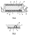
- FIG. 2 illustrates in more detail this second method of manufacturing the sign.
- a mold 41 and a counter-mold 42 a stack comprising, between the insulating layer 3 and each faceplate 1, 2, a composition laminator comprising a layer of glass fibers or carbon 43 in the form of a woven sheet or nonwoven impregnated with a layer of resin thermosetting 44.
- Plates 1 and 2 may not be than a waterproofing coating called "gel-coat".
- layer 3 has been previously provided with the thermal web conductor 7 then of the tubular network 4 in a groove previously formed 46.
- the sheet 7 is therefore interposed between the wall of the groove 46 and the tube 4.
- Counter mold 42 has a sealing lip peripheral 47 pressed against a side wall inside the mold 41.
- a suction orifice 48 of the mold 41 By a suction orifice 48 of the mold 41, the space between the mold 41 and the counter mold 42, so that the counter-mold 42 sinks into the mold 41 according to the arrows 49, thus compressing the stack, in especially the layers of fibers 43 and resin 44.
- These layers mix and flatten to form a stratification interface 51 (FIG. 3) between the layer 3 and each of plates 1 and 2.
- a structural or self-supporting panel say that can serve as a structural element in a construction, for example a roof, without having need of load-bearing framework.
- the conducting sheet 7 On the side of the plate front 1 the conducting sheet 7 is integrated into the structuring interface 51, integral with the veil resin and fiber and allowed by its structure openwork with the resin to impregnate the foam of the layer 3.
- the resin directly secures the plate 1 with layer 3.
- the front plate 1 is preferably coated on its front face 9 of a paint or other coating absorbing solar radiation and transforming it into heat with a tendency as reduced as possible to produce re-emitted radiation.
- the front plate 1 is preferably made of a material with good insulation qualities thermal to prevent heat from escaping through any supporting structures of the panel, such as metallic or other frames. Polyester reinforced with fiberglass suitable for making the plate frontal 1 by giving it both the qualities thermal insulation that has just been exposed and desirable mechanical strength.
- each bundle 4 thus has an upper end 14 and a lower end 16 between which the bundle 4 includes for each panel a single tube shaped like a serpentine formed by horizontal segments interconnected by 180 ° turns, preferably substantially semicircular.
- the extremities 16 are connected to an outlet 17 above level 18 of a fluid tank coolant 19.
- a pump 21 is immersed in the tank 19, as well as its inlet orifice 22.
- the discharge 23 of the pump is connected to the upper ends 14 of the tubular bundles 4.
- the pump 21 takes heat transfer fluid from the tank 19 and circulates it in the direction indicated by arrows P towards the upper ends 14 then through the beams 4 to the ends lower 16 and from there via exit 17 into the tank 19.
- the tank 19 can serve as a hot spring for example for a central heating installation.
- the tank 19 can be very large and be constituted in particular by a swimming pool whose water, which is to be heated, serves as a heat transfer fluid sense of invention.
- the roof 12 can then be a shelter roof to side of the pool, where even, so particularly preferred, a roof according to WO-A-97 20 114, movable between a cover position hermetic of the swimming pool and a position of shelter beside of it.
- the roof refreshed by the thermal sampling is more effective in protecting people below.
- the pump 21 is typically of the centrifugal type or other rotor-turbine type and more generally of a type in which intake 22 and discharge 23 are in communication with each other, at least when the pump is stopped. So as soon as we stop pump 21, the whole system is drained by siphon in the opposite direction (arrows V) from the direction of pumping, i.e. from outlet 17 to lower ends 16 then through the beams 4 to the upper ends 14 and from there to through the outlet 23, the pump 21 and the orifice 22. The risk of freezing when the device is stopped is avoided and the fluid coolant can simply consist of the water.
- Thermostatic means are provided for regulating the temperature of the tank water 19.
- a thermostatic probe 24 is placed in contact thermal with the heat transfer fluid in the tank 19.
- a control unit 26 receives the signal from the probe 24, and compares it with a high threshold SH predetermined in a comparator 27, and cuts the operation of pump 21 when the temperature recorded by probe 24 is greater than the SH threshold, at by means of a switch 28. This avoids heating excessively fluid, especially if it is a swimming pool whose water should not, in general, exceed a moderate temperature of 30 to 35 ° C.
- thermostatic probe 29 is placed in contact thermal with the faceplate 1, and preferably with the thermally conductive sheet 7.
- the control unit 26 receives the signal from the probe 29, compares it with a low threshold SB in a comparator 31, and cuts the operation of the pump 21 by means of switch 28 when the temperature read by the probe is below the low threshold predetermined, higher than freezing temperature heat transfer fluid.
- the low threshold SB is equal to the temperature of the fluid coolant detected by probe 24, whose signal is sent to the negative terminal of comparator 31.
- the device only works when is actually able to heat the water of the tank 19.
- Realization in the form of autonomous panels as shown in figure 1 is not essential: we could for example fix the face back of thermally insulating layer 3 against a supporting structure such as a wall, a slab of roof.
- the tube bundle 4 is made up of a single tube arranged in a serpentine as shown in Figure 4. It has indeed been found that the flow rate thus obtained is enough to collect solar energy and we avoid costs and risks of leakage resulting from multiples welds or fittings that result from bundles multiple tubes mounted in parallel. For better heat transfers but with a higher cost, the beam could be made of metal such as the copper.
- the heat transfer fluid collection below the outlet 17 is the same as that in which the orifice is bathed intake 22 of the pump.
- the probe 24 could, depending on the applications, be placed elsewhere, for example at exit 17 of the network or in contact with a separate use structure tank 19.
- the thermally conductive sheet 7 can be something other than a fence. It can be for example a layer of heat conducting fibers, woven or non-woven, in particular of carbon.
Landscapes
- Engineering & Computer Science (AREA)
- Chemical & Material Sciences (AREA)
- General Engineering & Computer Science (AREA)
- Mechanical Engineering (AREA)
- Physics & Mathematics (AREA)
- Thermal Sciences (AREA)
- Sustainable Energy (AREA)
- Combustion & Propulsion (AREA)
- Sustainable Development (AREA)
- Life Sciences & Earth Sciences (AREA)
- Dispersion Chemistry (AREA)
- Photovoltaic Devices (AREA)
- Laminated Bodies (AREA)
- Building Environments (AREA)
- Roof Covering Using Slabs Or Stiff Sheets (AREA)
- Tents Or Canopies (AREA)
Description
- une plaque frontale située du côté exposé au soleil ;
- une couche thermiquement isolante adjacente à un côté arrière de la plaque frontale, opposé à l'exposition au soleil;
- un faisceau tubulaire pour la circulation d'un fluide caloporteur, ce faisceau étant interposé entre la plaque frontale et la couche isolante; et
- une nappe thermiquement conductrice interposée entre la plaque frontale et la couche thermiquement isolante et qui est en liaison thermique avec la plaque frontale et avec le faisceau tubulaire;
- un réservoir de fluide caloporteur;
- une pompe ayant une admission plongée dans le fluide caloporteur du réservoir; et
- un panneau incorporant un faisceau tubulaire pour le fluide caloporteur, le panneau étant disposé selon un angle par rapport à l'horizontale de façon que le faisceau tubulaire ait une extrémité supérieure raccordée au refoulement de la pompe, et une extrémité inférieure débouchant librement au-dessus du niveau de fluide dans le réservoir.
- le dispositif de collecte d'énergie solaire comprend des moyens thermostatiques pour couper le fonctionnement de la pompe lorsqu'une température d'utilisation relevée, telle que par exemple la température du fluide caloporteur dans le réservoir, dépasse un seuil haut, et/ou pour couper le fonctionnement de la pompe lorsque la température de la plaque frontale est inférieure à un seuil bas.
- des moyens sont prévus pour faire varier le seuil bas en fonction d'une température d'utilisation relevée, telle que par exemple la température du fluide caloporteur en-dehors du réseau tubulaire et en particulier dans le réservoir.
- le réservoir est une piscine.
- la figure 1 est une vue en coupe et perspective d'un panneau selon l'invention;
- la figure 2 est une vue en coupe transversale illustrant un stade du procédé de fabrication d'un panneau solaire selon l'invention;
- la figure 3 est une vue d'un détail du panneau, en coupe; et
- la figure 4 est une vue d'un dispositif de collecte selon l'invention.
- épaisseur des plaques 1 et 2: environ 1 à 2mm;
- épaisseur de la couche isolante 3: environ 60mm;
- faisceau tubulaire en caoutchouc naturel et/ou synthétique, diamètre extérieur : 6mm, diamètre intérieur : 4mm;
- espacement entre les éléments parallèles du faisceau tubulaire: environ 50mm.
Claims (24)
- Panneau solaire, comprenant :caractérisé en ce que la nappe thermiquement conductrice (7) est perméable à un agent de solidarisation (44) de la plaque frontale (1) avec la couche thermiquement isolante (3) et fait partie intégrante d'une interface de stratification (51) de la plaque frontale (1) avec la couche thermiquement isolante (3).une plaque frontale (1) située du côté exposé au soleil ;une couche thermiquement isolante (3) adjacente à un côté arrière de la plaque frontale, opposé à l'exposition au soleil;un faisceau tubulaire (4) pour la circulation d'un fluide caloporteur, ce faisceau étant interposé entre la plaque frontale (9) et la couche isolante (3); etune nappe thermiquement conductrice (7) interposée entre la plaque frontale (1) et la couche thermiquement isolante (3) et qui est en liaison thermique avec la plaque frontale (1) et avec le faisceau tubulaire (4);
- Panneau selon la revendication 1, caractérisé en ce que l'interface de stratification (51) comprend une nappe de fibres (43), tissée ou non-tissée.
- Panneau selon la revendication 1 ou 2, caractérisé en ce que l'agent de solidarisation (44) est une résine thermodurcissable.
- Panneau selon l'une des revendications 1 à 3, caractérisé en ce que la nappe (7) s'étend sensiblement le long de la face arrière de la plaque frontale (1) dans des zones situées entre le faisceau (4), et forme des logements (8) pour contourner localement chaque élément du faisceau (4) en passant entre le faisceau (4) et la couche isolante (3).
- Panneau selon la revendication 4, caractérisé en ce que là où la nappe (7) forme lesdits logements, le reste de l'interface de stratification (51) passe entre la plaque frontale (1) et le faisceau tubulaire (4).
- Panneau selon l'une des revendications 1 à 5, caractérisé en ce que la nappe (7) est un grillage métallique, de préférence en aluminium.
- Panneau selon l'une des revendications 1 à 5, caractérisé en ce que la nappe (7) est une nappe de fibres à bonne conductibilité thermique, de préférence de fibres de carbone.
- Panneau selon l'une des revendications 1 à 7, caractérisé en ce que la plaque frontale (1) est en matière synthétique.
- Panneau selon l'une des revendications 1 à 8, caractérisé en ce que la couche isolante (3) est une mousse synthétique.
- Panneau selon l'une des revendications 1 à 9, caractérisé en ce que le panneau (11) est du type sandwich, la couche isolante (3) étant disposée entre ladite plaque frontale (1) et une plaque arrière (2) fixée à la couche isolante par une seconde interface de stratification.
- Panneau selon l'une des revendications 1 à 10, caractérisé en ce que le faisceau tubulaire (4) comprend au moins un tube disposé en serpentin.
- Panneau selon la revendication 11, caractérisé en ce que le tube est un tube unique comprenant des parties rectilignes reliées entres-elles par des virages à 180°.
- Panneau selon l'une des revendications 1 à 12, caractérisé en ce que le faisceau tubulaire (4) est fait de tube souple, de préférence en matière synthétique.
- Dispositif de collecte d'énergie solaire sous forme thermique, comprenant:caractérisé en ce que le panneau (11) est conforme à l'une des revendications 1 à 13, et en ce que ladite autre extrémité (16) du faisceau débouche librement au-dessus du niveau (18) de fluide dans le réservoir (19), de façon à permettre hors fonctionnement la vidange du fluide caloporteur depuis ladite autre extrémité jusqu'au réservoir à travers la pompe par une circulation inversée du fluide caloporteur.un réservoir de fluide caloporteur (19);une pompe (21) ayant une admission (22) plongée dans le fluide caloporteur du réservoir (19); etun panneau (11) incorporant un faisceau tubulaire (4) pour le fluide caloporteur, le panneau étant disposé selon un angle (13) par rapport à l'horizontale de façon que le faisceau tubulaire (4) ait une extrémité supérieure (14) et une extrémité inférieure (16) dont l'une est raccordée au refoulement (23) de la pompe (21) et l'autre débouche dans le réservoir (19),
- Dispositif de collecte d'énergie solaire selon la revendication 14, caractérisé en ce que le panneau (11) est un panneau de toiture (12).
- Dispositif de collecte d'énergie solaire selon la revendication 14 ou 15, caractérisé en ce que le fluide caloporteur est de l'eau.
- Dispositif de collecte d'énergie solaire selon l'une des revendications 14 à 16, caractérisé en ce qu'il comprend des moyens thermostatiques (24, 27, 28) pour couper le fonctionnement de la pompe lorsqu'une température d'utilisation relevée dépasse un seuil haut (SH).
- Dispositif de collecte d'énergie solaire selon l'une des revendications 14 à 17, caractérisé en ce qu'il comprend des moyens thermostatiques (28, 29, 31) pour couper le fonctionnement de la pompe lorsque la température d'une partie frontale (1) du panneau est inférieure à un seuil bas (SB).
- Dispositif de collecte d'énergie solaire selon la revendication 18, caractérisé en ce qu'il comprend des moyens pour faire varier le seuil bas (SB) en fonction d'une température d'utilisation relevée.
- Dispositif de collecte d'énergie solaire selon l'une des revendications 14 à 19, caractérisé en ce que le réservoir (19) est une piscine.
- Dispositif de collecte selon l'une des revendications 14 à 20, caractérisé en ce que ladite autre extrémité de faisceau est l'extrémité inférieure (16).
- Procédé pour réaliser un panneau selon l'une des revendications 1 à 13, caractérisé en ce qu'on forme dans une face d'un bloc de mousse plat au moins un sillon (6), on place la nappe thermiquement conductrice (7) sur ladite face du bloc, on place un réseau tubulaire (4) dans le sillon (6) alors que la nappe (7) forme des logements épousant la forme du sillon (6), puis on fixe sur ladite face une plaque frontale (1) au moyen d'une interface de stratification.
- Procédé selon la revendication 22, caractérisé en ce qu'on forme le sillon (6) avec une forme sinueuse et on utilise pour le réseau tubulaire (4) un tube souple que l'on forme par son positionnement dans le sillon (6).
- Procédé selon la revendication 22 ou 23, caractérisé en ce qu'on part d'une nappe thermiquement conductrice (7) initialement plane ayant une flexibilité suffisante pour former lesdits logements par la présence de la plaque frontale (1) maintenant le réseau tubulaire (4) dans le sillon (6).
Applications Claiming Priority (3)
| Application Number | Priority Date | Filing Date | Title |
|---|---|---|---|
| FR9805038 | 1998-04-22 | ||
| FR9805038A FR2777984B1 (fr) | 1998-04-22 | 1998-04-22 | Panneau solaire et dispositif de collecte d'energie solaire |
| PCT/FR1999/000853 WO1999054671A1 (fr) | 1998-04-22 | 1999-04-13 | Panneau solaire et dispositif de collecte d'energie solaire |
Publications (2)
| Publication Number | Publication Date |
|---|---|
| EP1073869A1 EP1073869A1 (fr) | 2001-02-07 |
| EP1073869B1 true EP1073869B1 (fr) | 2002-10-16 |
Family
ID=9525538
Family Applications (1)
| Application Number | Title | Priority Date | Filing Date |
|---|---|---|---|
| EP99913393A Expired - Lifetime EP1073869B1 (fr) | 1998-04-22 | 1999-04-13 | Panneau solaire et dispositif de collecte d'energie solaire |
Country Status (12)
| Country | Link |
|---|---|
| US (1) | US6513518B1 (fr) |
| EP (1) | EP1073869B1 (fr) |
| AT (1) | ATE226303T1 (fr) |
| AU (1) | AU745513B2 (fr) |
| CA (1) | CA2329638C (fr) |
| DE (1) | DE69903533T2 (fr) |
| DK (1) | DK1073869T3 (fr) |
| ES (1) | ES2185327T3 (fr) |
| FR (1) | FR2777984B1 (fr) |
| IL (1) | IL139108A0 (fr) |
| PT (1) | PT1073869E (fr) |
| WO (1) | WO1999054671A1 (fr) |
Families Citing this family (34)
| Publication number | Priority date | Publication date | Assignee | Title |
|---|---|---|---|---|
| DE10043295C1 (de) * | 2000-09-02 | 2002-04-25 | Rheinzink Gmbh | Heliothermischer Flachkollektor-Modul |
| US6708687B2 (en) * | 2001-06-12 | 2004-03-23 | James B. Blackmon, Jr. | Thermally controlled solar reflector facet with heat recovery |
| DE20216297U1 (de) | 2002-10-23 | 2003-01-09 | Rheinzink GmbH & Co. KG, 45711 Datteln | Heliothermischer Flachkollektor-Modul in Sandwichbauweise |
| US7234303B2 (en) * | 2003-05-30 | 2007-06-26 | General Electric Company | Polymer roof panel solar energy conversion device |
| US20050051208A1 (en) * | 2003-06-17 | 2005-03-10 | Mount Robert L. | System for transferring heat in a thermoelectric generator system |
| SE526591C2 (sv) * | 2003-10-31 | 2005-10-11 | Tord Olsson | Yttertakskonstruktion med organ för att transportera ett energilagrande medium och ett isoleringsskikt |
| WO2006045239A1 (fr) * | 2004-10-26 | 2006-05-04 | Qun Hua | Plaque collectrice d'energie solaire |
| TWM297974U (en) * | 2006-03-24 | 2006-09-21 | Shr-Shiung Chen | Ventilation device for solar energy roof |
| CA2654373A1 (fr) * | 2006-06-13 | 2007-12-21 | Kingspan Research And Developments Limited | Panneau isolant composite |
| US9663955B2 (en) * | 2006-06-19 | 2017-05-30 | Daniel Efrain Arguelles | Pan tile roofing system |
| ES2310124B1 (es) * | 2007-05-17 | 2009-11-11 | Antonio Molina Alcolea | Elemento energetico estructural. |
| CA2633025A1 (fr) * | 2007-05-30 | 2008-11-30 | Gordon Hogan | Panneau solaire |
| EP2061091B1 (fr) * | 2007-11-14 | 2012-01-11 | Luxin (Green Planet) AG | Plaque de toit ou de façade avec panneaux solaires |
| BE1018017A5 (nl) | 2008-02-26 | 2010-04-06 | Nys Manu | Gelaagde constructie met buizenstelsel. |
| NL2001480C1 (nl) * | 2008-04-14 | 2009-10-15 | Adrianus Andreas Gijsbertus Schiebroek | Dakpaneel voor warmte-uitwisseling. |
| GB0903385D0 (en) * | 2009-02-27 | 2009-04-08 | Sundwel Solar Ltd | Solar thermal collection device and method of manufacture |
| NL1036855C2 (nl) * | 2009-04-15 | 2010-10-18 | Cons Groep B V | Warmtecollector en warmte collecterende dakconstructie. |
| NL2003336C2 (nl) * | 2009-04-15 | 2011-08-11 | Cons Groep B V | Warmtecollector en warmte collecterende dakconstructie. |
| US20100288264A1 (en) * | 2009-05-13 | 2010-11-18 | Zheng Zhang | Modular solar fence system |
| DE102009048000A1 (de) * | 2009-10-01 | 2011-09-15 | Bayer Materialscience Ag | Verbundwerkstoff aus offenzelligem Hartschaum |
| DE102010036383A1 (de) * | 2009-10-07 | 2011-05-26 | Ludger Hambrock | Solarbauelement für Solarthermieanlagen, Solarthermieanlage, Verfahren zum Betreiben einer Solarthermieanlage und Teile eines Solarbauelements für Solarthermieanlage |
| DE102009060398A1 (de) * | 2009-12-22 | 2011-06-30 | Hess, Martin, 85051 | Instrumenten-Schutzgehäuse, insbesondere Instrumentenschutzhaus für elektrische Instrumente und Analysegeräte |
| WO2013133900A2 (fr) * | 2012-03-09 | 2013-09-12 | Donald Bennett Hilliard | Appareil thermique solaire |
| PL2526349T3 (pl) | 2010-01-18 | 2021-12-06 | Tigi Ltd. | System do ograniczania temperatury w uszczelnionym kolektorze słonecznym |
| US9644865B2 (en) * | 2010-03-23 | 2017-05-09 | Solarreserve Technology, Llc | Thermal shield for solar receiver |
| DE202011108308U1 (de) | 2011-11-25 | 2012-02-27 | Suncol Oy | Baumodul |
| EP2613103A1 (fr) * | 2012-01-04 | 2013-07-10 | Pebüso-Betonwerke H. Büscher GmbH & Co. KG | Pavé solaire |
| GB2498737B (en) * | 2012-01-24 | 2017-04-19 | Future Energy Source Ltd | A solar energy capture system |
| US20130269756A1 (en) * | 2012-03-14 | 2013-10-17 | Frank Pao | Tall Slate BITERS |
| US9267710B2 (en) | 2012-04-18 | 2016-02-23 | Solight Solar, Inc. | Solar thermal collectors and thin plate heat exchangers for solar applications |
| EP2789761A1 (fr) * | 2013-04-08 | 2014-10-15 | European Investment Group B.V. | Élément de protection et de revêtement de bâtiments |
| US11035130B1 (en) | 2019-02-01 | 2021-06-15 | Daniel Efrain Arguelles | Synthetic mechanically attached roof underlayment system |
| DE102020114925A1 (de) | 2020-06-04 | 2021-12-09 | Ulrich Loser | Vorrichtung und Verfahren zur Erwärmung eines Fluids |
| DE202020103229U1 (de) | 2020-06-04 | 2021-09-07 | Ulrich Loser | Vorrichtung zur Erwärmung eines Fluids |
Family Cites Families (16)
| Publication number | Priority date | Publication date | Assignee | Title |
|---|---|---|---|---|
| US3952725A (en) * | 1974-06-24 | 1976-04-27 | Edmondson William B | Solar water heater |
| GB1467039A (en) * | 1975-05-22 | 1977-03-16 | Oconnell J | Heat absorption and/or radiation panels |
| US4060071A (en) * | 1976-06-17 | 1977-11-29 | Solar Energy Dynamics Corporation | Solar collector for solar heating systems |
| FR2384215A1 (fr) | 1977-03-18 | 1978-10-13 | Elf Union | Structure de toiture solaire et ses applications |
| US4072262A (en) * | 1977-04-04 | 1978-02-07 | Kennecott Copper Corporation | Method of fabricating a solar heating unit |
| GB1572680A (en) * | 1977-08-11 | 1980-07-30 | United Wire Group Ltd | Heat transfer elements |
| US4205658A (en) * | 1977-10-06 | 1980-06-03 | Clark Peter C | Heat transfer panel |
| FR2409463A1 (fr) * | 1977-11-17 | 1979-06-15 | Finimetal Finissage Produi Met | Capteur solaire |
| FR2428224A2 (fr) * | 1978-06-06 | 1980-01-04 | Martel Catala & Cie Ets | Perfectionnements aux faisceaux tubulaires et a leur procede de fabrication |
| CA1115608A (fr) * | 1979-06-04 | 1982-01-05 | John M. Stewart | Systemes de chauffage a l'energie solaire |
| US4381763A (en) * | 1980-01-28 | 1983-05-03 | Kahl Karl H | Low cost, low pressure, solar heated fence surrounding a swimming pool |
| DE3110826A1 (de) * | 1980-03-19 | 1982-02-11 | Mörk KG Baustoffe, 7730 Villingen-Schwenningen | Absorberplattenelement |
| SE434186B (sv) * | 1982-05-27 | 1984-07-09 | Inga Sundquist | Solmodul |
| US4644935A (en) * | 1984-09-21 | 1987-02-24 | Rayflow Corp. | Solar heater control |
| US4911353A (en) * | 1986-03-31 | 1990-03-27 | David Deakin | Solar collector having absorber plate formed by spraying molten metal |
| US5794611A (en) * | 1996-05-24 | 1998-08-18 | Refrigeration Research, Inc. | Solar collector |
-
1998
- 1998-04-22 FR FR9805038A patent/FR2777984B1/fr not_active Expired - Lifetime
-
1999
- 1999-04-13 PT PT99913393T patent/PT1073869E/pt unknown
- 1999-04-13 AU AU31532/99A patent/AU745513B2/en not_active Ceased
- 1999-04-13 ES ES99913393T patent/ES2185327T3/es not_active Expired - Lifetime
- 1999-04-13 AT AT99913393T patent/ATE226303T1/de not_active IP Right Cessation
- 1999-04-13 EP EP99913393A patent/EP1073869B1/fr not_active Expired - Lifetime
- 1999-04-13 CA CA002329638A patent/CA2329638C/fr not_active Expired - Fee Related
- 1999-04-13 US US09/674,030 patent/US6513518B1/en not_active Expired - Fee Related
- 1999-04-13 IL IL13910899A patent/IL139108A0/xx not_active IP Right Cessation
- 1999-04-13 WO PCT/FR1999/000853 patent/WO1999054671A1/fr not_active Ceased
- 1999-04-13 DE DE69903533T patent/DE69903533T2/de not_active Expired - Fee Related
- 1999-04-13 DK DK99913393T patent/DK1073869T3/da active
Also Published As
| Publication number | Publication date |
|---|---|
| EP1073869A1 (fr) | 2001-02-07 |
| DE69903533T2 (de) | 2003-07-10 |
| IL139108A0 (en) | 2001-11-25 |
| DK1073869T3 (da) | 2003-02-10 |
| CA2329638A1 (fr) | 1999-10-28 |
| FR2777984A1 (fr) | 1999-10-29 |
| ES2185327T3 (es) | 2003-04-16 |
| US6513518B1 (en) | 2003-02-04 |
| FR2777984B1 (fr) | 2000-07-28 |
| AU3153299A (en) | 1999-11-08 |
| ATE226303T1 (de) | 2002-11-15 |
| PT1073869E (pt) | 2003-03-31 |
| DE69903533D1 (de) | 2002-11-21 |
| WO1999054671A1 (fr) | 1999-10-28 |
| AU745513B2 (en) | 2002-03-21 |
| CA2329638C (fr) | 2007-04-10 |
Similar Documents
| Publication | Publication Date | Title |
|---|---|---|
| EP1073869B1 (fr) | Panneau solaire et dispositif de collecte d'energie solaire | |
| FR2461901A1 (fr) | Capteur d'energie solaire, chauffe-eau et dispositif de chauffage avec pompe a chaleur comportant ledit capteur | |
| EP2118581A1 (fr) | Panneau solaire pouvant être installé en toiture | |
| FR2976305A1 (fr) | Systeme de fixation et d'etancheite pour la realisation d'une toiture solaire, et toiture solaire obtenue | |
| FR2553872A1 (fr) | Chauffe-eau solaire | |
| EP2286158B1 (fr) | Dispositif échangeur de chaleur double flux | |
| EP2623909B1 (fr) | Panneau photovoltaïque à récupération thermique | |
| CH632833A5 (en) | Element which absorbs solar radiation | |
| EP2299198B1 (fr) | Dispositif de chauffage et/ou de rafraichissement d'un volume de fluide contenu dans une enceinte, en particulier d'un volume d'eau contenu dans une piscine, et piscine équipée d'un tel dispositif | |
| EP1709279B1 (fr) | Volet integrant un convertisseur solaire a air | |
| EP0289438B1 (fr) | Absorbeur-stockeur d'énergie solaire | |
| EP3688243B1 (fr) | Élément de construction préfabriqué, bâtiment comprenant ledit élément de construction et procédé de fabrication de l'élément de construction associé | |
| CH701001A2 (fr) | Citerne solaire. | |
| FR2516217A1 (fr) | Capteur solaire plan | |
| EP4214453B1 (fr) | Système de chauffage solaire | |
| GB2454180A (en) | A cover and solar heater for a swimming pool | |
| FR2463903A1 (fr) | Element chauffant solaire et procede de fabrication d'une lentille pour cet element | |
| FR2460454A1 (fr) | Element absorbeur de radiations solaires | |
| FR2482708A1 (fr) | Installation a capteur solaire et procede de fabrication d'un tel capteur | |
| FR2978298A1 (fr) | Module de production d'energie photovoltaique et thermique a partir du rayonnement solaire, et installation equipee de tels modules. | |
| FR2493484A1 (fr) | Structure de capteur solaire a chassis integre modulaire assemblable | |
| FR2610098A1 (fr) | Panneaux sandwiches chauffants et (ou) refroidissants | |
| FR3075944A1 (fr) | Systeme de regulation thermique | |
| WO1984000205A1 (fr) | Capteur solaire a haut rendement | |
| FR2485708A1 (fr) | Perfectionnement aux echangeurs thermiques destines alternativement a chauffer ou refroidir un fluide par l'action des phenomenes climatiques |
Legal Events
| Date | Code | Title | Description |
|---|---|---|---|
| PUAI | Public reference made under article 153(3) epc to a published international application that has entered the european phase |
Free format text: ORIGINAL CODE: 0009012 |
|
| 17P | Request for examination filed |
Effective date: 20001114 |
|
| AK | Designated contracting states |
Kind code of ref document: A1 Designated state(s): AT BE CH DE DK ES FR GB GR IE IT LI NL PT SE |
|
| 17Q | First examination report despatched |
Effective date: 20010504 |
|
| GRAG | Despatch of communication of intention to grant |
Free format text: ORIGINAL CODE: EPIDOS AGRA |
|
| GRAG | Despatch of communication of intention to grant |
Free format text: ORIGINAL CODE: EPIDOS AGRA |
|
| GRAH | Despatch of communication of intention to grant a patent |
Free format text: ORIGINAL CODE: EPIDOS IGRA |
|
| GRAH | Despatch of communication of intention to grant a patent |
Free format text: ORIGINAL CODE: EPIDOS IGRA |
|
| GRAA | (expected) grant |
Free format text: ORIGINAL CODE: 0009210 |
|
| AK | Designated contracting states |
Kind code of ref document: B1 Designated state(s): AT BE CH DE DK ES FR GB GR IE IT LI NL PT SE |
|
| REF | Corresponds to: |
Ref document number: 226303 Country of ref document: AT Date of ref document: 20021115 Kind code of ref document: T |
|
| REG | Reference to a national code |
Ref country code: GB Ref legal event code: FG4D Free format text: NOT ENGLISH |
|
| REG | Reference to a national code |
Ref country code: CH Ref legal event code: EP |
|
| REG | Reference to a national code |
Ref country code: IE Ref legal event code: FG4D Free format text: FRENCH |
|
| REF | Corresponds to: |
Ref document number: 69903533 Country of ref document: DE Date of ref document: 20021121 |
|
| REG | Reference to a national code |
Ref country code: CH Ref legal event code: NV Representative=s name: ABREMA AGENCE BREVETS ET MARQUES GANGUILLET & HUMP |
|
| REG | Reference to a national code |
Ref country code: DK Ref legal event code: T3 |
|
| GBT | Gb: translation of ep patent filed (gb section 77(6)(a)/1977) |
Effective date: 20030203 |
|
| REG | Reference to a national code |
Ref country code: GR Ref legal event code: EP Ref document number: 20030400131 Country of ref document: GR |
|
| REG | Reference to a national code |
Ref country code: PT Ref legal event code: SC4A Free format text: AVAILABILITY OF NATIONAL TRANSLATION Effective date: 20030115 |
|
| REG | Reference to a national code |
Ref country code: ES Ref legal event code: FG2A Ref document number: 2185327 Country of ref document: ES Kind code of ref document: T3 |
|
| PLBE | No opposition filed within time limit |
Free format text: ORIGINAL CODE: 0009261 |
|
| STAA | Information on the status of an ep patent application or granted ep patent |
Free format text: STATUS: NO OPPOSITION FILED WITHIN TIME LIMIT |
|
| 26N | No opposition filed |
Effective date: 20030717 |
|
| PGFP | Annual fee paid to national office [announced via postgrant information from national office to epo] |
Ref country code: ES Payment date: 20080429 Year of fee payment: 10 Ref country code: DK Payment date: 20080411 Year of fee payment: 10 Ref country code: DE Payment date: 20080419 Year of fee payment: 10 Ref country code: CH Payment date: 20080415 Year of fee payment: 10 |
|
| PGFP | Annual fee paid to national office [announced via postgrant information from national office to epo] |
Ref country code: AT Payment date: 20080415 Year of fee payment: 10 |
|
| PGFP | Annual fee paid to national office [announced via postgrant information from national office to epo] |
Ref country code: PT Payment date: 20080402 Year of fee payment: 10 Ref country code: IT Payment date: 20080424 Year of fee payment: 10 Ref country code: BE Payment date: 20080522 Year of fee payment: 10 |
|
| PGFP | Annual fee paid to national office [announced via postgrant information from national office to epo] |
Ref country code: SE Payment date: 20080414 Year of fee payment: 10 Ref country code: NL Payment date: 20080415 Year of fee payment: 10 Ref country code: IE Payment date: 20080424 Year of fee payment: 10 |
|
| PGFP | Annual fee paid to national office [announced via postgrant information from national office to epo] |
Ref country code: GB Payment date: 20080418 Year of fee payment: 10 |
|
| PGFP | Annual fee paid to national office [announced via postgrant information from national office to epo] |
Ref country code: GR Payment date: 20080417 Year of fee payment: 10 |
|
| REG | Reference to a national code |
Ref country code: PT Ref legal event code: MM4A Free format text: LAPSE DUE TO NON-PAYMENT OF FEES Effective date: 20091013 |
|
| BERE | Be: lapsed |
Owner name: *TOUTENKAMION Effective date: 20090430 |
|
| REG | Reference to a national code |
Ref country code: CH Ref legal event code: PL |
|
| REG | Reference to a national code |
Ref country code: DK Ref legal event code: EBP |
|
| EUG | Se: european patent has lapsed | ||
| GBPC | Gb: european patent ceased through non-payment of renewal fee |
Effective date: 20090413 |
|
| NLV4 | Nl: lapsed or anulled due to non-payment of the annual fee |
Effective date: 20091101 |
|
| REG | Reference to a national code |
Ref country code: FR Ref legal event code: ST Effective date: 20091231 |
|
| PG25 | Lapsed in a contracting state [announced via postgrant information from national office to epo] |
Ref country code: LI Free format text: LAPSE BECAUSE OF NON-PAYMENT OF DUE FEES Effective date: 20090430 Ref country code: DE Free format text: LAPSE BECAUSE OF NON-PAYMENT OF DUE FEES Effective date: 20091103 Ref country code: CH Free format text: LAPSE BECAUSE OF NON-PAYMENT OF DUE FEES Effective date: 20090430 Ref country code: AT Free format text: LAPSE BECAUSE OF NON-PAYMENT OF DUE FEES Effective date: 20090413 |
|
| REG | Reference to a national code |
Ref country code: IE Ref legal event code: MM4A |
|
| PG25 | Lapsed in a contracting state [announced via postgrant information from national office to epo] |
Ref country code: NL Free format text: LAPSE BECAUSE OF NON-PAYMENT OF DUE FEES Effective date: 20091101 |
|
| PG25 | Lapsed in a contracting state [announced via postgrant information from national office to epo] |
Ref country code: PT Free format text: LAPSE BECAUSE OF NON-PAYMENT OF DUE FEES Effective date: 20091013 |
|
| PG25 | Lapsed in a contracting state [announced via postgrant information from national office to epo] |
Ref country code: IE Free format text: LAPSE BECAUSE OF NON-PAYMENT OF DUE FEES Effective date: 20090413 Ref country code: GB Free format text: LAPSE BECAUSE OF NON-PAYMENT OF DUE FEES Effective date: 20090413 Ref country code: FR Free format text: LAPSE BECAUSE OF NON-PAYMENT OF DUE FEES Effective date: 20091222 Ref country code: DK Free format text: LAPSE BECAUSE OF NON-PAYMENT OF DUE FEES Effective date: 20090430 |
|
| PGFP | Annual fee paid to national office [announced via postgrant information from national office to epo] |
Ref country code: FR Payment date: 20080428 Year of fee payment: 10 |
|
| PG25 | Lapsed in a contracting state [announced via postgrant information from national office to epo] |
Ref country code: BE Free format text: LAPSE BECAUSE OF NON-PAYMENT OF DUE FEES Effective date: 20090430 |
|
| REG | Reference to a national code |
Ref country code: ES Ref legal event code: FD2A Effective date: 20090414 |
|
| PG25 | Lapsed in a contracting state [announced via postgrant information from national office to epo] |
Ref country code: GR Free format text: LAPSE BECAUSE OF NON-PAYMENT OF DUE FEES Effective date: 20091104 |
|
| PG25 | Lapsed in a contracting state [announced via postgrant information from national office to epo] |
Ref country code: ES Free format text: LAPSE BECAUSE OF NON-PAYMENT OF DUE FEES Effective date: 20090414 |
|
| PG25 | Lapsed in a contracting state [announced via postgrant information from national office to epo] |
Ref country code: IT Free format text: LAPSE BECAUSE OF NON-PAYMENT OF DUE FEES Effective date: 20090413 |
|
| PG25 | Lapsed in a contracting state [announced via postgrant information from national office to epo] |
Ref country code: SE Free format text: LAPSE BECAUSE OF NON-PAYMENT OF DUE FEES Effective date: 20090414 |