EP1074006B1 - Münzpfandschloss für einkaufswagen - Google Patents
Münzpfandschloss für einkaufswagen Download PDFInfo
- Publication number
- EP1074006B1 EP1074006B1 EP99927675A EP99927675A EP1074006B1 EP 1074006 B1 EP1074006 B1 EP 1074006B1 EP 99927675 A EP99927675 A EP 99927675A EP 99927675 A EP99927675 A EP 99927675A EP 1074006 B1 EP1074006 B1 EP 1074006B1
- Authority
- EP
- European Patent Office
- Prior art keywords
- coin
- key
- deposit lock
- chamber
- control
- Prior art date
- Legal status (The legal status is an assumption and is not a legal conclusion. Google has not performed a legal analysis and makes no representation as to the accuracy of the status listed.)
- Expired - Lifetime
Links
- 229920003023 plastic Polymers 0.000 claims description 8
- 239000004033 plastic Substances 0.000 claims description 8
- 230000000903 blocking effect Effects 0.000 claims description 6
- 239000000463 material Substances 0.000 claims description 3
- 230000000295 complement effect Effects 0.000 claims description 2
- 238000010276 construction Methods 0.000 claims description 2
- 238000006073 displacement reaction Methods 0.000 claims description 2
- 210000000080 chela (arthropods) Anatomy 0.000 claims 1
- 230000000717 retained effect Effects 0.000 claims 1
- 238000003780 insertion Methods 0.000 description 3
- 230000037431 insertion Effects 0.000 description 3
- 238000004519 manufacturing process Methods 0.000 description 3
- 239000002184 metal Substances 0.000 description 2
- 210000002105 tongue Anatomy 0.000 description 2
- 238000004873 anchoring Methods 0.000 description 1
- 230000015572 biosynthetic process Effects 0.000 description 1
- 230000001419 dependent effect Effects 0.000 description 1
- 210000003128 head Anatomy 0.000 description 1
- 238000001746 injection moulding Methods 0.000 description 1
- 230000003993 interaction Effects 0.000 description 1
- 238000000034 method Methods 0.000 description 1
- 210000001331 nose Anatomy 0.000 description 1
- 239000000243 solution Substances 0.000 description 1
Images


Classifications
-
- G—PHYSICS
- G07—CHECKING-DEVICES
- G07F—COIN-FREED OR LIKE APPARATUS
- G07F7/00—Mechanisms actuated by objects other than coins to free or to actuate vending, hiring, coin or paper currency dispensing or refunding apparatus
- G07F7/06—Mechanisms actuated by objects other than coins to free or to actuate vending, hiring, coin or paper currency dispensing or refunding apparatus by returnable containers, i.e. reverse vending systems in which a user is rewarded for returning a container that serves as a token of value, e.g. bottles
- G07F7/0618—Mechanisms actuated by objects other than coins to free or to actuate vending, hiring, coin or paper currency dispensing or refunding apparatus by returnable containers, i.e. reverse vending systems in which a user is rewarded for returning a container that serves as a token of value, e.g. bottles by carts
- G07F7/0654—Mechanisms actuated by objects other than coins to free or to actuate vending, hiring, coin or paper currency dispensing or refunding apparatus by returnable containers, i.e. reverse vending systems in which a user is rewarded for returning a container that serves as a token of value, e.g. bottles by carts in which the lock functions according to a "pinching of the token" principle, i.e. the token is held between two members
Definitions
- the invention relates to a coin deposit lock, in particular for use in shopping trolleys.
- the empty shopping cart in turn goes to the designated one Shopping cart row is brought and inserted into this row can, in reverse order described with the next shopping cart firmly connected key entered into the coin deposit lock again and the inserted coin will be released for withdrawal.
- the document GB-A-2276482 describes a coin deposit lock for shopping carts Coin chamber and key chamber with at least one functional part, which is introduced releases a key to a coin and vice versa, the functional part being a turned part, its front area to the coin chamber and its rear area to the Key chamber adjoins,
- the document US-A-5377806 describes a coin deposit lock for shopping carts Coin chamber and key chamber with at least one functional part, which is introduced releases a key to a coin and vice versa, using an in Direction of movement of the coin and key of this sliding control part, wherein the functional part is a turned part, and its front area to the coin chamber and whose rear area adjoins the key chamber, the rotating part above Control contours is guided in a slot of the key that when the Control part between two end positions a rotation of the rotating part between two End angular positions are done.
- a system known from EP 0 686 294 B1 has four functional parts for performing the operations described above on when a coin is inserted into a coin chamber or in a key chamber held key that connects to the next shopping cart manufactures, releases and vice versa; the key consists of a metal functional part for interaction with the functional part and the locking bolt, as well a plastic handle section enveloping this metal functional part.
- the basic idea of the invention is therefore first that the number of components used is further minimized, these components by their respective Inner contours or outer contours the movement sequences within the coin deposit lock between the respective end positions, locking position and release position, control independently.
- control cam (s) in the turned part (s) creates space for a large clear cross section within the key chamber and thus for one Key with the appropriate cross-section, as it is made of a plastic key Stability reasons is required.
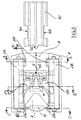
- FIG. 1 shows the preferred embodiment of the invention Coin deposit lock in its two end positions, each in a top view ( Figure 1 and Figure 3) and four sectional views (Figure 2 and Figure 4), being in the top view 1 and 3, the top cover 101 of the housing 1 is removed is.
- Figure 1 and Figure 3 shows the preferred embodiment of the invention
- Figure 2 and Figure 4 the top cover 101 of the housing 1 is removed is.
- the bottom of FIG. 1 is thus visible lower cover 102 shown hatched.
- the lower cover 102 consists of an essentially rectangular plastic plate, in the edge regions of which bearings N are introduced, which are used to hold serves two rollers 2A, 2B, which are parallel to the side walls of the housing 1.
- the control part 5 consists of two identical control elements 5A, 5B, which means a spring in the direction of the rollers 2A, 2B are pushed apart.
- the coin chamber 3 which faces the coin 13 the two control elements 5A, 5B designed like pliers or fork, such that they can be operated by the coin 13 when it is inserted.
- the rear section of the control elements 5A, 5B is complementary to the end face of the key 12 formed such that an application of the controls 5A, 5B when the key 12 is inserted.
- rollers 2A, 2B and the control elements 5A, 5B are identical in construction and are mirror images held to the longitudinal axis of the housing 1, in so far also a symmetrical function given is.
- the two rollers 2A, 2B have locking contours 8 and 9 near their end faces that are circumferentially offset from each other by about the head angle.
- This Locking contours are in the illustrated embodiment as noses or tongues trained and point towards the coin chamber 3 or key chamber 4th
- first end position of the coin deposit lock ( Figures 1 and 2) is the Key 12 in the key chamber 4, in this position are the two control contours 6A, 6B in the position shown; the first end position of the control part 5 corresponds to a first angular position of the two rollers 2A, 2B.
- first end position of the control part 5 corresponds to a first angular position of the two rollers 2A, 2B.
- this angular position are the locking contours 9A, 9B in the recesses 12A, 12B of the key 12 pivoted in the area of the key chamber 4, so that the key 12 is not can be removed from the coin deposit lock and consequently the one with the coin deposit lock connected shopping cart is chained to the shopping cart row.
- Tongue 12C first a space 5C between the two spaced rear areas of the two control elements 5A, 5B and pushes them so far apart, until the rear two knobs 10A, 10B in the longitudinal axis of the housing Reaching section of the control trough 11.
Landscapes
- Physics & Mathematics (AREA)
- General Physics & Mathematics (AREA)
- Handcart (AREA)
- Coin-Freed Apparatuses For Hiring Articles (AREA)
- Control Of Vending Devices And Auxiliary Devices For Vending Devices (AREA)
Description
- Figur 1:
- Eine Aufsicht auf das geöffnete Münzpfandschloß in seiner ersten Endposition bei eingeführtem Schlüssel,
- Figur 2:
- vier Schnittdarstellungen durch das Münzpfandschloß gemäß Figur 1,
- Figur 3:
- eine Aufsicht auf das geöffnete Münzpfandschloß in seiner zweiten Endposition bei eingeführter Münze,
- Figur 4:
- vier Schnittdarstellungen durch das Münzpfandschloß gemäß Figur 3.
Claims (10)
- Münzpfandschloß für Einkaufswagen, mit Münzkammer (3) und Schlüsselkammer (4) mit mindestens einem Funktionsteil, das/die bei Einführung einer Münze (13) einen Schlüssel (12) freigibt/freigeben und umgekehrt, unter Verwendung eines in Bewegungsrichtung von Münze (13) und Schlüssel (12) von diesen verschiebbaren Steuerteils (5), wobei das Funktionsteil ein Drehteil (2) ist, dessen Drehachse zumindest teilweise parallel zur Bewegungsrichtung (F) des Steuerteils (5) liegt, und dessen vorderer Bereich an die Münzkammer (3) und dessen hinterer Bereich an die Schlüsselkammer (4) angrenzt, und wobei seitlich vom Drehteil das Steuerteil (5) angeordnet ist, das über Steuerkonturen (6A,6B) in einer zum Teil spiralförmigen Steuerkurve (7A,7B) im Drehteil (2) derart geführt ist, daß bei einer Verschiebung des Steuerteils (5) zwischen zwei Endpositionen eine Drehung des Drehteils (2) zwischen zwei End-Winkelpositionen (α1,α2) erfolgt, in denen eine wechselweise Blockierung von Münze (13) und Schlüssel (12) dadurch erfolgt, daß Sperrkonturen (8A,B,9A,B) des Drehteils in die Bewegungsbahn von Münze (13) oder Schlüssel (12) einschwenken.
- Münzpfandschloß nach Anspruch 1, dadurch gekennzeichnet, daß als Drehteil (2) zwei parallel zueinander gelagerte zylindrische Walzen (2A,2B) vorgesehen sind, die die Münzkammer (3), das Steuerteil und die Schlüsselkammer (4) zwischen sich einschließen.
- Münzpfandschloß nach Anspruch 2, dadurch gekennzeichnet, daß das Steuerteil (5) aus baugleichen Steuerelementen (5A,5B) besteht, die voneinander weg in Richtung zum Mantel der Walzen (2A,2B) gedrückt werden.
- Münzpfandschloß nach Anspruch 3, dadurch gekennzeichnet, daß die beiden Steuerelemente (5A,5B) über Noppen (10A,10B) verfügen, die in einer Steuerrinne (11) im Gehäuse (1) derart geführt sind, daß bei Einwirkung von Münze (13) oder Schlüssel (12) auf das Steuerteil (5) eine Blockierung in der jeweiligen Endposition gelöst wird und das Steuerteil (5) verschoben werden kann.
- Münzpfandschloß nach Anspruch 1 bis Anspruch 4, dadurch gekennzeichnet, daß Walzen (2A,2B) und Steuerelemente (5A,5B) baugleich sind und spiegelbildlich zueinander im Gehäuse (1) gehalten sind.
- Münzpfandschloß nach Anspruch 3, dadurch gekennzeichnet, daß zur Beaufschlagung der beiden Steuerelemente (5A,5B) eine Feder ( 15 ) eingelegt ist.
- Münzpfandschloß nach Anspruch 3, dadurch gekennzeichnet, daß zur Beaufschlagung der beiden Steuerelemente (5A,5B) diese aus Kunststoff gefertigt sind, wobei ein Federelement angespritzt ist.
- Münzpfandschloß nach Anspruch 3, dadurch gekennzeichnet, daß die beiden Steuerelemente (5A,5B) zur Betätigung durch Münze (13) oder Schlüssel (12) zangenähnlich ausgestaltet sind, mit Zangenarmen, die von der Münze (13) betätigt werden können, und rückwärtigen Abschnitten, die mit dem Schlüssel (12) abschnittsweise formschlüssig komplementär gestaltet sind.
- Münzpfandschloß nach Anspruch 3, dadurch gekennzeichnet, daß das Steuerteil (5) einstückig ausgebildet ist, mit beweglichen Arretierungselementen im Gehäuse (1).
- Münzpfandschloß nach den vorherigen Ansprüchen, dadurch gekennzeichnet, daß sämtliche Bauteile aus Kunststoff sind.
Applications Claiming Priority (3)
| Application Number | Priority Date | Filing Date | Title |
|---|---|---|---|
| DE19817380 | 1998-04-20 | ||
| DE19817380A DE19817380A1 (de) | 1998-04-20 | 1998-04-20 | Münzpfandschloß für Einkaufswagen |
| PCT/DE1999/001151 WO1999053793A2 (de) | 1998-04-20 | 1999-04-17 | Münzpfandschloss für einkaufswagen |
Publications (2)
| Publication Number | Publication Date |
|---|---|
| EP1074006A2 EP1074006A2 (de) | 2001-02-07 |
| EP1074006B1 true EP1074006B1 (de) | 2001-12-05 |
Family
ID=7865054
Family Applications (1)
| Application Number | Title | Priority Date | Filing Date |
|---|---|---|---|
| EP99927675A Expired - Lifetime EP1074006B1 (de) | 1998-04-20 | 1999-04-17 | Münzpfandschloss für einkaufswagen |
Country Status (4)
| Country | Link |
|---|---|
| EP (1) | EP1074006B1 (de) |
| AU (1) | AU4497099A (de) |
| DE (2) | DE19817380A1 (de) |
| WO (1) | WO1999053793A2 (de) |
Families Citing this family (9)
| Publication number | Priority date | Publication date | Assignee | Title |
|---|---|---|---|---|
| DE19932287A1 (de) * | 1999-07-10 | 2001-01-11 | Peter Fuchs | Münzpfandschloss |
| DE10122195B4 (de) * | 2001-05-08 | 2016-02-18 | Wanzl Metallwarenfabrik Gmbh | Pfandschloss |
| DE102004006071B4 (de) * | 2004-02-07 | 2013-10-31 | Wanzl Metallwarenfabrik Gmbh | Pfandschloss |
| FR2888655B1 (fr) * | 2005-07-12 | 2007-10-12 | Cyril Lebrun | Boitier de protection d'un organe de consignation |
| EP1821267A1 (de) * | 2006-02-09 | 2007-08-22 | Somers Co., Ltd. | Verriegelungsanordnung |
| ES2371573B1 (es) * | 2008-07-16 | 2012-08-08 | Electroson Telecomunicación, S.A. | Dispositivo de seguridad para la apertura/cierre de cajas de empalme de cableado. |
| IT1403641B1 (it) * | 2011-01-21 | 2013-10-31 | Bailini | Dispositivo di bloccaggio, carrello per lo shopping utilizzante tale dispositivo di bloccaggio, procedimento realizzativo ed uso del dispositivo di bloccaggio |
| IT1403642B1 (it) * | 2011-01-21 | 2013-10-31 | Bailini | Dispositivo di bloccaggio, carrello per lo shopping utilizzante tale dispositivo di bloccaggio, procedimento realizzativo ed uso del dispositivo di bloccaggio |
| CN111845902B (zh) * | 2020-08-10 | 2024-10-11 | 杭州东骏科技有限公司 | 一种基于移动支付的超市手推车锁 |
Family Cites Families (5)
| Publication number | Priority date | Publication date | Assignee | Title |
|---|---|---|---|---|
| DE4218527C2 (de) * | 1992-06-05 | 2001-10-18 | Vendoret Holding Sa | Kopplungsschloß für Einkaufswagen |
| DE4304533A1 (de) | 1993-02-16 | 1994-08-18 | Peter Fuchs | Münzpfand-Kopplungsmechanik für Handwagen |
| GB2276482A (en) * | 1993-03-25 | 1994-09-28 | John Edward Grainger | Shopping trolley lock |
| AU1805395A (en) * | 1994-05-08 | 1995-11-29 | Peter Fuchs | Coin-operated lock |
| FR2726110A1 (fr) * | 1994-10-21 | 1996-04-26 | Giat Ind Sa | Consigneur pour chariot |
-
1998
- 1998-04-20 DE DE19817380A patent/DE19817380A1/de not_active Withdrawn
-
1999
- 1999-04-17 EP EP99927675A patent/EP1074006B1/de not_active Expired - Lifetime
- 1999-04-17 WO PCT/DE1999/001151 patent/WO1999053793A2/de not_active Ceased
- 1999-04-17 AU AU44970/99A patent/AU4497099A/en not_active Abandoned
- 1999-04-17 DE DE59900502T patent/DE59900502D1/de not_active Expired - Fee Related
Also Published As
| Publication number | Publication date |
|---|---|
| DE59900502D1 (de) | 2002-01-17 |
| EP1074006A2 (de) | 2001-02-07 |
| WO1999053793A2 (de) | 1999-10-28 |
| WO1999053793A3 (de) | 1999-12-23 |
| AU4497099A (en) | 1999-11-08 |
| DE19817380A1 (de) | 1999-10-21 |
Similar Documents
| Publication | Publication Date | Title |
|---|---|---|
| EP1167134B1 (de) | Schloss, insbesondere zum Verriegeln der Lenkspindel oder der Zahnstange des Lenkgetriebes oder der Ausgangswelle des Antriebsgetriebes eines Kraftfahrzeugs | |
| DE10121714C1 (de) | Schloß, insbesondere zum Verriegeln der Lenkspindel eines Kraftfahrzeugs | |
| DE3343161A1 (de) | Fahrzeug-tuergriff | |
| EP1074006B1 (de) | Münzpfandschloss für einkaufswagen | |
| EP0816190A2 (de) | Lenkschloss für Kraftfahrzeuge | |
| DE4136568C2 (de) | Lenkradschloß für Fahrzeuge | |
| EP1131796B1 (de) | Münzpfandschloss | |
| EP0686294B1 (de) | Münzpfandschloss | |
| DE10106228A1 (de) | Sicherheitsschalter mit Entriegelungsscheibe | |
| EP1072022A1 (de) | Münzpfandschloss zur verwendung bei einkaufswagen | |
| WO1995030974A1 (de) | Münzpfandschloss | |
| EP0715766B1 (de) | Sicherheitsschalter | |
| DE19720557A1 (de) | Münzpfandschloß | |
| DE10113336A1 (de) | Münzpfandschloß | |
| EP1286318B1 (de) | Münzpfandschloss | |
| EP0468022B1 (de) | Transportwagen mit münzschloss | |
| WO1996034369A1 (de) | Münzpfandschloss | |
| DE2621857C3 (de) | Lenk- und Zündschloß | |
| DE19515765A1 (de) | Münzpfandschloß | |
| DE19515764A1 (de) | Münzpfandschloß | |
| DE10138314C1 (de) | Münzpfandschloss | |
| EP0658669B1 (de) | Getriebe zum umsetzen einer Drehbewegung | |
| DE929295C (de) | Sicherungsvorrichtung gegen Diebstahl von Kraftfahrzeugen | |
| DE19617205A1 (de) | Vorrichtung zur Begrenzung von Einkaufswagenreihen | |
| DE3508160C1 (de) | Lenkschloß für Kraftfahrzeuge |
Legal Events
| Date | Code | Title | Description |
|---|---|---|---|
| PUAI | Public reference made under article 153(3) epc to a published international application that has entered the european phase |
Free format text: ORIGINAL CODE: 0009012 |
|
| 17P | Request for examination filed |
Effective date: 20001110 |
|
| AK | Designated contracting states |
Kind code of ref document: A2 Designated state(s): DE ES FR GB IT |
|
| GRAG | Despatch of communication of intention to grant |
Free format text: ORIGINAL CODE: EPIDOS AGRA |
|
| GRAG | Despatch of communication of intention to grant |
Free format text: ORIGINAL CODE: EPIDOS AGRA |
|
| GRAG | Despatch of communication of intention to grant |
Free format text: ORIGINAL CODE: EPIDOS AGRA |
|
| GRAH | Despatch of communication of intention to grant a patent |
Free format text: ORIGINAL CODE: EPIDOS IGRA |
|
| 17Q | First examination report despatched |
Effective date: 20010504 |
|
| GRAH | Despatch of communication of intention to grant a patent |
Free format text: ORIGINAL CODE: EPIDOS IGRA |
|
| GRAA | (expected) grant |
Free format text: ORIGINAL CODE: 0009210 |
|
| AK | Designated contracting states |
Kind code of ref document: B1 Designated state(s): DE ES FR GB IT |
|
| PG25 | Lapsed in a contracting state [announced via postgrant information from national office to epo] |
Ref country code: IT Free format text: LAPSE BECAUSE OF FAILURE TO SUBMIT A TRANSLATION OF THE DESCRIPTION OR TO PAY THE FEE WITHIN THE PRE;WARNING: LAPSES OF ITALIAN PATENTS WITH EFFECTIVE DATE BEFORE 2007 MAY HAVE OCCURRED AT ANY TIME BEFORE 2007. THE CORRECT EFFECTIVE DATE MAY BE DIFFERENT FROM THE ONE RECORDED.SCRIBED TIME-LIMIT Effective date: 20011205 Ref country code: GB Free format text: LAPSE BECAUSE OF FAILURE TO SUBMIT A TRANSLATION OF THE DESCRIPTION OR TO PAY THE FEE WITHIN THE PRESCRIBED TIME-LIMIT Effective date: 20011205 Ref country code: FR Free format text: LAPSE BECAUSE OF FAILURE TO SUBMIT A TRANSLATION OF THE DESCRIPTION OR TO PAY THE FEE WITHIN THE PRESCRIBED TIME-LIMIT Effective date: 20011205 |
|
| REG | Reference to a national code |
Ref country code: GB Ref legal event code: IF02 |
|
| REF | Corresponds to: |
Ref document number: 59900502 Country of ref document: DE Date of ref document: 20020117 |
|
| GBV | Gb: ep patent (uk) treated as always having been void in accordance with gb section 77(7)/1977 [no translation filed] |
Effective date: 20011205 |
|
| PG25 | Lapsed in a contracting state [announced via postgrant information from national office to epo] |
Ref country code: ES Free format text: LAPSE BECAUSE OF FAILURE TO SUBMIT A TRANSLATION OF THE DESCRIPTION OR TO PAY THE FEE WITHIN THE PRESCRIBED TIME-LIMIT Effective date: 20020627 |
|
| PLBE | No opposition filed within time limit |
Free format text: ORIGINAL CODE: 0009261 |
|
| STAA | Information on the status of an ep patent application or granted ep patent |
Free format text: STATUS: NO OPPOSITION FILED WITHIN TIME LIMIT |
|
| EN | Fr: translation not filed | ||
| 26N | No opposition filed | ||
| PGFP | Annual fee paid to national office [announced via postgrant information from national office to epo] |
Ref country code: DE Payment date: 20030116 Year of fee payment: 5 |
|
| PG25 | Lapsed in a contracting state [announced via postgrant information from national office to epo] |
Ref country code: DE Free format text: LAPSE BECAUSE OF NON-PAYMENT OF DUE FEES Effective date: 20041103 |