EP1074209A1 - Machine à café - Google Patents
Machine à café Download PDFInfo
- Publication number
- EP1074209A1 EP1074209A1 EP99115423A EP99115423A EP1074209A1 EP 1074209 A1 EP1074209 A1 EP 1074209A1 EP 99115423 A EP99115423 A EP 99115423A EP 99115423 A EP99115423 A EP 99115423A EP 1074209 A1 EP1074209 A1 EP 1074209A1
- Authority
- EP
- European Patent Office
- Prior art keywords
- coffee machine
- cover
- machine according
- stop
- movement path
- Prior art date
- Legal status (The legal status is an assumption and is not a legal conclusion. Google has not performed a legal analysis and makes no representation as to the accuracy of the status listed.)
- Granted
Links
- 235000013353 coffee beverage Nutrition 0.000 title claims abstract description 45
- 235000016213 coffee Nutrition 0.000 title claims abstract description 44
- 238000007906 compression Methods 0.000 claims description 2
- 238000007789 sealing Methods 0.000 description 10
- 238000013461 design Methods 0.000 description 4
- 238000010276 construction Methods 0.000 description 3
- 238000013124 brewing process Methods 0.000 description 2
- 235000015114 espresso Nutrition 0.000 description 2
- 238000004519 manufacturing process Methods 0.000 description 2
- 238000012549 training Methods 0.000 description 2
- XLYOFNOQVPJJNP-UHFFFAOYSA-N water Substances O XLYOFNOQVPJJNP-UHFFFAOYSA-N 0.000 description 2
- 241000533293 Sesbania emerus Species 0.000 description 1
- 230000006835 compression Effects 0.000 description 1
- 238000011161 development Methods 0.000 description 1
- 230000018109 developmental process Effects 0.000 description 1
- 230000000694 effects Effects 0.000 description 1
- 230000006872 improvement Effects 0.000 description 1
- 238000000034 method Methods 0.000 description 1
- 230000004048 modification Effects 0.000 description 1
- 238000012986 modification Methods 0.000 description 1
- 230000002093 peripheral effect Effects 0.000 description 1
- 230000008569 process Effects 0.000 description 1
- 238000004804 winding Methods 0.000 description 1
Images

Classifications
-
- A—HUMAN NECESSITIES
- A47—FURNITURE; DOMESTIC ARTICLES OR APPLIANCES; COFFEE MILLS; SPICE MILLS; SUCTION CLEANERS IN GENERAL
- A47J—KITCHEN EQUIPMENT; COFFEE MILLS; SPICE MILLS; APPARATUS FOR MAKING BEVERAGES
- A47J31/00—Apparatus for making beverages
- A47J31/24—Coffee-making apparatus in which hot water is passed through the filter under pressure, i.e. in which the coffee grounds are extracted under pressure
-
- A—HUMAN NECESSITIES
- A47—FURNITURE; DOMESTIC ARTICLES OR APPLIANCES; COFFEE MILLS; SPICE MILLS; SUCTION CLEANERS IN GENERAL
- A47J—KITCHEN EQUIPMENT; COFFEE MILLS; SPICE MILLS; APPARATUS FOR MAKING BEVERAGES
- A47J31/00—Apparatus for making beverages
- A47J31/44—Parts or details or accessories of beverage-making apparatus
- A47J31/4403—Constructional details
- A47J31/4407—Lids, covers or knobs
Definitions
- the invention relates to a coffee machine in the preambles of the claims 1 and 10 explained Art.
- a coffee machine of this type is known from EP 0 864 284 A1.
- the well-known Coffee machine has a brewing device, the upper opening through a cover can be closed by a swivel guide by one Drive is actuated in the different positions.
- the swivel guide ensures that the cover can move both parallel to the plane of the opening as well as perpendicular to it, so that the cover to protect the seals for Opening something is lifted from the opening, swung back and forth and to Closing can be lowered back to the opening.
- the Swivel guide the cover against the effect of the internal pressure in the brewing device.
- the swivel guide includes a lever gear a plurality of pins, which in corresponding guides overhead in an over-center position have to be tilted.
- the well-known swivel guide offered significant advantages compared to the state of the art at that time, also in terms of a compact, structurally simple design, but it has been found that the known construction is still in need of improvement. In particular, the Height of the known pivot guide too large, which makes the drive motor for the cover must be placed below the brewing device. On the other hand the known pivoting guide is complex to manufacture and difficult to assemble, which leads to a higher cost burden.
- the invention is therefore based on the object of a coffee machine of the type mentioned Provide kind that are inexpensive to manufacture and yet functionally reliable is in use.
- the configuration according to the invention makes it possible to carry out the pivoting guide extremely simple to design in terms of construction and function, i.e. according to claim 1 a spindle gear or a ratchet gear according to claim 10 in combination use with appropriate driver stops that also with these relatively simple gears the complicated path of movement with a perpendicular to the Component extending opening and one extending parallel to the opening Component to be realized.
- the embodiment according to claim 2 provides a particularly simple assignment of the Gear parts to cover and drive.
- the embodiment according to claim 3 enables the cover to be carried gently without having to be finished to size Attacks are necessary.
- the drive movement cannot be stopped precisely.
- the movement is expedient the cover reinforced by spring force, wherein in the embodiment according to claim 8 this task can be accomplished by a single spring.
- Claim 9 describes a particularly preferred embodiment of the training according to claim 1.
- the embodiment according to claim 11 describes a particularly preferred assignment the inclined surfaces of the ratchet gear for cover and drive.
- Claim 16 describes a particularly preferred embodiment of the training according to claim 10.
- the lockable drive according to claim 17 provides for both embodiments represents a particularly simple way of protecting the cover against unintended, automatic opening under the influence of the internal pressure in the brewing cylinder.
- the measure according to claim 18 can significantly reduce the overall height become.
- Fig. 1 shows a schematic representation of a coffee machine 1 with a housing 2, from which a coffee outlet 3 opens, under which a vessel 4 is shown Cup that can be placed for filling.
- the coffee machine can be one of the usual Automatically operated coffee machines where the user is over Control buttons, not shown, a brewing process for a desired coffee drink, for example filter coffee or espresso, in a desired amount, cup portion, Jug serving or supply, and the coffee machine the necessary work steps through a control system, also not shown carries out automatically to dispense the desired drink.
- a brewing device 5 which is one of the usual brewing cylinders 6 contains the so on a suitable support 2a with a vertical central axis is housed in the housing 2 that its front opening 6a in a substantially horizontal plane and is arranged so that about the opening 6a ground coffee can be metered into the brewing cylinder 6.
- the dosing device for ground coffee as well as other common or desirable in such coffee machines Components such as the water heater and the supply lines for the Water or the storage container for ground coffee or coffee beans are in Fig. 1 the Not shown for clarity.
- the opening 6a can be opened by a cover 7 and closed in a pressure-tight manner be, via a swivel guide 8 with a drive 9 in the form of a motor connected is.
- the pivoting guide 8 is only shown and located here schematically essentially in the area of the carrier 2a, so that the drive 9 directly next to it the brewing cylinder 6 can be accommodated, the drive axis of the Motor runs parallel to the central axis of the brewing cylinder.
- the cover 7 In the position shown in FIG. 1, the cover 7 is in the open position, in which the cover 7 opens the opening 6a upwards, so that ground coffee is poured in can be. With the help of the drive 9 and the pivot guide 8, the cover 7 about a pivot axis 10 in a movement path, which is a movement component in the direction of the double arrow A parallel to the plane of the opening 6a and a movement component in the direction of the double arrow B perpendicular to Level of the opening 6a, between the open position shown and a Closing position can be moved, in which the cover 6 pivots over the opening 6a and is pressed onto the opening 6a in a sealing manner. In this closed position the drive is blocked, for example by choosing a suitable motor can take place so that the cover 7 cannot open automatically, when brewing in the brewing unit under internal pressure, for example when preparing espresso.
- the cover 7 has one of the cover EP 0 864 284 A1 comparable construction, so that for more details on this publication can be referenced.
- the cover 7 contains the real thing Sealing part 11 with an annular seal 11 a, which is pivotable about a bolt 12 with a Cantilever arm 13 is connected, and a hood 14.
- the sealing part 11 is connected to the Hood 14 connected and supported on the cantilever arm 13 via a spring 15.
- One end of the extension arm 13 has a nose 16 with which the cover 7 in a housing-fixed counter-bearing 17 can engage, the position of which via an adjusting device 18 is adjustable.
- the counter bearing 17 is designed as a longitudinal slot, the extends in the pivoting direction of the cover 7 and ends at one point which the sealing ring 11a is in its correct sealing position above the opening 4a is when the nose 16 strikes at the end of the slot of the counter bearing 17.
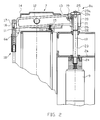
- the cantilever arm 13 is still pivotable via a horizontal pin 19 otherwise non-rotatably connected to a sleeve 20, which acts as a gear part or as a spindle gear trained pivot guide 8a of FIG. 2 is formed.
- the threaded sleeve 20 includes an internal thread 21 which is on an external thread 22 of a drive shaft 23, whose drive axis coincides with the pivot axis 10, axially is screwable.
- the drive shaft 23 is received in a bearing 24 and directly driven by motor 9.
- a stop disk 25 screwed on the underside of which forms a first friction surface 25a with which one second friction surface 20a formed on the top of the threaded sleeve 20 Engagement occurs when the threaded sleeve 20 has reached its highest point.
- a spring 26 is arranged between the carrier 7 and the threaded sleeve 20. The spring 26 loads the threaded sleeve 20 in the direction of the stop disk 25 during the component of the Movement path, and loaded the threaded sleeve 20 when pivoting the cover 7 in the closed position.
- Both functions can, for example, by a Helical compression spring are met, the ends of which on the threaded sleeve 20 and Carrier 7 are set so that the spring 26 after both axial movement is clamped below as well as in the pivoting movement in the closed position.
- the coffee machine with the pivoting guide 8a of FIG. 2 works as follows:
- the drive continues to run until the boom arm turns around pivoted the bolt 19 into a substantially parallel position to the sealing part 11 and the spring 15 has tensioned so that the sealing member 11 with a predetermined Pressure is pressed on the opening 6a, which is sufficient, the brewing pressure inside the Resist brewing cylinder 6.
- the drive 9 is stopped and locks the drive shaft 23 against rotation so that the cover 7 does not open unintentionally can.
- the drive is started in the opposite direction and moves the threaded sleeve 20, supported by the spring 26, upwards, whereby at the same time the peripheral tension of the spring 26 is increased and the pivoting process is introduced parallel to the plane of the opening 6a, so that the nose 16 from the counter bearing 17 is released.
- the drive 9 remains switched on until the threaded sleeve 20 again with their friction surface 20a in frictional engagement with the friction surface 25a of the stop disk 25 has reached and the cover 7 is again in the open position 1 has pivoted.
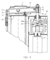
- FIG. 3 shows a further embodiment of an equipped according to the invention Coffee machine, which differ from the embodiment of FIG. 2 only by another Pivotal guide 8a differs. In relation to the other components, it can reference is made to the explanation of FIG. 2.
- the pivoting guide 8b contains a type of ratchet gear with a first gear element, which acts as a rotating sleeve 27 or rotating cage or the like. is formed.
- the rotating sleeve 27 is directly on the motor 9 to the Swivel axis 10 driven in rotation.
- the motor 9 facing away from the Pivot axis 10 through the end face of the rotary sleeve 27 is with a first Inclined surface 27a, which is designed in the manner of an inclined plane and extends transversely to the axis of rotation 10. At the highest point of the first inclined surface 27a is followed by a first stop surface 27b in the axial direction.
- a second gear element in the form of a disk 28 rotatable about the axis of rotation 10 and arranged to be displaceable in the axial direction.
- the disk 28 also has a corresponding to the first inclined surface 27a, second inclined surface 28a, which merges into an axial stop surface 28b.
- Both Sloping surfaces are corresponding, expediently under a self-locking Angle, inclined, and can rest on each other over the entire surface.
- the two too Stop surfaces 27b and 28b are essentially designed to correspond.
- the disk 28 is fixedly connected to a drive shaft 30 via a pin 29 Center line coincides with the axis of rotation 10.
- the drive shaft 30 extends the side opposite the drive 9 out of the rotating sleeve 27 and is in Carrier 2a rotatably and axially slidably mounted.
- the cover 7 At the top of the drive shaft 30 is the cover 7, for example via a bearing eye 31 and a wedge 32 connected to the drive shaft 30 that every axial and each rotational movement of the drive shaft 30 is transferred to the cover 7.
- the turntable 28 is supported in the interior of the rotating sleeve 27 by a spring 33, which takes up the weight of the cover 7 with the drive shaft 30 and the two Presses inclined surfaces 27a and 28a into engagement with one another.
- the coffee machine equipped with the swivel guide 8b works as follows:
- the gear elements can be arranged in mirror image, for example in the design 2, the threaded sleeve with the drive and the spindle with the cover or in the embodiment of FIG. 3, the rotary sleeve with the cover and Disk with the drive.
- Other configurations are conceivable.
- the function of the spring in Fig. 2 perceived by two separate Fedem become. Under certain circumstances, the spring can also be omitted entirely.
- the lid design is not limited to the described embodiment.
Landscapes
- Engineering & Computer Science (AREA)
- Food Science & Technology (AREA)
- Apparatus For Making Beverages (AREA)
Priority Applications (2)
| Application Number | Priority Date | Filing Date | Title |
|---|---|---|---|
| EP19990115423 EP1074209B1 (fr) | 1999-08-04 | 1999-08-04 | Machine à café |
| DE59907943T DE59907943D1 (de) | 1999-08-04 | 1999-08-04 | Kaffeemaschine |
Applications Claiming Priority (1)
| Application Number | Priority Date | Filing Date | Title |
|---|---|---|---|
| EP19990115423 EP1074209B1 (fr) | 1999-08-04 | 1999-08-04 | Machine à café |
Publications (2)
| Publication Number | Publication Date |
|---|---|
| EP1074209A1 true EP1074209A1 (fr) | 2001-02-07 |
| EP1074209B1 EP1074209B1 (fr) | 2003-12-03 |
Family
ID=8238728
Family Applications (1)
| Application Number | Title | Priority Date | Filing Date |
|---|---|---|---|
| EP19990115423 Expired - Lifetime EP1074209B1 (fr) | 1999-08-04 | 1999-08-04 | Machine à café |
Country Status (2)
| Country | Link |
|---|---|
| EP (1) | EP1074209B1 (fr) |
| DE (1) | DE59907943D1 (fr) |
Citations (3)
| Publication number | Priority date | Publication date | Assignee | Title |
|---|---|---|---|---|
| EP0528757A1 (fr) * | 1991-07-30 | 1993-02-24 | Sintra Holding Ag | Dispositif d'infusion pour une machine à café et méthode pour faire du café |
| US5492054A (en) * | 1993-08-11 | 1996-02-20 | Prodiana Ag | Coffee maker with a metering device |
| EP0864284A1 (fr) | 1997-03-13 | 1998-09-16 | Wmf Württembergische Metallwarenfabrik Ag | Machine à café |
-
1999
- 1999-08-04 EP EP19990115423 patent/EP1074209B1/fr not_active Expired - Lifetime
- 1999-08-04 DE DE59907943T patent/DE59907943D1/de not_active Expired - Fee Related
Patent Citations (3)
| Publication number | Priority date | Publication date | Assignee | Title |
|---|---|---|---|---|
| EP0528757A1 (fr) * | 1991-07-30 | 1993-02-24 | Sintra Holding Ag | Dispositif d'infusion pour une machine à café et méthode pour faire du café |
| US5492054A (en) * | 1993-08-11 | 1996-02-20 | Prodiana Ag | Coffee maker with a metering device |
| EP0864284A1 (fr) | 1997-03-13 | 1998-09-16 | Wmf Württembergische Metallwarenfabrik Ag | Machine à café |
Also Published As
| Publication number | Publication date |
|---|---|
| DE59907943D1 (de) | 2004-01-15 |
| EP1074209B1 (fr) | 2003-12-03 |
Similar Documents
| Publication | Publication Date | Title |
|---|---|---|
| EP2036466B1 (fr) | Dispositif-infuseur pour une machine à café | |
| DE19832063C2 (de) | Espressobrühkopfeinheit | |
| EP2105075B1 (fr) | Dispositif-infuseur pour une machine à café | |
| DE3333029A1 (de) | Spannfutter zum aufhaengen eines werkstueckhalters an einer senkrechten antriebswelle | |
| DE3307049A1 (de) | Vorrichtung zum verstellen eines gegenstandes | |
| CH708734A1 (de) | Modulare Brüheinheit für eine Kaffeemaschine. | |
| EP1595480B1 (fr) | Machine à café automatique | |
| EP1109983A1 (fr) | Charniere a visser comportant une position d'arret | |
| CH691221A5 (de) | Stichsäge. | |
| DE1125312B (de) | Rasierhobel | |
| EP1074209B1 (fr) | Machine à café | |
| DE3205491A1 (de) | Raffstore | |
| EP0512384B1 (fr) | Dispositif de palier pour arbres, en particulier pour arbres de serrage dans les machines à enrouler | |
| DE4428886C2 (de) | Armlehne für Kraftfahrzeugsitze mit einem Hohlraum zur Aufnahme eines Telefongerätes | |
| CH681955A5 (fr) | ||
| EP4608215A1 (fr) | Dispositif de fermeture pour récipient de matériau broyé, récipient de matériau broyé et machine à café comprenant un tel récipient de matériau broyé | |
| DE8618695U1 (de) | Befestigungseinrichtung für scheibenförmige Werkzeuge an der Werkzeugspindel einer tragbaren Elektrowerkzeugmaschine | |
| EP0864284B1 (fr) | Machine à café | |
| EP1143837B1 (fr) | Machine a cafe | |
| DE9403832U1 (de) | Gefäßfüllmaschine | |
| EP4209156A1 (fr) | Unité de broyage pour dispositif de préparation de boissons avec réglage amélioré du degré de broyage | |
| DE19522835A1 (de) | Angelrolle | |
| DE4011419C2 (de) | Umschalthebel für das Umschaltventil eines Mehrkammerfilters mit abwechselnd beaufschlagbaren Filterkammern | |
| DE3206292C2 (de) | Verriegelungsvorrichtung für einen abnehmbaren Sonnenschutz an einem Fahrzeugdach | |
| EP1502527B1 (fr) | Dispositif d'infusion avec un système de mouvement axial d'un élément taraudé |
Legal Events
| Date | Code | Title | Description |
|---|---|---|---|
| PUAI | Public reference made under article 153(3) epc to a published international application that has entered the european phase |
Free format text: ORIGINAL CODE: 0009012 |
|
| AK | Designated contracting states |
Kind code of ref document: A1 Designated state(s): DE |
|
| AX | Request for extension of the european patent |
Free format text: AL;LT;LV;MK;RO;SI |
|
| 17P | Request for examination filed |
Effective date: 20010807 |
|
| AKX | Designation fees paid |
Free format text: DE |
|
| GRAH | Despatch of communication of intention to grant a patent |
Free format text: ORIGINAL CODE: EPIDOS IGRA |
|
| GRAS | Grant fee paid |
Free format text: ORIGINAL CODE: EPIDOSNIGR3 |
|
| GRAA | (expected) grant |
Free format text: ORIGINAL CODE: 0009210 |
|
| AK | Designated contracting states |
Kind code of ref document: B1 Designated state(s): DE |
|
| REF | Corresponds to: |
Ref document number: 59907943 Country of ref document: DE Date of ref document: 20040115 Kind code of ref document: P |
|
| PLBE | No opposition filed within time limit |
Free format text: ORIGINAL CODE: 0009261 |
|
| STAA | Information on the status of an ep patent application or granted ep patent |
Free format text: STATUS: NO OPPOSITION FILED WITHIN TIME LIMIT |
|
| 26N | No opposition filed |
Effective date: 20040906 |
|
| PGFP | Annual fee paid to national office [announced via postgrant information from national office to epo] |
Ref country code: DE Payment date: 20071029 Year of fee payment: 9 |
|
| PG25 | Lapsed in a contracting state [announced via postgrant information from national office to epo] |
Ref country code: DE Free format text: LAPSE BECAUSE OF NON-PAYMENT OF DUE FEES Effective date: 20090303 |