EP1074221A2 - Angiographiegerät mit CO2 Injektion - Google Patents
Angiographiegerät mit CO2 Injektion Download PDFInfo
- Publication number
- EP1074221A2 EP1074221A2 EP00500169A EP00500169A EP1074221A2 EP 1074221 A2 EP1074221 A2 EP 1074221A2 EP 00500169 A EP00500169 A EP 00500169A EP 00500169 A EP00500169 A EP 00500169A EP 1074221 A2 EP1074221 A2 EP 1074221A2
- Authority
- EP
- European Patent Office
- Prior art keywords
- injection
- angiography
- metering device
- valves
- gas
- Prior art date
- Legal status (The legal status is an assumption and is not a legal conclusion. Google has not performed a legal analysis and makes no representation as to the accuracy of the status listed.)
- Granted
Links
Images


Classifications
-
- A—HUMAN NECESSITIES
- A61—MEDICAL OR VETERINARY SCIENCE; HYGIENE
- A61M—DEVICES FOR INTRODUCING MEDIA INTO, OR ONTO, THE BODY; DEVICES FOR TRANSDUCING BODY MEDIA OR FOR TAKING MEDIA FROM THE BODY; DEVICES FOR PRODUCING OR ENDING SLEEP OR STUPOR
- A61M5/00—Devices for bringing media into the body in a subcutaneous, intra-vascular or intramuscular way; Accessories therefor, e.g. filling or cleaning devices, arm-rests
- A61M5/14—Infusion devices, e.g. infusing by gravity; Blood infusion; Accessories therefor
- A61M5/142—Pressure infusion, e.g. using pumps
- A61M5/145—Pressure infusion, e.g. using pumps using pressurised reservoirs, e.g. pressurised by means of pistons
- A61M5/1452—Pressure infusion, e.g. using pumps using pressurised reservoirs, e.g. pressurised by means of pistons pressurised by means of pistons
- A61M5/1456—Pressure infusion, e.g. using pumps using pressurised reservoirs, e.g. pressurised by means of pistons pressurised by means of pistons with a replaceable reservoir comprising a piston rod to be moved into the reservoir, e.g. the piston rod is part of the removable reservoir
-
- A—HUMAN NECESSITIES
- A61—MEDICAL OR VETERINARY SCIENCE; HYGIENE
- A61B—DIAGNOSIS; SURGERY; IDENTIFICATION
- A61B6/00—Apparatus or devices for radiation diagnosis; Apparatus or devices for radiation diagnosis combined with radiation therapy equipment
- A61B6/48—Diagnostic techniques
- A61B6/481—Diagnostic techniques involving the use of contrast agents
-
- A—HUMAN NECESSITIES
- A61—MEDICAL OR VETERINARY SCIENCE; HYGIENE
- A61B—DIAGNOSIS; SURGERY; IDENTIFICATION
- A61B6/00—Apparatus or devices for radiation diagnosis; Apparatus or devices for radiation diagnosis combined with radiation therapy equipment
- A61B6/50—Apparatus or devices for radiation diagnosis; Apparatus or devices for radiation diagnosis combined with radiation therapy equipment specially adapted for specific body parts; specially adapted for specific clinical applications
- A61B6/504—Apparatus or devices for radiation diagnosis; Apparatus or devices for radiation diagnosis combined with radiation therapy equipment specially adapted for specific body parts; specially adapted for specific clinical applications for diagnosis of blood vessels, e.g. by angiography
-
- A—HUMAN NECESSITIES
- A61—MEDICAL OR VETERINARY SCIENCE; HYGIENE
- A61M—DEVICES FOR INTRODUCING MEDIA INTO, OR ONTO, THE BODY; DEVICES FOR TRANSDUCING BODY MEDIA OR FOR TAKING MEDIA FROM THE BODY; DEVICES FOR PRODUCING OR ENDING SLEEP OR STUPOR
- A61M5/00—Devices for bringing media into the body in a subcutaneous, intra-vascular or intramuscular way; Accessories therefor, e.g. filling or cleaning devices, arm-rests
- A61M5/007—Devices for bringing media into the body in a subcutaneous, intra-vascular or intramuscular way; Accessories therefor, e.g. filling or cleaning devices, arm-rests for contrast media
-
- A—HUMAN NECESSITIES
- A61—MEDICAL OR VETERINARY SCIENCE; HYGIENE
- A61M—DEVICES FOR INTRODUCING MEDIA INTO, OR ONTO, THE BODY; DEVICES FOR TRANSDUCING BODY MEDIA OR FOR TAKING MEDIA FROM THE BODY; DEVICES FOR PRODUCING OR ENDING SLEEP OR STUPOR
- A61M2202/00—Special media to be introduced, removed or treated
- A61M2202/02—Gases
- A61M2202/0225—Carbon oxides, e.g. Carbon dioxide
-
- A—HUMAN NECESSITIES
- A61—MEDICAL OR VETERINARY SCIENCE; HYGIENE
- A61M—DEVICES FOR INTRODUCING MEDIA INTO, OR ONTO, THE BODY; DEVICES FOR TRANSDUCING BODY MEDIA OR FOR TAKING MEDIA FROM THE BODY; DEVICES FOR PRODUCING OR ENDING SLEEP OR STUPOR
- A61M5/00—Devices for bringing media into the body in a subcutaneous, intra-vascular or intramuscular way; Accessories therefor, e.g. filling or cleaning devices, arm-rests
- A61M5/14—Infusion devices, e.g. infusing by gravity; Blood infusion; Accessories therefor
- A61M5/142—Pressure infusion, e.g. using pumps
- A61M5/145—Pressure infusion, e.g. using pumps using pressurised reservoirs, e.g. pressurised by means of pistons
- A61M5/1452—Pressure infusion, e.g. using pumps using pressurised reservoirs, e.g. pressurised by means of pistons pressurised by means of pistons
- A61M5/14546—Front-loading type injectors
Definitions
- the present invention is to provide an apparatus for angiography by the injection of CO 2 , which has substantial advantages over the prior art.
- angiography concerns methods of radiological diagnosis by the injection of a contrast medium in order to permit the assessment of vascular lesions, such as stenosis, occlusions, aneurysm, fistulas, etc.
- vascular lesions such as stenosis, occlusions, aneurysm, fistulas, etc.
- these procedures are carried out in vascular radiology rooms provided with the equipment necessary for carrying out the radiographic technique, normally with radiological systems which permit digital subtraction angiography, or DSA, under the best possible conditions.
- contrast media are based on iodine which is radio-opaque to X-rays.
- iodated contrast media can cause allergies, are nephrotoxic and, likewise, can produce cardiovascular complications.
- the CO 2 displaces the blood in the vessel and briefly creates a gas bubble which moves in the direction of blood flow.
- the digital subtraction angiography equipment takes a series of radiographic images in which the passage of the contrast medium through the vessel being studied is recorded. Afterwards, the best image recorded can be selected to be transferred to a physical support (radiography).
- the angiography apparatus to which the present invention relates has advantageous functional features compared with currently known apparatus, providing means that permit the autonomous injection of CO 2 into the blood vessel, having a large number of regulating and control means which enable the process to be carried out and monitored with safety features which have been unknown hitherto and also providing practical means which, in a simple and readily transportable manner, make it possible to have available all the elements for carrying out angiography by injection of CO 2 .
- the apparatus to which the present invention relates basically comprises a foot carrying the CO 2 source, and a column carrying, at its upper portion, the movable arm, which is of an articulated type, forming two regions in the second of which the receiving support for the CO 2 -metering device is installed.
- the movable arm unit is adjustable both in terms of rotation about an axis coinciding with the geometrical axis of the column and in terms of pivoting on the first member of the movable arm, which member is composed of an articulated parallelogram, and, likewise, on the second member of the movable arm, or the support for the metering device, which is also adjustable in terms of rotation with respect to the first arm member.
- the column accommodates a hand grip and a perfusion support of the type which can be adjusted in height.
- a screen which is rotatable about the geometrical axis of articulation of the two members forming the movable arm and which is also inclinable, enables the apparatus to be programmed and controlled.
- This arrangement permits both an efficient and compact arrangement of all the members making up the apparatus, and efficient control of all the functions thereof.
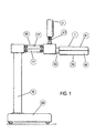
- Figure 1 is a side view of the apparatus.
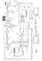
- Figure 2 shows schematically, in a block diagram, all of the members making up the apparatus.
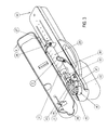
- Figure 3 is a perspective view of the second member of the movable arm in the open position.
- Figure 4 is a perspective view of the base of the second member of the movable arm carrying the CO 2 -metering device.
- Figure 5 is a perspective view of the end for operating the valves of the metering device.
- FIGs 6 and 7 are details of the end of the arm represented in Figure 5.
- Figure 8 is a perspective view of the unit made up of the CO 2 reservoir and the members for metering the CO 2 .
- the apparatus which has been generally indicated 1 has a base 64, provided with wheels, which contains the carbon dioxide reservoir and from which extends the support column 16 carrying an upper, movable arm composed of the two members 18 and 19 which are articulated to one another by an intermediate shaft 63.
- the first member 18 of the movable arm is in the form of an articulated parallelogram having two arms 17 and 17' enabling it to pivot with respect to the upright position of the shaft 63 for the rotation of the member 19 of the arm.
- the member 19 has two component parts, a lower body or base 60 and a cover 61, which are to enclose the metering device and to interact therewith.
- a screen 21 is arranged on the movable arm and has the ability to tilt and rotate about the articulation 41.
- the movable arm 18 is also rotatable about an upright axis, and therefore there is a vary wide range of possible adjustment positions for the end of the arm 19 and for the screen 21.
- a perfusion support (not shown) is coupled to the upper portion of the column 16 and its position can be adjusted by vertical displacement.
- the apparatus is in a form such that the gas supply passes from the base 64 to the metering unit accommodated inside the movable arm member 19, which is constituted by the base 60 and the cover 61, the unit being capable of being connected to a catheter for the introduction of carbon dioxide into the blood vessel being monitored in the patient.
- the screen 21 permits the programming and control of the angiographic process.
- the apparatus is basically described as a supplier of CO 2 for angiography, it could also work with any other appropriate gas, introducing it into the bloodstream of the patient in order to carry out the angiographic process.
- the dose of gas, and also the supply pressure, are controlled by the apparatus after the programming has been fixed by the apparatus with the desired reference values.
- the constitution of the apparatus provides for the catheter to be washed with a physiological solution while waiting for exploration to commence and also makes it possible to synchronise the supply of carbon dioxide with an X-ray apparatus.
- Metering is effected by a single-use metering device 2.
- the carbon dioxide passes from the source 3 to the metering device 2 which supplies it to the patient in a controlled manner.
- the gas from the source 3 flows through the connection piece 4 and a flexible tube 7, is purified by the 0.5- ⁇ m filter 5 and its pressure is set by the two-stage pressure regulator 6.
- the pressure switch 8 informs the control card 20 when the pressure of the source 3 is less than 10 bar, in which case the user is warned of the advisability of refilling it.
- a safety valve 9 inserted in the pressure regulator 6 releases the gas to the atmosphere when it exceeds the reference pressure of said valve.
- the carbon dioxide passes through the connection 10 and the duct 11 to the electrovalve 12, the closing and opening of which are brought about by the control card 20 in accordance with the stage of the process the apparatus has reached.
- the electrically operated valve 12 is opened by the control card 20, the carbon dioxide passing through a flow meter formed by the pressure sensor 13, the fixed-opening throttle 14 and the pressure sensor 15.
- the principle by which the meter operates is the difference in pressure produced between the ends of a throttle when gas passes through it, which difference in pressure is directly proportional to the flow of the gas.
- the duct 36, the luer-lock connection 37 and the duct 38 form the circuit through which the carbon dioxide flows from the outlet of the pressure sensor 15 to the 0.22 ⁇ m filter arranged in the inlet connection 40 of the metering device 2.
- the metering device 2 Before supplying the carbon dioxide to the patient, the metering device 2 has to be completely emptied of air because the introduction of air into the vascular system could cause a gas embolism. To that end, the apparatus 1 carries out several filling-emptying cycles on the metering device 2 so that any air in the circuits is released to the atmosphere. Once that operation has been completed, the metering device is ready to supply carbon dioxide to the patient.
- the procedure for emptying the metering device 2 is as follows: the motor 24 is controlled by the control card 20 and causes the member 46 and, because it is inserted therein, the valve 32 of the manifold 31, to rotate until the connection 40 is in communication with the pressure sensor 30.
- the control card 20 activates the motor 25 which, because it is connected to the screw 26 by means of the flexible coupling 53, brings about the rotation of said screw and, therefore, the displacement of the housing 27 and the plunger 28 of the syringe 29, which plunger is inserted in said housing.
- the movement stops when the plunger frees the volume of the syringe 29, for example 60 ml, and, while this situation continues, the carbon dioxide flows into it because it is at a positive pressure.
- the control card 20 maintains this situation for a predetermined period, allowing the gas time to fill all of the space which the plunger has freed, and, immediately afterwards, activates the motors 23 and 24 until the valves 33 and 32 are in a position such that the carbon dioxide is released to the atmosphere by way of the distal end 43 of the manifold 31, passing by way of the pressure sensor 30.
- the control card 20 acts on the motor 25 to cause it to move the plunger 28 until the syringe has been completely emptied, at which moment this movement stops and the valves 33 and 32 of the manifold 31 return to their closed position. The entire cycle is repeated three times.
- the user can select the supply of a physiological washing solution throughout the time during which intervention lasts, thus preventing the entry into the catheter of blood, which could form clots.
- the control card 20 acts on the motor 23 which, because it is fixed securely to the housing 46, displaces the valve 33 of the manifold 31, which valve 33 is inserted inside said housing, to its positions of perfusion, injection or closure, depending on the stage which the intervention has reached.
- the procedure for supplying carbon dioxide can start once the metering device has been drained, and can be repeated as many times as desired, provided that a waiting period is observed between consecutive injections, which can be programmed to be from 60 to 300 seconds, and that the total volume of gas supplied to the same patient does not exceed a value which can be programmed to be from 500 to 5000 ml.
- the supply process is started by the control card 20, once a check has been carried out to ensure that all of the safety conditions have been met.
- the first step of the sequence is to administer a small amount of carbon dioxide in order to empty the catheter of the physiological washing solution.
- the control card 20 causes the motor to bring about the rotation of the member 47 and, because it is inserted therein, the valve 32 of the manifold 31, until the connection 40 is in communication with the pressure sensor 30.
- the control card 20 activates the motor 25 which, being connected by way of the flexible coupling 53 to the screw 26, brings about the rotation of the latter and, therefore, the displacement of the housing 27 and the plunger 28 of the syringe 29, which plunger 28 is inserted in said housing.
- the carbon dioxide flows into the syringe 29 because it is at a positive pressure, and it stops when the plunger frees the volume of the syringe 29 which corresponds to the programmed dose of gas for washing the catheter, converted to the volume at the pressure read by the sensor 30, by applying the law of ideal gases.
- the control card 20 maintains this situation for a predetermined period, allowing the gas time to fill all of the space which the plunger has freed and, immediately afterwards, it activates the motor 24 until the valve 32 is in the closed position. It then causes the motor 25 to bring about the displacement of the plunger 28 of the syringe 29 until the pressure reader 30 indicates that the pressure programmed for the dose for washing the catheter has been reached.
- the control card 20 acts on the motors 23 and 24 to cause them to displace the valves 32 and 33 until they reach the open position, so that the carbon dioxide is released to the extension of the catheter 34 and, from there, to the patient's blood vessels.
- the control card 20 reads the pressure sensor 30 continuously, and acts accordingly on the motor 25 in order to keep the pressure constant, so that the washing of the catheter and the introduction of carbon dioxide into the patient's blood vessels are carried out in a uniform and controlled manner, avoiding compression and pressure peaks.
- the control card 20 returns the valves 32 and 33 to their closed position by acting on the motors 23 and 24.
- the control card 20 observes an absorption time programmed by the user before starting any other movement.
- the carbon dioxide has time to dissolve in the patient's blood and to be eliminated by respiration without impairing the quality of the images.
- the control card 20 starts another gas supply cycle like that described in the previous paragraph, but with the dose and the pressure programmed by the user.
- it generates an acoustic signal at a programmed time before carrying out the administration of the carbon dioxide, so that the user can generate the masking images for the subsequent processing of the images obtained. Otherwise, the cycle of introducing gas into the syringe, pressurising and supplying at a constant pressure is identical to the one already described.
- the apparatus 1 carries out exhaustive checks to ensure that the gas is being supplied correctly, and also to avoid any risk to the patient and user.
- the safety measures taken are the following:
Landscapes
- Health & Medical Sciences (AREA)
- Life Sciences & Earth Sciences (AREA)
- Engineering & Computer Science (AREA)
- Veterinary Medicine (AREA)
- Medical Informatics (AREA)
- Biomedical Technology (AREA)
- Heart & Thoracic Surgery (AREA)
- Animal Behavior & Ethology (AREA)
- General Health & Medical Sciences (AREA)
- Public Health (AREA)
- Vascular Medicine (AREA)
- Physics & Mathematics (AREA)
- Pathology (AREA)
- Surgery (AREA)
- Hematology (AREA)
- Biophysics (AREA)
- High Energy & Nuclear Physics (AREA)
- Anesthesiology (AREA)
- Nuclear Medicine, Radiotherapy & Molecular Imaging (AREA)
- Optics & Photonics (AREA)
- Molecular Biology (AREA)
- Radiology & Medical Imaging (AREA)
- Dentistry (AREA)
- Oral & Maxillofacial Surgery (AREA)
- Infusion, Injection, And Reservoir Apparatuses (AREA)
- Media Introduction/Drainage Providing Device (AREA)
- Apparatus For Radiation Diagnosis (AREA)
- Medicines Containing Antibodies Or Antigens For Use As Internal Diagnostic Agents (AREA)
- Medicines Containing Material From Animals Or Micro-Organisms (AREA)
Applications Claiming Priority (2)
| Application Number | Priority Date | Filing Date | Title |
|---|---|---|---|
| ES9901773 | 1999-08-04 | ||
| ES009901773A ES2162573B1 (es) | 1999-08-04 | 1999-08-04 | Aparato de angiografia por inyeccion de co2. |
Publications (3)
| Publication Number | Publication Date |
|---|---|
| EP1074221A2 true EP1074221A2 (de) | 2001-02-07 |
| EP1074221A3 EP1074221A3 (de) | 2001-10-24 |
| EP1074221B1 EP1074221B1 (de) | 2004-02-04 |
Family
ID=8309508
Family Applications (1)
| Application Number | Title | Priority Date | Filing Date |
|---|---|---|---|
| EP00500169A Expired - Lifetime EP1074221B1 (de) | 1999-08-04 | 2000-07-27 | Angiographiegerät mit CO2 Injektion |
Country Status (5)
| Country | Link |
|---|---|
| US (1) | US6503226B1 (de) |
| EP (1) | EP1074221B1 (de) |
| AT (1) | ATE258763T1 (de) |
| DE (1) | DE60008044T2 (de) |
| ES (2) | ES2162573B1 (de) |
Cited By (6)
| Publication number | Priority date | Publication date | Assignee | Title |
|---|---|---|---|---|
| FR2848859A1 (fr) * | 2002-12-20 | 2004-06-25 | Sedat | Dispositif de distribution pour un reseau d'acheminement de fluides medicaux vers un patient |
| WO2006044409A3 (en) * | 2004-10-13 | 2006-07-06 | Liebel Flarsheim Co | Power injection system with powerhead having a display |
| US7727196B2 (en) | 2004-10-13 | 2010-06-01 | Mallinckrodt Inc. | Powerhead of a power injection system |
| ES2372511A1 (es) * | 2011-12-02 | 2012-01-23 | Nicolas Anthony Costovici | Sistema para la inyección de fluidos de uso médico en el sistema vascular de un paciente. |
| WO2014012802A1 (en) * | 2012-07-20 | 2014-01-23 | Fresenius Vial Sas | Syringe pump with pivotable display |
| WO2019193032A1 (en) | 2018-04-03 | 2019-10-10 | Kinepict Health Ltd. | Contrast agent delivery system and method of delivering contrast agent to a patient, computer program and non-volatile data carrier |
Families Citing this family (22)
| Publication number | Priority date | Publication date | Assignee | Title |
|---|---|---|---|---|
| JP2008520287A (ja) | 2004-11-16 | 2008-06-19 | メドラッド インコーポレーテッド | 薬剤注入に対する患者搬送関数を決定し、患者反応をモデル化するシステム及び方法 |
| HUE034171T2 (en) | 2004-11-24 | 2018-02-28 | Bayer Healthcare Llc | Tools, systems and procedures for fluid transfer |
| ITPD20060126A1 (it) * | 2006-04-05 | 2007-10-06 | Omvl Srl | Dispositivo di controllo della erogazione di un gas combustibile in motori a combustione interna. |
| WO2008085421A2 (en) | 2006-12-29 | 2008-07-17 | Medrad, Inc. | Patient-based parameter generation systems for medical injection procedures |
| JP5437240B2 (ja) | 2007-07-17 | 2014-03-12 | メドラッド インコーポレーテッド | 心肺機能の評価、及び流体搬送の手順のパラメータを決定する装置、システム及び方法 |
| US9421330B2 (en) | 2008-11-03 | 2016-08-23 | Bayer Healthcare Llc | Mitigation of contrast-induced nephropathy |
| IT1398604B1 (it) * | 2009-11-23 | 2013-03-08 | Spark S R L | Dispositivo per il dosaggio e la regolazione del flusso di un mezzo di contrasto per l'esecuzione di angiografie |
| US20110301539A1 (en) * | 2010-06-08 | 2011-12-08 | Rickard Matthew J A | Fill and purge system for a drug reservoir |
| JP6025718B2 (ja) | 2010-06-24 | 2016-11-16 | ベイヤー メディカル ケア インク. | 注入プロトコルのための医薬品の伝播およびパラメータ生成のモデル |
| EP2850418B1 (de) | 2012-05-14 | 2019-02-20 | Bayer Healthcare LLC | Systeme und verfahren zur festlegung von protokollen über injektionen einer pharmazeutischen flüssigkeit auf basis einer röntgenröhrenspannung |
| US9555379B2 (en) | 2013-03-13 | 2017-01-31 | Bayer Healthcare Llc | Fluid path set with turbulent mixing chamber, backflow compensator |
| US10898638B2 (en) | 2016-03-03 | 2021-01-26 | Bayer Healthcare Llc | System and method for improved fluid delivery in multi-fluid injector systems |
| US12263326B2 (en) | 2016-11-14 | 2025-04-01 | Bayer Healthcare Llc | Methods and systems for verifying the contents of a syringe used for medical fluid delivery |
| CA3068739A1 (en) | 2017-08-31 | 2019-03-07 | Bayer Healthcare Llc | Fluid path impedance assessment for improving fluid delivery performance |
| EP3675931B1 (de) | 2017-08-31 | 2021-08-11 | Bayer Healthcare LLC | System und verfahren zur einspritzdruckkalibrierung |
| EP3675929B1 (de) | 2017-08-31 | 2026-05-13 | Bayer Healthcare LLC | Verfahren zur dynamischen druckregelung in einem fluidinjektorsystem |
| US11478581B2 (en) | 2017-08-31 | 2022-10-25 | Bayer Healthcare Llc | Fluid injector system volume compensation system and method |
| US11786652B2 (en) | 2017-08-31 | 2023-10-17 | Bayer Healthcare Llc | System and method for drive member position and fluid injector system mechanical calibration |
| CN116966369A (zh) | 2018-04-19 | 2023-10-31 | 拜耳医药保健有限公司 | 流体注入器中空气检测的系统和方法 |
| CA3111209A1 (en) | 2018-08-28 | 2020-03-05 | Bayer Healthcare Llc | Fluid injector system with improved ratio performance |
| CN112823031B (zh) | 2018-08-28 | 2023-08-15 | 拜耳医药保健有限责任公司 | 防止流体回流的流体注入器系统、方法和计算机程序产品 |
| CN112842607B (zh) * | 2021-01-26 | 2022-10-14 | 青岛科技大学 | 一种人机交互式家畜用无针注射器 |
Family Cites Families (14)
| Publication number | Priority date | Publication date | Assignee | Title |
|---|---|---|---|---|
| US5249579A (en) * | 1990-03-09 | 1993-10-05 | E-Z-Em, Inc. | Contrast media injector |
| DE9216558U1 (de) * | 1992-12-04 | 1994-03-31 | Kloess, Wolfgang, 2400 Lübeck | Gasinjektor |
| DE69432582T2 (de) * | 1993-10-28 | 2003-11-27 | Medrad, Inc. | System zur Administration von Flüssigkeiten bei mehreren Patienten |
| CA2129284C (en) * | 1993-11-24 | 1999-03-09 | Kenneth J. Niehoff | Controlling plunger drives for fluid injection in animals |
| US6221045B1 (en) * | 1995-04-20 | 2001-04-24 | Acist Medical Systems, Inc. | Angiographic injector system with automatic high/low pressure switching |
| US5779675A (en) * | 1995-08-25 | 1998-07-14 | Medrad, Inc. | Front load pressure jacket system with syringe holder |
| IE77523B1 (en) * | 1995-09-11 | 1997-12-17 | Elan Med Tech | Medicament delivery device |
| US5807334A (en) * | 1995-10-20 | 1998-09-15 | Hodosh; Milton | Fluid dispensing apparatus |
| US6030368A (en) * | 1996-09-20 | 2000-02-29 | Azam Anwar | Power syringe having a base and a lever |
| US6042565A (en) * | 1996-10-18 | 2000-03-28 | Medrad, Inc. | Syringe, injector and injector system |
| US6315762B1 (en) * | 1996-11-14 | 2001-11-13 | Angiodynamics, Inc. | Contrast medium delivery system and associated method |
| US5868710A (en) * | 1996-11-22 | 1999-02-09 | Liebel Flarsheim Company | Medical fluid injector |
| US5913844A (en) * | 1997-06-17 | 1999-06-22 | Liebel-Flarsheim Company | Power injector and method providing removal of used disposable syringe |
| US5947929A (en) * | 1997-08-22 | 1999-09-07 | Coeur Laboratories, Inc. | Front-load angiographic injector system, angiographic syringe and plunger for angiographic syringe |
-
1999
- 1999-08-04 ES ES009901773A patent/ES2162573B1/es not_active Expired - Fee Related
-
2000
- 2000-07-18 US US09/618,712 patent/US6503226B1/en not_active Expired - Lifetime
- 2000-07-27 AT AT00500169T patent/ATE258763T1/de not_active IP Right Cessation
- 2000-07-27 DE DE60008044T patent/DE60008044T2/de not_active Expired - Lifetime
- 2000-07-27 ES ES00500169T patent/ES2211491T3/es not_active Expired - Lifetime
- 2000-07-27 EP EP00500169A patent/EP1074221B1/de not_active Expired - Lifetime
Cited By (15)
| Publication number | Priority date | Publication date | Assignee | Title |
|---|---|---|---|---|
| US7704236B2 (en) | 2002-12-20 | 2010-04-27 | Sedat | Distribution device for a supply network for supply of medical fluids to a patient |
| WO2004058331A1 (fr) * | 2002-12-20 | 2004-07-15 | Sedat | Dispositif de distribution pour un reseau d’acheminement de fluides medicaux vers un patient |
| FR2848859A1 (fr) * | 2002-12-20 | 2004-06-25 | Sedat | Dispositif de distribution pour un reseau d'acheminement de fluides medicaux vers un patient |
| CN100413548C (zh) * | 2002-12-20 | 2008-08-27 | Sedat公司 | 向病人供应药液的供应网络所用的分配装置 |
| US8366670B2 (en) | 2004-10-13 | 2013-02-05 | Mallinckrodt Llc | Powerhead of a power injection system |
| US7727196B2 (en) | 2004-10-13 | 2010-06-01 | Mallinckrodt Inc. | Powerhead of a power injection system |
| US8180434B2 (en) | 2004-10-13 | 2012-05-15 | Mallinckrodt Llc | Powerhead of a power injection system |
| US8282595B2 (en) | 2004-10-13 | 2012-10-09 | Mallinckrodt Llc | Powerhead of a power injection system |
| WO2006044409A3 (en) * | 2004-10-13 | 2006-07-06 | Liebel Flarsheim Co | Power injection system with powerhead having a display |
| ES2372511A1 (es) * | 2011-12-02 | 2012-01-23 | Nicolas Anthony Costovici | Sistema para la inyección de fluidos de uso médico en el sistema vascular de un paciente. |
| WO2013079743A1 (es) * | 2011-12-02 | 2013-06-06 | Costovici Nicolas Anthony | Sistema para la inyección de fluidos de uso médico en el sistema vascular de un paciente |
| EP2786773A4 (de) * | 2011-12-02 | 2015-12-23 | Nicolas Anthony Costovici | Fluidinjektionssystem zur medizinischen verwendung im gefässsystem eines patienten |
| WO2014012802A1 (en) * | 2012-07-20 | 2014-01-23 | Fresenius Vial Sas | Syringe pump with pivotable display |
| CN104582754A (zh) * | 2012-07-20 | 2015-04-29 | 费森尤斯维尔公司 | 具有可枢转的显示器的注射泵 |
| WO2019193032A1 (en) | 2018-04-03 | 2019-10-10 | Kinepict Health Ltd. | Contrast agent delivery system and method of delivering contrast agent to a patient, computer program and non-volatile data carrier |
Also Published As
| Publication number | Publication date |
|---|---|
| ES2211491T3 (es) | 2004-07-16 |
| EP1074221B1 (de) | 2004-02-04 |
| DE60008044T2 (de) | 2004-09-16 |
| ES2162573A1 (es) | 2001-12-16 |
| DE60008044D1 (de) | 2004-03-11 |
| ATE258763T1 (de) | 2004-02-15 |
| EP1074221A3 (de) | 2001-10-24 |
| ES2162573B1 (es) | 2002-08-01 |
| US6503226B1 (en) | 2003-01-07 |
Similar Documents
| Publication | Publication Date | Title |
|---|---|---|
| EP1074221B1 (de) | Angiographiegerät mit CO2 Injektion | |
| JP4119479B2 (ja) | 自動空気除去機能付き血液造影剤注入器 | |
| US8192397B2 (en) | Medical fluid injection and inflation system | |
| US7935074B2 (en) | Cassette system for peritoneal dialysis machine | |
| JP5442600B2 (ja) | 外部器具が治療装置に正確に接続されていることを検査するための検査方法および装置 | |
| EP1380261B1 (de) | Injektor für Röntgenkontrastmittel | |
| US5573515A (en) | Self purging angiographic injector | |
| US5249579A (en) | Contrast media injector | |
| JP6431011B2 (ja) | 多流体医療用注入器システムおよび操作方法 | |
| US8082018B2 (en) | System and method for multiple injection procedures on heart vessels | |
| JP4270748B2 (ja) | 多数プロセッサの冗長性を備える血管造影用注射器装置 | |
| US7662124B2 (en) | System and method for multiple injection procedures on heart vessels | |
| US5840026A (en) | Patient specific dosing contrast delivery systems and methods | |
| US20030028145A1 (en) | Angiographic injector system with multiple processor redundancy | |
| CA2599271A1 (en) | Portable apparatus for peritoneal dialysis therapy | |
| JP2001520905A (ja) | 自動的な高/低圧切換え機能を備える血管造影用注射装置 | |
| EP2504046B1 (de) | Vorrichtung zur dosierung und anpassung des flusses eines röntgendichten mittels zur durchführung einer angiografie | |
| JPS6053155A (ja) | 自動復膜潅流装置 |
Legal Events
| Date | Code | Title | Description |
|---|---|---|---|
| PUAI | Public reference made under article 153(3) epc to a published international application that has entered the european phase |
Free format text: ORIGINAL CODE: 0009012 |
|
| AK | Designated contracting states |
Kind code of ref document: A2 Designated state(s): AT BE CH CY DE DK ES FI FR GB GR IE IT LI LU MC NL PT SE |
|
| AX | Request for extension of the european patent |
Free format text: AL;LT;LV;MK;RO;SI |
|
| PUAL | Search report despatched |
Free format text: ORIGINAL CODE: 0009013 |
|
| AK | Designated contracting states |
Kind code of ref document: A3 Designated state(s): AT BE CH CY DE DK ES FI FR GB GR IE IT LI LU MC NL PT SE |
|
| AX | Request for extension of the european patent |
Free format text: AL;LT;LV;MK;RO;SI |
|
| RIC1 | Information provided on ipc code assigned before grant |
Free format text: 7A 61B 6/00 A, 7A 61M 5/145 B, 7A 61M 5/00 B |
|
| 17P | Request for examination filed |
Effective date: 20011008 |
|
| RAP1 | Party data changed (applicant data changed or rights of an application transferred) |
Owner name: PROBITAS PHARMA, S.A. |
|
| AKX | Designation fees paid |
Free format text: AT BE CH CY DE DK ES FI FR GB GR IE IT LI LU MC NL PT SE |
|
| GRAP | Despatch of communication of intention to grant a patent |
Free format text: ORIGINAL CODE: EPIDOSNIGR1 |
|
| GRAS | Grant fee paid |
Free format text: ORIGINAL CODE: EPIDOSNIGR3 |
|
| GRAA | (expected) grant |
Free format text: ORIGINAL CODE: 0009210 |
|
| AK | Designated contracting states |
Kind code of ref document: B1 Designated state(s): AT BE CH CY DE DK ES FI FR GB GR IE IT LI LU MC NL PT SE |
|
| PG25 | Lapsed in a contracting state [announced via postgrant information from national office to epo] |
Ref country code: AT Free format text: LAPSE BECAUSE OF FAILURE TO SUBMIT A TRANSLATION OF THE DESCRIPTION OR TO PAY THE FEE WITHIN THE PRESCRIBED TIME-LIMIT Effective date: 20040204 Ref country code: NL Free format text: LAPSE BECAUSE OF FAILURE TO SUBMIT A TRANSLATION OF THE DESCRIPTION OR TO PAY THE FEE WITHIN THE PRESCRIBED TIME-LIMIT Effective date: 20040204 Ref country code: LI Free format text: LAPSE BECAUSE OF FAILURE TO SUBMIT A TRANSLATION OF THE DESCRIPTION OR TO PAY THE FEE WITHIN THE PRESCRIBED TIME-LIMIT Effective date: 20040204 Ref country code: CH Free format text: LAPSE BECAUSE OF FAILURE TO SUBMIT A TRANSLATION OF THE DESCRIPTION OR TO PAY THE FEE WITHIN THE PRESCRIBED TIME-LIMIT Effective date: 20040204 Ref country code: FI Free format text: LAPSE BECAUSE OF FAILURE TO SUBMIT A TRANSLATION OF THE DESCRIPTION OR TO PAY THE FEE WITHIN THE PRESCRIBED TIME-LIMIT Effective date: 20040204 Ref country code: CY Free format text: LAPSE BECAUSE OF FAILURE TO SUBMIT A TRANSLATION OF THE DESCRIPTION OR TO PAY THE FEE WITHIN THE PRESCRIBED TIME-LIMIT Effective date: 20040204 Ref country code: BE Free format text: LAPSE BECAUSE OF FAILURE TO SUBMIT A TRANSLATION OF THE DESCRIPTION OR TO PAY THE FEE WITHIN THE PRESCRIBED TIME-LIMIT Effective date: 20040204 |
|
| REG | Reference to a national code |
Ref country code: GB Ref legal event code: FG4D |
|
| REG | Reference to a national code |
Ref country code: CH Ref legal event code: EP |
|
| REG | Reference to a national code |
Ref country code: IE Ref legal event code: FG4D |
|
| REF | Corresponds to: |
Ref document number: 60008044 Country of ref document: DE Date of ref document: 20040311 Kind code of ref document: P |
|
| PG25 | Lapsed in a contracting state [announced via postgrant information from national office to epo] |
Ref country code: GR Free format text: LAPSE BECAUSE OF FAILURE TO SUBMIT A TRANSLATION OF THE DESCRIPTION OR TO PAY THE FEE WITHIN THE PRESCRIBED TIME-LIMIT Effective date: 20040504 Ref country code: SE Free format text: LAPSE BECAUSE OF FAILURE TO SUBMIT A TRANSLATION OF THE DESCRIPTION OR TO PAY THE FEE WITHIN THE PRESCRIBED TIME-LIMIT Effective date: 20040504 Ref country code: DK Free format text: LAPSE BECAUSE OF FAILURE TO SUBMIT A TRANSLATION OF THE DESCRIPTION OR TO PAY THE FEE WITHIN THE PRESCRIBED TIME-LIMIT Effective date: 20040504 |
|
| REG | Reference to a national code |
Ref country code: ES Ref legal event code: FG2A Ref document number: 2211491 Country of ref document: ES Kind code of ref document: T3 |
|
| PG25 | Lapsed in a contracting state [announced via postgrant information from national office to epo] |
Ref country code: IE Free format text: LAPSE BECAUSE OF NON-PAYMENT OF DUE FEES Effective date: 20040727 Ref country code: LU Free format text: LAPSE BECAUSE OF NON-PAYMENT OF DUE FEES Effective date: 20040727 |
|
| PG25 | Lapsed in a contracting state [announced via postgrant information from national office to epo] |
Ref country code: MC Free format text: LAPSE BECAUSE OF NON-PAYMENT OF DUE FEES Effective date: 20040731 |
|
| NLV1 | Nl: lapsed or annulled due to failure to fulfill the requirements of art. 29p and 29m of the patents act | ||
| REG | Reference to a national code |
Ref country code: CH Ref legal event code: PL |
|
| ET | Fr: translation filed | ||
| PLBE | No opposition filed within time limit |
Free format text: ORIGINAL CODE: 0009261 |
|
| STAA | Information on the status of an ep patent application or granted ep patent |
Free format text: STATUS: NO OPPOSITION FILED WITHIN TIME LIMIT |
|
| 26N | No opposition filed |
Effective date: 20041105 |
|
| REG | Reference to a national code |
Ref country code: IE Ref legal event code: MM4A |
|
| REG | Reference to a national code |
Ref country code: FR Ref legal event code: CD |
|
| PG25 | Lapsed in a contracting state [announced via postgrant information from national office to epo] |
Ref country code: PT Free format text: LAPSE BECAUSE OF NON-PAYMENT OF DUE FEES Effective date: 20040704 |
|
| REG | Reference to a national code |
Ref country code: FR Ref legal event code: CA |
|
| REG | Reference to a national code |
Ref country code: FR Ref legal event code: PLFP Year of fee payment: 16 |
|
| REG | Reference to a national code |
Ref country code: FR Ref legal event code: PLFP Year of fee payment: 17 |
|
| PGFP | Annual fee paid to national office [announced via postgrant information from national office to epo] |
Ref country code: ES Payment date: 20160506 Year of fee payment: 17 Ref country code: GB Payment date: 20160603 Year of fee payment: 17 |
|
| PGFP | Annual fee paid to national office [announced via postgrant information from national office to epo] |
Ref country code: FR Payment date: 20160627 Year of fee payment: 17 Ref country code: IT Payment date: 20160606 Year of fee payment: 17 |
|
| PGFP | Annual fee paid to national office [announced via postgrant information from national office to epo] |
Ref country code: DE Payment date: 20160603 Year of fee payment: 17 |
|
| REG | Reference to a national code |
Ref country code: DE Ref legal event code: R082 Ref document number: 60008044 Country of ref document: DE Representative=s name: KLUNKER IP PATENTANWAELTE PARTG MBB, DE |
|
| REG | Reference to a national code |
Ref country code: DE Ref legal event code: R119 Ref document number: 60008044 Country of ref document: DE |
|
| GBPC | Gb: european patent ceased through non-payment of renewal fee |
Effective date: 20170727 |
|
| REG | Reference to a national code |
Ref country code: FR Ref legal event code: ST Effective date: 20180330 |
|
| PG25 | Lapsed in a contracting state [announced via postgrant information from national office to epo] |
Ref country code: GB Free format text: LAPSE BECAUSE OF NON-PAYMENT OF DUE FEES Effective date: 20170727 Ref country code: DE Free format text: LAPSE BECAUSE OF NON-PAYMENT OF DUE FEES Effective date: 20180201 |
|
| PG25 | Lapsed in a contracting state [announced via postgrant information from national office to epo] |
Ref country code: FR Free format text: LAPSE BECAUSE OF NON-PAYMENT OF DUE FEES Effective date: 20170731 |
|
| PG25 | Lapsed in a contracting state [announced via postgrant information from national office to epo] |
Ref country code: IT Free format text: LAPSE BECAUSE OF NON-PAYMENT OF DUE FEES Effective date: 20170727 |
|
| REG | Reference to a national code |
Ref country code: ES Ref legal event code: FD2A Effective date: 20181029 |
|
| PG25 | Lapsed in a contracting state [announced via postgrant information from national office to epo] |
Ref country code: ES Free format text: LAPSE BECAUSE OF NON-PAYMENT OF DUE FEES Effective date: 20170728 |