EP1074319A2 - Vorrichtung zum Pressen einer Metallplatte in einer bevorzügten Form - Google Patents
Vorrichtung zum Pressen einer Metallplatte in einer bevorzügten Form Download PDFInfo
- Publication number
- EP1074319A2 EP1074319A2 EP20000116173 EP00116173A EP1074319A2 EP 1074319 A2 EP1074319 A2 EP 1074319A2 EP 20000116173 EP20000116173 EP 20000116173 EP 00116173 A EP00116173 A EP 00116173A EP 1074319 A2 EP1074319 A2 EP 1074319A2
- Authority
- EP
- European Patent Office
- Prior art keywords
- rotary die
- metal plate
- pressing
- die
- shaping
- Prior art date
- Legal status (The legal status is an assumption and is not a legal conclusion. Google has not performed a legal analysis and makes no representation as to the accuracy of the status listed.)
- Granted
Links
- 239000002184 metal Substances 0.000 title claims abstract description 48
- 238000007493 shaping process Methods 0.000 claims abstract description 70
- 238000003754 machining Methods 0.000 description 7
- 238000012423 maintenance Methods 0.000 description 3
- 238000004519 manufacturing process Methods 0.000 description 2
Images


Classifications
-
- B—PERFORMING OPERATIONS; TRANSPORTING
- B21—MECHANICAL METAL-WORKING WITHOUT ESSENTIALLY REMOVING MATERIAL; PUNCHING METAL
- B21D—WORKING OR PROCESSING OF SHEET METAL OR METAL TUBES, RODS OR PROFILES WITHOUT ESSENTIALLY REMOVING MATERIAL; PUNCHING METAL
- B21D22/00—Shaping without cutting, by stamping, spinning, or deep-drawing
- B21D22/02—Stamping using rigid devices or tools
-
- B—PERFORMING OPERATIONS; TRANSPORTING
- B21—MECHANICAL METAL-WORKING WITHOUT ESSENTIALLY REMOVING MATERIAL; PUNCHING METAL
- B21D—WORKING OR PROCESSING OF SHEET METAL OR METAL TUBES, RODS OR PROFILES WITHOUT ESSENTIALLY REMOVING MATERIAL; PUNCHING METAL
- B21D5/00—Bending sheet metal along straight lines, e.g. to form simple curves
- B21D5/01—Bending sheet metal along straight lines, e.g. to form simple curves between rams and anvils or abutments
-
- B—PERFORMING OPERATIONS; TRANSPORTING
- B21—MECHANICAL METAL-WORKING WITHOUT ESSENTIALLY REMOVING MATERIAL; PUNCHING METAL
- B21D—WORKING OR PROCESSING OF SHEET METAL OR METAL TUBES, RODS OR PROFILES WITHOUT ESSENTIALLY REMOVING MATERIAL; PUNCHING METAL
- B21D19/00—Flanging or other edge treatment, e.g. of tubes
- B21D19/08—Flanging or other edge treatment, e.g. of tubes by single or successive action of pressing tools, e.g. vice jaws
- B21D19/082—Flanging or other edge treatment, e.g. of tubes by single or successive action of pressing tools, e.g. vice jaws for making negative angles
- B21D19/086—Flanging or other edge treatment, e.g. of tubes by single or successive action of pressing tools, e.g. vice jaws for making negative angles with rotary cams
Definitions
- the present invention relates to an apparatus for pressing a metal plate into a desired shape, particularly a curved shape, such as fenders or pillars for cars.
- a conventional apparatus for pressing and shaping a metal plate comprises a lower die “ a “ and an upper die “ f “.
- the lower die “ a” has a cavity “ b “ in which a rotary die “ c “ is rotatably supported, and the rotary die has a press-shaping section " d “ formed thereon.
- the upper die “ f " has a counter press-shaping blade " e “ formed to engage with the press-shaping section " d " with the metal plate sandwiched therebetween when the metal plate is pressed and shaped.
- the cavity “ b " of the lower die “ a” has receiving surfaces " g " formed thereon while the rotary die “ c “ has abutment surfaces " h “ formed thereon to abut on the receiving surfaces " g ".
- the upper and lower dies " f “ and “ a “ abut on each other with the abutment surfaces " h “ of the rotary die “ c “ abutting on the receiving surfaces " g " of the lower die “ a " (see Japanese Patent 8-276218A).
- the rotary die “ c” After pressing and shaping the metal plate, the rotary die “ c " is rotated to retract from the pressed-and-shaped metal plate so as to facilitate release and removal of the pressed-and-shaped plate from the mold assembly.
- the rotary die “ c” is of a cylindrical or round rod shape whereas the cavity “ b " is a round hole.
- New pressing-and-shaping apparatus must be designed and made every time cars are redesigned.
- the lower die of the conventional pressing-and-shaping apparatus uses a round rotary die fitting in its round-concave die the lower die has the round cavity and the rotary die is rotated in the round cavity, and such lower die requires inevitably extra dead spaces around the cavity, thus making it difficult to reduce the size of the pressing-and-shaping apparatus.
- one object of the present invention is to provide a pressing-and-shaping apparatus which is small in size, still being capable of shaping metal plates easily, smoothly and at reduced cost, requiring an easy maintenance with a minimum fee.
- an apparatus for pressing a metal plate into a desired shape comprising: a lower die having a cavity in which a rotary die is rotatable on an axis thereof; the rotary die having the rotational or pivotal axis extending in a longitudinal direction of the mold piece and having a press-shaping section formed to extend in the longitudinal direction; and an upper die having a counter press-shaping section formed to engage with the press-shaping section of the rotary die with the metal plate sandwiched therebetween at a time of pressing and shaping the metal plate, the cavity of the lower die having receiving sections for supporting the rotary die at the time of pressing and shaping the metal plate, each receiving section having flat receiving surface whereas the rotary die having abutment surfaces formed on its bottom to abut on the flat receiving surfaces, the rotary die being adapted to be set in a predetermined angular position at the time of pressing and shaping the metal plate and to rotate and return to a rest position after finishing the pressing and shaping of the metal plate, is improved according to
- the receiving sections and the abutment surfaces can desirably be determined in number, size and positions in consideration of the weight and size of the rotary die.
- the receiving section may be formed by carving the lower die at the time of forming the cavity in the lower die.
- it is preferable to form the receiving section with flat plate since use of the flat plate facilitates forming of the receiving section. It can be achieved only by bolting the flat plates to the lower die at desired positions in the cavity.
- the flat plates can be used as either or both of the first and second receiving portions. Furthermore, it is advantageous that worn plates can be changed readily for new flat plates.
- the abutment surfaces may be formed with flat plates bolted to an outer side of the rotary die.
- Use of the flat plates as abutment surfaces facilitates forming of the abutment surface, since it can be achieved only by bolting the flat plates to the rotary die at desired positions in outer surfaces. Furthermore, it is advantageous that worn plates can be changed readily for new flat plates.
- the flat plates can be used as either or both of the first and second abutment surface of the rotary die.
- the rotary die may include a circular arc surface formed on the central bottom, the circular arc being a part of the circle drawn about the pivot the rotary die turns, and the lower die may have a bearing mechanism for bearing the circular arc surface of the rotary die. This arrangement assures that the rotary die turns smoothly even if formed so long, still preventing the undesired sinking of the heavy rotary die.
- the bearing mechanism may include a pair of parallel rolls laterally arranged, on which the circular arc surface of the rotary die is rotatably supported. This provides a simple bearing structure, which is able to effectively prevent the undesired sinking of the heavy rotary die.
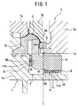
- an apparatus for pressing a metal plate into a desired shape includes a lower die 1 having a cavity 2 in which a rotary die 4 is rotatably supported.
- the lower die 1 comprises a concave body 1a and a forming piece 1b integrally connected to the top of the concave body 1a.
- a metal plate 3 to be pressed and shaped is put on the forming piece 1b.
- a cavity 2 of the concave body 1a takes an L-shape in cross section as seen in Figs. 1 and 2.
- the rotary die 4 is rotatable about its lateral axis P , and can be driven to a predetermined angular pressing and shaping position, and can be rotated and withdrawn to the rest position after finishing the pressing and shaping of the metal plate 3.
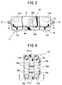
- the rotary die 4 takes an L-shape in cross section, and has a press-shaping section 4a formed on its upper, inner end for pressing and shaping a selected part of the metal plate 3. As shown in Fig.3, the L-shaped rotary die 4 extends in the longitudinal direction and has opposite ends supported by bearings 5.
- An upper die 7 includes a slide cam 7a capable of sliding laterally, and the slide cam 7a has a counter press-shaping section 6 formed thereon.
- the counter press-shaping section 6 is adapted to abut on the press-shaping section 4a of the lower die 4 with the metal plate 3 sandwiched therebetween when the metal plate 3 is pressed and shaped.
- the upper die 7 includes a pressing piece 7b and a flange shaping piece 7c, which can be moved back and forth relative to each other with associated cam means.
- a plurality of first and second receiving sections 8a and 8b are provided in the cavity 2 for supporting the rotary die 4 at the time of pressing and shaping the metal plate 3, which are arranged laterally on a predetermined position in the longitudinal direction.
- Each of the first receiving sections 8a includes a flat receiving surface to confront extending horizontally, i.e. in the direction in which the counter press-shaping section 6 moves (indicated by an arrow in Fig.1).
- Each of the second receiving sections 8b has a flat receiving surface extending vertically, i.e. in the direction perpendicular to the moving direction of the counter press-shaping section 6.
- the first receiving sections 8a are provided by fixing flat plates 9 to the lower die 1 at the horizontal concave surface with bolts 10 whereas the second receiving sections 8b are provided by machining the L-shaped lower die 1 at the vertical concave side to form plateau-like projections.
- the L-shaped rotary die 4 has a plurality of first abutment surfaces 11a and second abutment surfaces 11b arranged on horizontal and vertical sides thereof to abut on the first and second receiving sections 8a and 8b, respectively, upon pressing and shaping the metal plate 3.
- Each of the first abutment surfaces 11a is formed extending horizontally, i.e. in the moving direction of the counter press-shaping section 6.
- Each of the second abutment surfaces 11b is formed extending vertically, i.e. in the direction perpendicular to the moving direction.
- the first abutment surfaces 11a are formed by machining the L-shaped rotary die 4 at a horizontal outer side thereof to form plateau-like projections arranged in the longitudinal direction whereas the second abutment surfaces 11b are formed by fixing flat plates 9 to the rotary die 4 at the vertical outer side thereof with bolts 10.
- the first abutment surface 11a is arranged so that the front side 12 is positioned behind a vertical line L passing through the pivotal axis P of the rotary die 4.
- the second abutment surface 11b is arranged so that the upper side 13 thereof is positioned below a horizontal line H passing through the axis P .
- the L-shaped lower die 1 has a bearing mechanism 14 for supporting or receiving the rotary die 4 at the central bottom portion 4b thereof.
- the intermediate bearing section 4b of the bottom of the rotary die 4 includes a circular arc surface formed on the bottom of the L-shaped rotary die.
- the circular arc is a part of the circle drawn about the pivot P about which the rotary die 4 turns, and the bearing mechanism bears the circular arc surface of the rotary die 4 .
- the intermediate bearing section 4b of the bottom of the rotary die 4 is provided by fixing a circular arc plate 15 to the rotary die 4 with headed bolts 16, each having a hexagonal hole made in its head.
- the circular arc plate 15 is high-frequency hardened.
- the bearing mechanism 14 includes a pair of parallel rolls 14a laterally arranged, on which the circular arc surface 4b of the rotary die 4 is rotatably supported. Each roll 14a rotates about its lateral axis 14a 1 , and a holder 14b holds these lateral axes rotatably.
- the holder 14b is fixed to the lower die 1 with headed bolts 14d, each having a hexagonal hole made in its head, as seen from Fig.7.
- Each lateral axis 14a 1 is fixed in position with an associated pin 14e.
- a sheet of metal 3 to be pressed and shaped into a desired shape is put on the forming piece 1b of the lower die 1.
- the upper die 7 descends so that the slide cam 7a allows the rotary die 4 to pivot clockwise on the axis P so as to set the rotary die 4 at a predetermined working position, as shown in Fig.1.
- the pressing piece 7b moves down to fix the metal plate 3 onto the forming piece 1b of the lower die 1, while the flange shaping piece 7c moves down in pressing position, whereby determined portions of the metal plate 3 is shaped with the shaping pieces 7b and 7c.
- the slide cam 7a is moved along with the counter press-shaping section 6 in the direction as indicated by the arrow in Fig.1 to the metal plate 3 against the press-shaping section 4a of the rotary die 4, thereby shaping the pushed portion of the metal plate 3.
- the flat abutment surfaces 11a and 11b of the rotary die 4 are in contact with the flat receiving surfaces of the receiving sections 8a and 8b of the lower die 1, so that the die 1 bears the load of pressure which is applied to the rotary die 4.
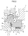
- the upper die 7 When the pressing-and-shaping work has been finished, the upper die 7 returns to its rest position, thus allowing the counter press-shaping section 6 of the slide cam 7a, the pressing piece 7b and the flange shaping piece 7c to leave the lower die 1.
- the returning of the upper die 7 to its rest position is detected by means of an associated sensor which generates a signal of returning.
- Piston-and-cylinder drive means responds to the signal from the sensor in order to rotate and move the rotary die 4 backward, as shown in Fig.2.
- the rotary die 4 is inclined so that the abutment surfaces 11a and 11b of the rotary die 4 may leave the receiving sections 8a and 8b of the lower die 1, and so that the press-shaping section 4a of the rotary die 4 may leave the pressed-and-shaped metal plate 3, whereby the finished metal plate 3 can readily be removed from the mold assembly.
- the lower die and the rotary die are so shaped that their cross sections may take an L-shape, and the horizontal and vertical extensions of the lower die have receiving surfaces provided thereon to confront the counter abutment surfaces of the rotary die.
- the L-shaped cross-sections of the rotary die and the lower die permit the rectilinear definition with the lower die around its cavity, thus reducing the dead space around the cavity to minimum, and accordingly reducing the size of the pressing-and-shaping apparatus.
- the orthogonal arrangement of the receiving and abutment surfaces of the lower die and the rotary die assures that the pressing force be applied to these parts in a stable way, and such orthogonal arrangement facilitates smooth and precise positioning or machining of the flat surfaces of these receiving and abutment surfaces, as well as the maintenance of the pressing-and-shaping apparatus.
Landscapes
- Engineering & Computer Science (AREA)
- Mechanical Engineering (AREA)
- Bending Of Plates, Rods, And Pipes (AREA)
- Forging (AREA)
- Shaping Metal By Deep-Drawing, Or The Like (AREA)
- Mounting, Exchange, And Manufacturing Of Dies (AREA)
- Shaping Of Tube Ends By Bending Or Straightening (AREA)
- Finger-Pressure Massage (AREA)
- Treatment Of Fiber Materials (AREA)
Applications Claiming Priority (2)
| Application Number | Priority Date | Filing Date | Title |
|---|---|---|---|
| JP22097599 | 1999-08-04 | ||
| JP22097599A JP3540965B2 (ja) | 1999-08-04 | 1999-08-04 | 板材のプレス成形装置 |
Publications (3)
| Publication Number | Publication Date |
|---|---|
| EP1074319A2 true EP1074319A2 (de) | 2001-02-07 |
| EP1074319A3 EP1074319A3 (de) | 2003-05-21 |
| EP1074319B1 EP1074319B1 (de) | 2005-05-04 |
Family
ID=16759511
Family Applications (1)
| Application Number | Title | Priority Date | Filing Date |
|---|---|---|---|
| EP00116173A Expired - Lifetime EP1074319B1 (de) | 1999-08-04 | 2000-08-01 | Vorrichtung zum Pressen eines Blechs in eine bevorzugte Form |
Country Status (6)
| Country | Link |
|---|---|
| EP (1) | EP1074319B1 (de) |
| JP (1) | JP3540965B2 (de) |
| KR (1) | KR100541327B1 (de) |
| AT (1) | ATE294650T1 (de) |
| DE (1) | DE60019854T2 (de) |
| ES (1) | ES2238954T3 (de) |
Cited By (2)
| Publication number | Priority date | Publication date | Assignee | Title |
|---|---|---|---|---|
| EP1698409A1 (de) * | 2005-03-02 | 2006-09-06 | Bayerische Motoren Werke Aktiengesellschaft | Vorrichtung für eine Presse zum Formen eines Blechteiles mit einem als Hinterschnitt gesondert in der Vorrichtung ausformbaren Abschnitt |
| EP2705913A1 (de) * | 2012-09-10 | 2014-03-12 | Peugeot Citroën Automobiles Sa | Werkzeug für eine Presse zum Tiefziehen eines Bleches |
Families Citing this family (3)
| Publication number | Priority date | Publication date | Assignee | Title |
|---|---|---|---|---|
| JP4162579B2 (ja) | 2003-11-27 | 2008-10-08 | 株式会社ユアビジネス | 負角成形金型 |
| JP5013736B2 (ja) * | 2006-04-17 | 2012-08-29 | 株式会社ユアビジネス | 軸受構造及び該構造を有するプレス成形装置 |
| DE102012210960B4 (de) * | 2012-06-27 | 2024-02-29 | Bayerische Motoren Werke Aktiengesellschaft | Füllschieberanordnung für ein pressengebundenes Blechbearbeitungswerkzeug und pressengebundenes Blechbearbeitungswerkzeug mit solcher Füllschieberanordnung |
Family Cites Families (4)
| Publication number | Priority date | Publication date | Assignee | Title |
|---|---|---|---|---|
| EP0427886A1 (de) * | 1989-11-16 | 1991-05-22 | Uemura Metal Industries Co., Ltd. | Form für ein negatives Eckstück |
| US5347838A (en) * | 1993-06-25 | 1994-09-20 | Umix Co., Ltd. | Forming die for thin plate |
| JPH08276218A (ja) * | 1995-04-04 | 1996-10-22 | Mazda Motor Corp | 板材の成形装置 |
| JPH08332523A (ja) * | 1995-06-09 | 1996-12-17 | Toyota Motor Corp | プレス方法及びその装置 |
-
1999
- 1999-08-04 JP JP22097599A patent/JP3540965B2/ja not_active Expired - Fee Related
-
2000
- 2000-08-01 AT AT00116173T patent/ATE294650T1/de not_active IP Right Cessation
- 2000-08-01 EP EP00116173A patent/EP1074319B1/de not_active Expired - Lifetime
- 2000-08-01 ES ES00116173T patent/ES2238954T3/es not_active Expired - Lifetime
- 2000-08-01 DE DE60019854T patent/DE60019854T2/de not_active Expired - Lifetime
- 2000-08-03 KR KR1020000045062A patent/KR100541327B1/ko not_active Expired - Fee Related
Cited By (3)
| Publication number | Priority date | Publication date | Assignee | Title |
|---|---|---|---|---|
| EP1698409A1 (de) * | 2005-03-02 | 2006-09-06 | Bayerische Motoren Werke Aktiengesellschaft | Vorrichtung für eine Presse zum Formen eines Blechteiles mit einem als Hinterschnitt gesondert in der Vorrichtung ausformbaren Abschnitt |
| EP2705913A1 (de) * | 2012-09-10 | 2014-03-12 | Peugeot Citroën Automobiles Sa | Werkzeug für eine Presse zum Tiefziehen eines Bleches |
| FR2995232A1 (fr) * | 2012-09-10 | 2014-03-14 | Peugeot Citroen Automobiles Sa | Outil de presse pour l'emboutissage d'une tole |
Also Published As
| Publication number | Publication date |
|---|---|
| ATE294650T1 (de) | 2005-05-15 |
| KR100541327B1 (ko) | 2006-01-10 |
| JP2001047135A (ja) | 2001-02-20 |
| DE60019854D1 (de) | 2005-06-09 |
| KR20010021208A (ko) | 2001-03-15 |
| EP1074319B1 (de) | 2005-05-04 |
| JP3540965B2 (ja) | 2004-07-07 |
| ES2238954T3 (es) | 2005-09-16 |
| DE60019854T2 (de) | 2005-11-10 |
| EP1074319A3 (de) | 2003-05-21 |
Similar Documents
| Publication | Publication Date | Title |
|---|---|---|
| EP0857525B1 (de) | Matrize zum Formen von dünnem Blech | |
| EP0858847B1 (de) | Formgesenk von dünnen Blech | |
| JP3923444B2 (ja) | ヘッドレストステイのプレス加工装置 | |
| EP1074319B1 (de) | Vorrichtung zum Pressen eines Blechs in eine bevorzugte Form | |
| JPH08276218A (ja) | 板材の成形装置 | |
| CN210936604U (zh) | 型材弯曲装置中的定位组件 | |
| JP4201463B2 (ja) | 板材のプレス成形装置 | |
| CN217342968U (zh) | 一种智能调节开口无压痕折弯成形下模 | |
| CN216324330U (zh) | 一种折弯机用导向装置 | |
| CN213350310U (zh) | 一种弧形铝材弧形加工装置 | |
| CN110681744B (zh) | 一种型材弯曲装置 | |
| EP0330258A1 (de) | Vorrichtung zum Wölben eines Biegepresswerkzeuges | |
| JP3196615B2 (ja) | プレス金型 | |
| JP2866629B2 (ja) | 薄板の成形型 | |
| JP4450243B2 (ja) | スイング式加工装置 | |
| US9757783B2 (en) | Method and machine for bending metal | |
| CN111590526A (zh) | 一种异形柱生产用加工平台 | |
| CN219746076U (zh) | 一种便于更换模具的冲床 | |
| CN210936603U (zh) | 改进型型材弯曲装置 | |
| CN210847796U (zh) | 型材弯曲装置中的弯曲组件 | |
| CN113976723B (zh) | 一种汽车零部件生产加工用模具及其制备工艺 | |
| JP4189947B2 (ja) | 成型用プレス | |
| CN223198924U (zh) | 一种模具装配专用方向定位器 | |
| JP2866630B2 (ja) | 薄板の成形型 | |
| CN215358308U (zh) | 一种钢材加工定位平台 |
Legal Events
| Date | Code | Title | Description |
|---|---|---|---|
| PUAI | Public reference made under article 153(3) epc to a published international application that has entered the european phase |
Free format text: ORIGINAL CODE: 0009012 |
|
| AK | Designated contracting states |
Kind code of ref document: A2 Designated state(s): AT BE CH CY DE DK ES FI FR GB GR IE IT LI LU MC NL PT SE |
|
| AX | Request for extension of the european patent |
Free format text: AL;LT;LV;MK;RO;SI |
|
| RAP1 | Party data changed (applicant data changed or rights of an application transferred) |
Owner name: YOURBUSINESS CO., LTD. |
|
| PUAL | Search report despatched |
Free format text: ORIGINAL CODE: 0009013 |
|
| AK | Designated contracting states |
Designated state(s): AT BE CH CY DE DK ES FI FR GB GR IE IT LI LU MC NL PT SE |
|
| AX | Request for extension of the european patent |
Extension state: AL LT LV MK RO SI |
|
| RIC1 | Information provided on ipc code assigned before grant |
Ipc: 7B 21D 22/02 A Ipc: 7B 21D 5/04 B |
|
| 17P | Request for examination filed |
Effective date: 20030924 |
|
| AKX | Designation fees paid |
Designated state(s): AT BE CH CY DE DK ES FI FR GB GR IE IT LI LU MC NL PT SE |
|
| GRAP | Despatch of communication of intention to grant a patent |
Free format text: ORIGINAL CODE: EPIDOSNIGR1 |
|
| GRAS | Grant fee paid |
Free format text: ORIGINAL CODE: EPIDOSNIGR3 |
|
| GRAA | (expected) grant |
Free format text: ORIGINAL CODE: 0009210 |
|
| AK | Designated contracting states |
Kind code of ref document: B1 Designated state(s): AT BE CH CY DE DK ES FI FR GB GR IE IT LI LU MC NL PT SE |
|
| PG25 | Lapsed in a contracting state [announced via postgrant information from national office to epo] |
Ref country code: AT Free format text: LAPSE BECAUSE OF FAILURE TO SUBMIT A TRANSLATION OF THE DESCRIPTION OR TO PAY THE FEE WITHIN THE PRESCRIBED TIME-LIMIT Effective date: 20050504 Ref country code: LI Free format text: LAPSE BECAUSE OF FAILURE TO SUBMIT A TRANSLATION OF THE DESCRIPTION OR TO PAY THE FEE WITHIN THE PRESCRIBED TIME-LIMIT Effective date: 20050504 Ref country code: CH Free format text: LAPSE BECAUSE OF FAILURE TO SUBMIT A TRANSLATION OF THE DESCRIPTION OR TO PAY THE FEE WITHIN THE PRESCRIBED TIME-LIMIT Effective date: 20050504 Ref country code: FI Free format text: LAPSE BECAUSE OF FAILURE TO SUBMIT A TRANSLATION OF THE DESCRIPTION OR TO PAY THE FEE WITHIN THE PRESCRIBED TIME-LIMIT Effective date: 20050504 Ref country code: BE Free format text: LAPSE BECAUSE OF FAILURE TO SUBMIT A TRANSLATION OF THE DESCRIPTION OR TO PAY THE FEE WITHIN THE PRESCRIBED TIME-LIMIT Effective date: 20050504 Ref country code: NL Free format text: LAPSE BECAUSE OF FAILURE TO SUBMIT A TRANSLATION OF THE DESCRIPTION OR TO PAY THE FEE WITHIN THE PRESCRIBED TIME-LIMIT Effective date: 20050504 |
|
| REG | Reference to a national code |
Ref country code: GB Ref legal event code: FG4D |
|
| REG | Reference to a national code |
Ref country code: CH Ref legal event code: EP |
|
| REG | Reference to a national code |
Ref country code: IE Ref legal event code: FG4D |
|
| REF | Corresponds to: |
Ref document number: 60019854 Country of ref document: DE Date of ref document: 20050609 Kind code of ref document: P |
|
| REG | Reference to a national code |
Ref country code: SE Ref legal event code: TRGR |
|
| PG25 | Lapsed in a contracting state [announced via postgrant information from national office to epo] |
Ref country code: LU Free format text: LAPSE BECAUSE OF NON-PAYMENT OF DUE FEES Effective date: 20050801 Ref country code: CY Free format text: LAPSE BECAUSE OF FAILURE TO SUBMIT A TRANSLATION OF THE DESCRIPTION OR TO PAY THE FEE WITHIN THE PRESCRIBED TIME-LIMIT Effective date: 20050801 |
|
| PG25 | Lapsed in a contracting state [announced via postgrant information from national office to epo] |
Ref country code: IE Free format text: LAPSE BECAUSE OF NON-PAYMENT OF DUE FEES Effective date: 20050802 |
|
| PG25 | Lapsed in a contracting state [announced via postgrant information from national office to epo] |
Ref country code: GR Free format text: LAPSE BECAUSE OF FAILURE TO SUBMIT A TRANSLATION OF THE DESCRIPTION OR TO PAY THE FEE WITHIN THE PRESCRIBED TIME-LIMIT Effective date: 20050804 Ref country code: DK Free format text: LAPSE BECAUSE OF FAILURE TO SUBMIT A TRANSLATION OF THE DESCRIPTION OR TO PAY THE FEE WITHIN THE PRESCRIBED TIME-LIMIT Effective date: 20050804 |
|
| PG25 | Lapsed in a contracting state [announced via postgrant information from national office to epo] |
Ref country code: MC Free format text: LAPSE BECAUSE OF NON-PAYMENT OF DUE FEES Effective date: 20050831 |
|
| REG | Reference to a national code |
Ref country code: ES Ref legal event code: FG2A Ref document number: 2238954 Country of ref document: ES Kind code of ref document: T3 |
|
| PG25 | Lapsed in a contracting state [announced via postgrant information from national office to epo] |
Ref country code: PT Free format text: LAPSE BECAUSE OF FAILURE TO SUBMIT A TRANSLATION OF THE DESCRIPTION OR TO PAY THE FEE WITHIN THE PRESCRIBED TIME-LIMIT Effective date: 20051017 |
|
| NLV1 | Nl: lapsed or annulled due to failure to fulfill the requirements of art. 29p and 29m of the patents act | ||
| REG | Reference to a national code |
Ref country code: CH Ref legal event code: PL |
|
| PLBE | No opposition filed within time limit |
Free format text: ORIGINAL CODE: 0009261 |
|
| STAA | Information on the status of an ep patent application or granted ep patent |
Free format text: STATUS: NO OPPOSITION FILED WITHIN TIME LIMIT |
|
| ET | Fr: translation filed | ||
| 26N | No opposition filed |
Effective date: 20060207 |
|
| REG | Reference to a national code |
Ref country code: IE Ref legal event code: MM4A |
|
| PGFP | Annual fee paid to national office [announced via postgrant information from national office to epo] |
Ref country code: GB Payment date: 20080826 Year of fee payment: 9 |
|
| PGFP | Annual fee paid to national office [announced via postgrant information from national office to epo] |
Ref country code: SE Payment date: 20080825 Year of fee payment: 9 |
|
| GBPC | Gb: european patent ceased through non-payment of renewal fee |
Effective date: 20090801 |
|
| PG25 | Lapsed in a contracting state [announced via postgrant information from national office to epo] |
Ref country code: GB Free format text: LAPSE BECAUSE OF NON-PAYMENT OF DUE FEES Effective date: 20090801 |
|
| PG25 | Lapsed in a contracting state [announced via postgrant information from national office to epo] |
Ref country code: SE Free format text: LAPSE BECAUSE OF NON-PAYMENT OF DUE FEES Effective date: 20090802 |
|
| PGFP | Annual fee paid to national office [announced via postgrant information from national office to epo] |
Ref country code: ES Payment date: 20120824 Year of fee payment: 13 Ref country code: IT Payment date: 20120804 Year of fee payment: 13 |
|
| PG25 | Lapsed in a contracting state [announced via postgrant information from national office to epo] |
Ref country code: IT Free format text: LAPSE BECAUSE OF NON-PAYMENT OF DUE FEES Effective date: 20130801 |
|
| REG | Reference to a national code |
Ref country code: ES Ref legal event code: FD2A Effective date: 20141015 |
|
| PG25 | Lapsed in a contracting state [announced via postgrant information from national office to epo] |
Ref country code: ES Free format text: LAPSE BECAUSE OF NON-PAYMENT OF DUE FEES Effective date: 20130802 |
|
| REG | Reference to a national code |
Ref country code: FR Ref legal event code: PLFP Year of fee payment: 17 |
|
| REG | Reference to a national code |
Ref country code: FR Ref legal event code: PLFP Year of fee payment: 18 |
|
| PGFP | Annual fee paid to national office [announced via postgrant information from national office to epo] |
Ref country code: DE Payment date: 20170830 Year of fee payment: 18 Ref country code: FR Payment date: 20170823 Year of fee payment: 18 |
|
| REG | Reference to a national code |
Ref country code: DE Ref legal event code: R119 Ref document number: 60019854 Country of ref document: DE |
|
| PG25 | Lapsed in a contracting state [announced via postgrant information from national office to epo] |
Ref country code: DE Free format text: LAPSE BECAUSE OF NON-PAYMENT OF DUE FEES Effective date: 20190301 |
|
| PG25 | Lapsed in a contracting state [announced via postgrant information from national office to epo] |
Ref country code: FR Free format text: LAPSE BECAUSE OF NON-PAYMENT OF DUE FEES Effective date: 20180831 |