EP1074363A2 - Verbundpflasterstein und Verfahren zu dessen Herstellung - Google Patents
Verbundpflasterstein und Verfahren zu dessen Herstellung Download PDFInfo
- Publication number
- EP1074363A2 EP1074363A2 EP00116576A EP00116576A EP1074363A2 EP 1074363 A2 EP1074363 A2 EP 1074363A2 EP 00116576 A EP00116576 A EP 00116576A EP 00116576 A EP00116576 A EP 00116576A EP 1074363 A2 EP1074363 A2 EP 1074363A2
- Authority
- EP
- European Patent Office
- Prior art keywords
- mould
- layer
- slab
- cementitious material
- paving
- Prior art date
- Legal status (The legal status is an assumption and is not a legal conclusion. Google has not performed a legal analysis and makes no representation as to the accuracy of the status listed.)
- Withdrawn
Links
- 238000004519 manufacturing process Methods 0.000 title claims abstract description 8
- 239000000463 material Substances 0.000 claims abstract description 28
- 238000007906 compression Methods 0.000 claims abstract description 3
- 238000000034 method Methods 0.000 claims description 10
- 241000826860 Trapezium Species 0.000 claims description 3
- 238000000227 grinding Methods 0.000 claims description 3
- 125000006850 spacer group Chemical group 0.000 claims description 3
- 239000000853 adhesive Substances 0.000 claims description 2
- 230000001070 adhesive effect Effects 0.000 claims description 2
- 238000000151 deposition Methods 0.000 claims 1
- 239000013067 intermediate product Substances 0.000 abstract description 3
- 239000000047 product Substances 0.000 abstract description 3
- 239000004576 sand Substances 0.000 description 4
- 238000007796 conventional method Methods 0.000 description 2
- 238000001035 drying Methods 0.000 description 2
- 229910000831 Steel Inorganic materials 0.000 description 1
- 230000005540 biological transmission Effects 0.000 description 1
- 230000015572 biosynthetic process Effects 0.000 description 1
- 239000002131 composite material Substances 0.000 description 1
- 239000004035 construction material Substances 0.000 description 1
- 239000004570 mortar (masonry) Substances 0.000 description 1
- 239000004033 plastic Substances 0.000 description 1
- 229920003023 plastic Polymers 0.000 description 1
- 239000010959 steel Substances 0.000 description 1
Images


Classifications
-
- B—PERFORMING OPERATIONS; TRANSPORTING
- B28—WORKING CEMENT, CLAY, OR STONE
- B28B—SHAPING CLAY OR OTHER CERAMIC COMPOSITIONS; SHAPING SLAG; SHAPING MIXTURES CONTAINING CEMENTITIOUS MATERIAL, e.g. PLASTER
- B28B19/00—Machines or methods for applying the material to surfaces to form a permanent layer thereon
- B28B19/0053—Machines or methods for applying the material to surfaces to form a permanent layer thereon to tiles, bricks or the like
- B28B19/0061—Means for arranging or fixing the tiles, bricks or the like in the mould
-
- B—PERFORMING OPERATIONS; TRANSPORTING
- B28—WORKING CEMENT, CLAY, OR STONE
- B28B—SHAPING CLAY OR OTHER CERAMIC COMPOSITIONS; SHAPING SLAG; SHAPING MIXTURES CONTAINING CEMENTITIOUS MATERIAL, e.g. PLASTER
- B28B11/00—Apparatus or processes for treating or working the shaped or preshaped articles
- B28B11/08—Apparatus or processes for treating or working the shaped or preshaped articles for reshaping the surface, e.g. smoothing, roughening, corrugating, making screw-threads
Definitions
- the present invention relates to the field of paving formed by multi-layer self locking elements to be laid dry on a levelled bed of sand.
- Such paving is formed by laying a plurality of such elements closely spaced and filling the gaps left between them with sand.
- the distance between the various laid elements should not exceed a predetermined value of around 4 mm.
- the object of the present invention is to provide a method for producing paving elements and the paving elements manufactured thereby which make it easier to comply with this spacing.
- This object is achieved according to the invention by providing a method for producing selflocking elements, the elements produced thereby and a device for use with the method, having the characteristics specifically claimed in the following Claims.
- Each element 12 has a three dimensional body substantially in the shape of a rectangular parallelepiped shape and has an upper wear layer constituted by a slab 14 and a lower support layer of cementitious material 16, with a spacer shoulder 18 protruding from the base thereof.
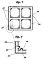
- the form 10 includes (see Figure 1) four moulds 20, each of which is in the shape of a rectangular frame.
- the moulds are made of steel and are rectangular.
- the shape and construction material can vary, however, in accordance with the specific requirements of their use.
- each rib 22 forms an isosceles trapezium with the shorter base 24 facing into the centre of the mould and extends into the centre of the mould 20 for a distance (corresponding in the case illustrated to the height 26 of the trapezium) of between 0.1% and 3% of the corresponding dimension 28 of the mould, and preferably of between 1% and 2% of this dimension.
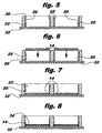
- the ribs 22 also have (see figure 5) an entry portion 30 which tapers towards the top.
- the ribs 22 can be formed in one piece with the walls of the mould 20 or may be produced separately and then applied thereto.
- the form 10 is first arranged on a base 32 (see Figure 5) and a slab 14, of stony material for example, is then lowered into each mould 20 (see Figures 6 and 7).
- a slab 14 of stony material for example
- the use of other materials for the slab is not ruled out, such as plastics, composites and the like.
- each dimension of the slab 14 is between 99.9% and 97%, and preferably between 99% and 98%, of the corresponding dimension of the mould 20.
- a layer of adhesive 34 is then preferably applied (see Figure 8) to the upwardly facing surface of the slab 14 and fresh cementitious material 16 is poured into the mould 20 (see Figure 9) to cover the slab 14 and fill the gaps between this latter and the walls of the mould 20, caused by the presence of the ribs 22.
- the cementitious material can be constituted by mortar, concrete or the like.
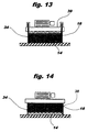
- the mould 20 is then subjected to vibro-compression with a tamper 36 (see Figure 10) using a conventional method, so that the cementitious material 16 is distributed uniformly within the mould 20 on top of the slab 14. Since the latter is in contact with the mould 20 only at the site of the narrow ribs 22, it is affected only by a reduced transmission of vibrations, which could otherwise fracture it and/or compromise the adhesion of the cementitious material 16.
- the mould 20 and the tamper 36 are then lifted (see Figure 11) and the cementitious material 16 is left to dry so that it hardens and adheres to the slab 14.
- an intermediate multi-layer product 38 (see Figure 12) is obtained, the dimensions of which do not yet correspond to those of the finished element 12 illustrated in Figures 2 and 3. There is an excess of cementitious material on the side walls which corresponds to the volume of the gaps which had been formed between the side walls of the mould 20 and the edges of the slab 14.
- This excess material is removed, by means of a grinding machine 39 for example (see Figure 13) in such a way that the portion of the cementitious layer 16 immediately adjacent the slab 14 is flush with it, with the spacer shoulder 18 left protruding from the base of the lower layer of cementitious material 16 (see Figures 2 and 3).
- the side walls of the intermediate product 38 are usually ground in two successive stages, first working on one pair of opposite walls and then on the remaining pair, by rotating the product 38 through 90°.
- the shoulder 18 extends continuously around the entire perimeter of the base of the element 12. In embodiments of the invention, not illustrated, it could have one or more interruptions.
- the two dimensions 40, 42 of the element 12 intended to lie parallel to the overall plane of the paving can be obtained with a tolerance which does not exceed an absolute value of 0.5 mm.
- the paving element 12 is subjected, in a manner known per se, to drying and sanding operations for surface finishing and for eliminating any traces of dirt, and is packed for forwarding to where it will be used.
- the fact that the transverse dimension 44 of the elements 12 is substantially constant ensures that the surface of the paving is regular, without bumps or differences of level, thereby providing clear advantages from the point of view both of aesthetics and of ease of use.
Landscapes
- Engineering & Computer Science (AREA)
- Chemical & Material Sciences (AREA)
- Ceramic Engineering (AREA)
- Mechanical Engineering (AREA)
- Structural Engineering (AREA)
- Road Paving Structures (AREA)
- Laminated Bodies (AREA)
- Floor Finish (AREA)
Applications Claiming Priority (2)
| Application Number | Priority Date | Filing Date | Title |
|---|---|---|---|
| IT1999TO000694A IT1310672B1 (it) | 1999-08-05 | 1999-08-05 | Elemento per pavimentazione autobloccante e suo procedimento diproduzione. |
| ITTO990694 | 1999-08-05 |
Publications (2)
| Publication Number | Publication Date |
|---|---|
| EP1074363A2 true EP1074363A2 (de) | 2001-02-07 |
| EP1074363A3 EP1074363A3 (de) | 2003-01-02 |
Family
ID=11418020
Family Applications (1)
| Application Number | Title | Priority Date | Filing Date |
|---|---|---|---|
| EP00116576A Withdrawn EP1074363A3 (de) | 1999-08-05 | 2000-08-01 | Verbundpflasterstein und Verfahren zu dessen Herstellung |
Country Status (2)
| Country | Link |
|---|---|
| EP (1) | EP1074363A3 (de) |
| IT (1) | IT1310672B1 (de) |
Cited By (1)
| Publication number | Priority date | Publication date | Assignee | Title |
|---|---|---|---|---|
| DE10124001C1 (de) * | 2001-05-17 | 2003-01-30 | Dasag Gmbh & Co Kg | Verfahren zur Herstellung von Betonwerksteinplatten |
Family Cites Families (7)
| Publication number | Priority date | Publication date | Assignee | Title |
|---|---|---|---|---|
| NL7305809A (en) * | 1973-04-26 | 1974-10-29 | Composite building blocks and tiles - obtd. by bonding relatively dry concrete mixt. to polyester laminate | |
| US5009387A (en) * | 1989-02-06 | 1991-04-23 | Scott Samuel C | Object retainer for upright concrete construction forms |
| JP2628501B2 (ja) * | 1992-01-22 | 1997-07-09 | 株式会社イナックス | ユニットタイルの製造方法 |
| DE4212702A1 (de) * | 1992-04-16 | 1993-10-21 | Schwenk Baustoffwerke Kg E | Verfahren und Vorrichtung zur Herstellung von Stein-Verbundplatten |
| JPH06317001A (ja) * | 1993-05-01 | 1994-11-15 | Inax Corp | 化粧コンクリート平板及び化粧コンクリート平板の製造方法とこれに用いる成形型 |
| DE29515331U1 (de) * | 1995-09-13 | 1996-02-15 | BauDG Baumarketing Development GmbH, 48734 Reken | Vorrichtung zur Herstellung von Natur-Verbundsteinen und Platten |
| DE19627148C1 (de) * | 1996-07-05 | 1997-11-20 | Paul Wasmer | Vorrichtung zum beidseitigen Beschleifen von Steinen |
-
1999
- 1999-08-05 IT IT1999TO000694A patent/IT1310672B1/it active
-
2000
- 2000-08-01 EP EP00116576A patent/EP1074363A3/de not_active Withdrawn
Cited By (2)
| Publication number | Priority date | Publication date | Assignee | Title |
|---|---|---|---|---|
| DE10124001C1 (de) * | 2001-05-17 | 2003-01-30 | Dasag Gmbh & Co Kg | Verfahren zur Herstellung von Betonwerksteinplatten |
| DE10124001C5 (de) * | 2001-05-17 | 2008-04-24 | Dasag Gmbh & Co. Kg | Verfahren zur Herstellung von Betonwerksteinplatten |
Also Published As
| Publication number | Publication date |
|---|---|
| ITTO990694A1 (it) | 2001-02-05 |
| EP1074363A3 (de) | 2003-01-02 |
| IT1310672B1 (it) | 2002-02-19 |
| ITTO990694A0 (it) | 1999-08-05 |
Similar Documents
| Publication | Publication Date | Title |
|---|---|---|
| US20180371705A1 (en) | Permeable surface covering units and permeable surface covering | |
| US20060056912A1 (en) | Concrete pavers layable in a herringbone pattern | |
| US8726595B2 (en) | Irregular building units having mating sides | |
| US3891340A (en) | Paving stone unit having integral connecting webs | |
| AU2008323852A1 (en) | Wall block with weight bearing pads and method of producing wall blocks | |
| US12043976B2 (en) | Masonry block | |
| EP1729942A1 (de) | Teilbare pflasterplatten | |
| ES2343622T3 (es) | Procedimiento para la fabricacion de baldosas o paneles reforzados de material aglomerado con una placa metalica asi como un producto obtenido mediante ese procedimiento. | |
| CN102041765A (zh) | 防滑车道 | |
| CN109252434A (zh) | 一种沥青路面结构及其施工方法 | |
| JP3133417U (ja) | 敷石用ブロック | |
| CN101228320B (zh) | 铺路石、用铺路石铺设路面的方法及生产铺路石的方法 | |
| KR20130037927A (ko) | 합성목재와 투수콘크리트가 일체화된 투수블록 | |
| EP1426517A2 (de) | Vorgefertigte Stahlbetonplatte mit der Sichtseite aus Naturstein oder dergleichen | |
| EP0039555B1 (de) | Strassenpflaster | |
| JP7665560B2 (ja) | 舗装材、及び、舗装面の施工方法 | |
| JPS6124562Y2 (de) | ||
| JPS6330201A (ja) | 異質材料を目地で仕切つたコンクリ−ト製品の製造方法 | |
| JPH0140163B2 (de) | ||
| JP2000230212A (ja) | 舗装用ブロックおよびその製造法並びに舗装工法 | |
| NL1011328C2 (nl) | Bouwblok en werkwijze voor de vervaardiging ervan. | |
| JPS61179903A (ja) | 天然木を舗装面とする舗装ブロック成形機 | |
| KR100741410B1 (ko) | 흡수성 포장층의 시공방법 | |
| JPH0440165B2 (de) | ||
| JPH06306806A (ja) | プレキャスト舗装版 |
Legal Events
| Date | Code | Title | Description |
|---|---|---|---|
| PUAI | Public reference made under article 153(3) epc to a published international application that has entered the european phase |
Free format text: ORIGINAL CODE: 0009012 |
|
| AK | Designated contracting states |
Kind code of ref document: A2 Designated state(s): AT BE CH CY DE DK ES FI FR GB GR IE IT LI LU MC NL PT SE |
|
| AX | Request for extension of the european patent |
Free format text: AL;LT;LV;MK;RO;SI |
|
| PUAL | Search report despatched |
Free format text: ORIGINAL CODE: 0009013 |
|
| AK | Designated contracting states |
Kind code of ref document: A3 Designated state(s): AT BE CH CY DE DK ES FI FR GB GR IE IT LI LU MC NL PT SE |
|
| AX | Request for extension of the european patent |
Free format text: AL;LT;LV;MK;RO;SI |
|
| RIC1 | Information provided on ipc code assigned before grant |
Free format text: 7B 28B 19/00 A, 7B 28B 3/02 B, 7B 28B 11/08 B, 7E 01C 5/22 B |
|
| AKX | Designation fees paid | ||
| REG | Reference to a national code |
Ref country code: DE Ref legal event code: 8566 |
|
| STAA | Information on the status of an ep patent application or granted ep patent |
Free format text: STATUS: THE APPLICATION IS DEEMED TO BE WITHDRAWN |
|
| 18D | Application deemed to be withdrawn |
Effective date: 20030703 |