EP1074461A2 - Halterungseinrichtung - Google Patents
Halterungseinrichtung Download PDFInfo
- Publication number
- EP1074461A2 EP1074461A2 EP00116328A EP00116328A EP1074461A2 EP 1074461 A2 EP1074461 A2 EP 1074461A2 EP 00116328 A EP00116328 A EP 00116328A EP 00116328 A EP00116328 A EP 00116328A EP 1074461 A2 EP1074461 A2 EP 1074461A2
- Authority
- EP
- European Patent Office
- Prior art keywords
- section
- connecting part
- lock
- shackle
- fastening
- Prior art date
- Legal status (The legal status is an assumption and is not a legal conclusion. Google has not performed a legal analysis and makes no representation as to the accuracy of the status listed.)
- Granted
Links
- 238000003780 insertion Methods 0.000 claims abstract description 41
- 230000037431 insertion Effects 0.000 claims abstract description 41
- 230000000295 complement effect Effects 0.000 claims abstract description 7
- 210000002414 leg Anatomy 0.000 description 26
- 238000013459 approach Methods 0.000 description 4
- 239000003795 chemical substances by application Substances 0.000 description 2
- 239000000463 material Substances 0.000 description 2
- 239000002184 metal Substances 0.000 description 2
- 210000000689 upper leg Anatomy 0.000 description 2
- 230000006978 adaptation Effects 0.000 description 1
- 230000006735 deficit Effects 0.000 description 1
- 230000001419 dependent effect Effects 0.000 description 1
- 230000000694 effects Effects 0.000 description 1
- 238000005516 engineering process Methods 0.000 description 1
- 238000007373 indentation Methods 0.000 description 1
- 238000010409 ironing Methods 0.000 description 1
- 238000004519 manufacturing process Methods 0.000 description 1
- 238000000034 method Methods 0.000 description 1
- 230000002093 peripheral effect Effects 0.000 description 1
- 238000003825 pressing Methods 0.000 description 1
- 230000000284 resting effect Effects 0.000 description 1
Images


Classifications
-
- B—PERFORMING OPERATIONS; TRANSPORTING
- B62—LAND VEHICLES FOR TRAVELLING OTHERWISE THAN ON RAILS
- B62J—CYCLE SADDLES OR SEATS; AUXILIARY DEVICES OR ACCESSORIES SPECIALLY ADAPTED TO CYCLES AND NOT OTHERWISE PROVIDED FOR, e.g. ARTICLE CARRIERS OR CYCLE PROTECTORS
- B62J11/00—Supporting arrangements specially adapted for fastening specific devices to cycles, e.g. supports for attaching maps
-
- B—PERFORMING OPERATIONS; TRANSPORTING
- B62—LAND VEHICLES FOR TRAVELLING OTHERWISE THAN ON RAILS
- B62H—CYCLE STANDS; SUPPORTS OR HOLDERS FOR PARKING OR STORING CYCLES; APPLIANCES PREVENTING OR INDICATING UNAUTHORIZED USE OR THEFT OF CYCLES; LOCKS INTEGRAL WITH CYCLES; DEVICES FOR LEARNING TO RIDE CYCLES
- B62H5/00—Appliances preventing or indicating unauthorised use or theft of cycles; Locks integral with cycles
-
- B—PERFORMING OPERATIONS; TRANSPORTING
- B62—LAND VEHICLES FOR TRAVELLING OTHERWISE THAN ON RAILS
- B62H—CYCLE STANDS; SUPPORTS OR HOLDERS FOR PARKING OR STORING CYCLES; APPLIANCES PREVENTING OR INDICATING UNAUTHORIZED USE OR THEFT OF CYCLES; LOCKS INTEGRAL WITH CYCLES; DEVICES FOR LEARNING TO RIDE CYCLES
- B62H5/00—Appliances preventing or indicating unauthorised use or theft of cycles; Locks integral with cycles
- B62H2005/008—Arrangements or adaptations for supporting U-locks on cycles
Definitions
- the invention relates to a mounting device for detachable mounting of a U-lock having a cylindrical shackle section a two-wheeler, with a two-wheel-side fastening part, which has a fastening section for permanent fastening of the fastening part has the two-wheeler, and with a lock-side connecting part for Enabling a plug connection in a variable angular position between the padlock and the two-wheeler.
- Such a mounting device allows temporary attachment the lock on the two-wheeler, in particular on a bicycle or Motorbike, for example to carry the lock with you while driving.
- the fastening part acts for this temporary holding of the lock and the connecting part in a connector.
- Angular position of the lock relative to the fastening part fastened to the two-wheeler can be variably selected and set by the user.
- Such a mounting device is known from EP 0 832 812 A2 Bracket of a U-lock known, which is attached to the two-wheeler and has a hollow cylindrical push-through channel.
- a thigh casing sleeve is attached to the padlock, those for carrying the lock while driving into the push-through channel the two-wheel-side mounting device is used.
- Anti-rotation ribs or grooves are provided for inserting the stirrup leg in a corresponding grid of different angular positions enable and a twisting of the inserted stirrup leg prevent.
- a disadvantage of the known mounting devices is that they - themselves when choosing a small pitch angle - not a completely free choice of Allow angular position of the attached lock, and that too the lock attachment is not easy to accomplish.
- the connecting part has a sleeve portion which has the shackle section of the shackle lock in a rotatable manner Way encompasses permanently, with an angular fixation means selectable angular position of connecting part and shackle section of the shackle lock is adjustable relative to each other and wherein the sleeve section the bracket section preferably in a continuously rotatable Encompasses manner; that further the connecting part with respect to the longitudinal axis of the sleeve section radially outward insertion element and the fastening part is complementary to the insertion element Has insertion counterpart, the insertion element and Allow insertion counterpart with each other a rail / groove connector; and that the connector between the connecting part and Fastening direction can be secured by locking the U-lock is.
- the connecting part is therefore permanent, with the angle fixing agent loosened however in a rotatable manner on the shackle portion of the lock attached.
- This bracket section is typically a longitudinal section of a leg of the U-lock.
- connection between the lock and the two-wheeler is made via a rail / groove connector, the with respect to the longitudinal axis of the bracket portion of the lock is offset radially outwards, that is, arranged eccentrically.
- a particular advantage of the invention is that the desired Angular position can be set and fixed once by the user, so that the user does not change the angular position with every mounting process must search again or select, as is the case with the grid solution of the State of the art is the case.
- the invention enables a particularly simple accomplishment the plug-in connection between the lock and the two-wheeler, because that is for this provided insertion element and insertion counterpart on the outside provided by connecting part or fastening part and therefore are clearly visible to the user.
- the State of the art covers the angular division grid for the user, so that when inserting the lock - even if additional provision is made Centering aids - a "re-turning" of the same, ie a searching rotary movement may be required.
- the invention also avoids immediate impairment of the castle structure.
- it is for the provision of the invention Bracket not required on the lock to add a notch or an additional approach that is considered undesirable Attack point for a violent opening of the locked Castle could serve.
- the angular position between the lock and the two-wheeler - in contrast to the grid solution of the prior art - can take place continuously.
- the user is therefore not dependent on the pitch angle specified by the manufacturer, but can set any intermediate levels or angular positions.
- the pitch angle in the prior art cannot be chosen arbitrarily small by the manufacturer.
- the dividing means in particular cooperating ribs and grooves, simultaneously secure the lock against unintentional twisting, so that a further reduction in the dividing angle and the associated reduction in the material thickness of the dividing means or anti-rotation means would come at the expense of stability and break resistance.
- the rail / groove plug connection between the insertion element of the connecting part and Insertion counterpart of the fastening part realized in that the insertion element as an elongated anchor rail T-shaped cross section and that Insertion counterpart as a complementary receiving groove with an im Cross-section C-shaped border is formed, or vice versa.
- the said angle fixing agent at least by a frictional engagement between the sleeve portion of the Connection part and the bracket portion of the castle is formed, wherein the frictional torque achieved by that torque that from the weight of the held lock results, preferably exceeds.
- the inner diameter of the sleeve section the outside diameter of the shackle portion of the lock corresponds, in particular in the form of a press fit.
- the bracket section is particularly in this context the outer diameter of the metal core of a stirrup leg without one possible plastic sheathing surrounding the stirrup leg elsewhere to understand, or the outer diameter of a stirrup leg including such a plastic jacket.
- angle fixing means can be replaced by an in the connecting part held fixing screw be formed, the front end attacks on the bracket portion of the castle, in particular radially with respect to the longitudinal direction of the bracket section.
- the connecting part can still be rotated continuously relative to the U-lock can be both the inner peripheral surface of the sleeve portion of the connecting part as well as the outer surface of the bracket portion of the Castle preferably formed sufficiently smooth. To make it possible These two surfaces therefore do not have a continuous rotatability mutually complementary toothing or longitudinal grooves / ribs.
- the connecting part and / or the fastening part has at least one stop element which has an axial relative movement of these two parts, especially an insertion movement limited to implement the rail / groove connection mentioned.
- Figure 1 shows a padlock that a mounting device on a Part of a bicycle frame 11 is held.
- the U-lock has a U-shaped bracket 13, which consists essentially of metal and in a lock body 15 is locked.
- the mounting device points to a connecting part 17, which has a bracket leg 19 of the lock bracket 13 encompasses.
- the mounting device has one Fastening part 21 which is fixed to the bicycle frame 11 and with the Connection part 17 is plug-in.
- the connecting part 17 and that Fastening part 21 are made of plastic.
- Figure 2 shows the bracket leg 19 without the lock body 15.
- the stirrup leg 19 is partially provided with a plastic jacket 23.
- On theirs front end includes for receiving the connecting part 17 provided bracket leg portion 24.
- the bracket leg 19 has a locking indentation 25 and a frusto-conical insertion tip 27.
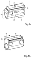
- FIGS. 3a to 3g show further details of the connecting part 17.
- This has a clamp for fastening to the bracket leg 19 hollow cylindrical sleeve section 29.
- T-shaped anchor rail serving as an insertion element 31 molded.
- the anchor rail 31 is on its - with respect to one Insertion direction 33 - chamfered front end and at its rear end provided with a stop element in the form of an end face attachment 35, which is perpendicular to the insertion direction 33 and across the cross section the anchor rail 31 extends (Fig. 3b and 3e).
- the sleeve section is in a central section of the connecting part 17 29 and the anchor rail 31 to one another via a connecting block 37 connected.
- This has a nut pocket 39 which is parallel extends to the insertion direction 33 and only to one long side of the connecting part 17 is open.
- the nut pocket 39 penetrated by a screw shaft 41, which extends through the Anchor rail 31 and the connecting block 37 into the inner cavity of the sleeve section 29 extends perpendicular to the insertion direction 33.
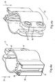
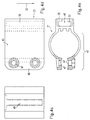
- the fastening part 21 a fastening portion 43 which is for permanent fixation on the Bicycle frame 11 is used and the shape of a longitudinally slotted hollow cylinder has.
- On the free longitudinal edges of the fastening section 43 are two mutually opposite fastening tabs 45 formed, which each have two screw openings 47, each with the Screw opening 47 of the opposite fastening tab 45 aligned.
- T-shaped receiving groove 49 provided by one on the attachment portion 43 molded, longitudinally slotted receiving frame 50 C-shaped cross section is formed and which is parallel to the longitudinal axis of the fastening portion 43 or extends to the insertion direction 33.
- the receiving groove 49 is complementary to the anchor rail as an insertion counterpart 31 of the connecting part 17 is formed.
- the end of the receiving frame opposite the insertion direction 33 50 is chamfered.
- the end of the receiving frame pointing in the insertion direction 33 50 is closed by an end face shoulder 51 (Fig. 4a).
- the bracket leg section 24 of the bracket leg 19 is factory-made the connecting part 17 is placed, as indicated in Fig. 2. Because of a Friction or a clamping effect between the connecting part 17 and the bracket leg section 24 can be put on Connecting part 17 only using a minimum torque or a minimum force are rotated or shifted.
- the user first attaches the fastening part 21 to the bicycle Bicycle frame 11 by the fastening portion 43 the frame 11 grips and there by means of two screws that pass through the screw openings 47 are carried out, is clamped.
- the user puts the bracket 13 with the attached connecting part 17, and without lock body 15, such in the insertion direction 33 in the fastening part 21 that the anchor rail 31 (Fig. 3a) in the receiving groove 49 of the receiving frame 50 (Fig. 4a) engages.
- the user can by overcoming the frictional moment between the stirrup legs 19 and the connecting part 17 and by corresponding stepless rotation of the bracket 13 the desired angular position of the bracket 13 adjust relative to the bicycle frame 11.
- Fixing screw 53 which is designed as a grub screw and in the Screw shaft 41 of the connecting part 17 is arranged with a Nut 55 is screwed, which is inserted laterally into the nut pocket 39 is (Fig. 3e).
- This screw fixes the tip of the fixing screw 53, which can also be conically pointed, on the lateral surface of the leg portion 24 pressed so that the connecting part 17 with regard to its angular position and its axial position is fixed relative to the bracket leg 19.
- the user can use the anchor rail 31, which is clearly visible from the outside and the receiving frame 50 the required connector without accomplish further, the bracket 13 automatically the desired and occupies a one-time fixed angular position.
- a clamp connection can be provided.
- the fastening part 21 can be used instead of gripping a section of the bicycle frame 11 also on a portion of a luggage rack or an accessory, and / or attached to a motorcycle his.
- the invention also applies to a cable lock, in particular a spiral cable lock can be realized, wherein a section of the lock cable, in particular including it Plastic sheath, as the mentioned bracket section or bracket leg section can serve.
Landscapes
- Engineering & Computer Science (AREA)
- Mechanical Engineering (AREA)
- Clamps And Clips (AREA)
- Pens And Brushes (AREA)
- Spinning Or Twisting Of Yarns (AREA)
- Chair Legs, Seat Parts, And Backrests (AREA)
- Details Of Connecting Devices For Male And Female Coupling (AREA)
Abstract
Description
Demgegenüber kann der Teilungswinkel beim Stand der Technik vom Hersteller nicht beliebig gering gewählt werden. Die Teilungsmittel, insbesondere zusammenwirkende Rippen und Nuten, sichern nämlich gleichzeitig das Schloß gegen ein unbeabsichtigtes Verdrehen, so daß eine weitere Verringerung des Teilungswinkels und die damit verbundene Verringerung der Materialstürke des Teilungsmittels bzw. Drehsicherungsmittels zu Lasten der Stabilität und Bruchsicherheit gehen würde.
- Figur 1
- ein an einem Rahmenteil gehaltenes Bügelschloß,
- Figur 2
- einen Schenkel des Schlosses gemäß Figur 1,
- Figuren 3a - 3g
- eine Perspektivansicht eines Verbindungsteils, eine weitere Perspektivansicht des Verbindungsteils, eine Seitenansicht des Verbindungsteils, eine Querschnittsansicht entlang der Ebene IIId - IIId, eine Querschnittsansicht entlang der Ebene IIIe - IIIe, eine weitere Seitenansicht sowie eine Querschnittsansicht entlang der Ebene IIIg - IIIg, und
- Figuren 4a - 4e
- eine Perspektivansicht eines Befestigungsteils, eine weitere Perspektivansicht des Befestigungsteils, eine Frontansicht, eine Seitenansicht sowie eine Draufsicht des Befestigungsteils.
- 11
- Fahrradrahmen
- 13
- Bügel
- 15
- Schloßkörper
- 17
- Verbindungsteil
- 19
- Bügelschenkel
- 21
- Befestigungsteil
- 23
- Kunststoffummantelung
- 24
- Bügelschenkelabschnitt
- 25
- Verriegelungseinbuchung
- 27
- Einführspitze
- 29
- Hülsenabschnitt
- 31
- Ankerschiene
- 33
- Einsteckrichtung
- 35
- Stirnflächenansatz
- 37
- Verbindungsblock
- 39
- Mutterntasche
- 41
- Schraubenschacht
- 43
- Befestigungsabschnitt
- 45
- Befestigungslasche
- 47
- Schraubenöffnung
- 49
- Aufnahmenut
- 50
- Aufnahmerahmen
- 51
- Stirnflächenansatz
- 53
- Fixierschraube
- 55
- Mutter
Claims (10)
- Halterungseinrichtung zur lösbaren Halterung eines einen zylindrischen Bügelabschnitt (24) aufweisenden Bügelschlosses (13) an einem Zweirad (11),dadurch gekennzeichnet,mit einem zweiradseitigen Befestigungsteil (21), das einen Befestigungsabschnitt (43) zur dauerhaften Befestigung des Befestigungsteils (21) an dem Zweirad (11) aufweist, sowiemit einem schloßseitigen Verbindungsteil (17) zur Ermöglichung einer in variabler Winkelstellung erfolgenden Steckverbindung zwischen dem Bügelschloß (13) und dem Zweirad (11);
daß das Verbindungsteil (17) einen Hülsenabschnitt (29) aufweist, der den Bügelabschnitt (24) des Bügelschlosses (13) in drehbeweglicher Weise dauerhaft umgreift, wobei mittels eines Winkelfixierungsmittels eine wählbare Winkelstellung von Verbindungsteil (17) und Bügelabschnitt (24) des Bügelschlosses relativ zueinander einstellbar ist und wobei der Hülsenabschnitt (29) den Bügelabschnitt (24) vorzugsweise in stufenlos drehbeweglicher Weise umgreift; daß ferner das Verbindungsteil (17) ein bezüglich der Längsachse des Hülsenabschnitts (29) radial nach außen versetztes Einführelement (31) aufweist und das Befestigungsteil (21) ein zu dem Einführelement (31) komplementäres Einführgegenstück (49) aufweist, wobei das Einführelement (31) und das Einführgegenstück (49) miteinander eine Schienen-/Nut-Steckverbindung ermöglichen; und daß die Steckverbindung zwischen Verbindungsteil (17) und Befestigungsteil (21) durch Verriegeln des Bügelschlosses (13) sicherbar ist. - Halterungseinrichtung nach Anspruch 1,
dadurch gekennzeichnet,
daß das Einführelement als eine im Querschnitt T-förmige Ankerschiene (31) und das Einführgegenstück als eine Aufnahmenut (49) mit hierzu komplementärem Querschnitt ausgebildet ist, oder umgekehrt. - Halterungseinrichtung nach einem der vorhergehenden Ansprüche,
dadurch gekennzeichnet,
daß der Innendurchmesser des Hülsenabschnitts (29) dem Außendurchmesser des Bügelabschnitts (24) entspricht. - Halterungseinrichtung nach einem der vorhergehenden Ansprüche,
dadurch gekennzeichnet,
daß die Innenumfangsfläche des Hülsenabschnitts (29) und die Außenmantelfläche des Bügelabschnitts (24) dergestalt glatt ausgebildet sind, daß bei deaktiviertem Winkelfixierungsmittel das Verbindungsteil (17) und der Bügelabschnitt (24) des Bügelschlosses (13) - insbesondere bei Anwendung eines bestimmten Mindestdrehmoments - stufenlos relativ zueinander verdrehbar sind. - Halterungseinrichtung nach einem der vorhergehenden Ansprüche,
dadurch gekennzeichnet,
daß das Winkelfixierungsmittel durch eine an dem Verbindungsteil vorgesehene Fixierschraube (53) gebildet ist, deren Spitze an den Bügelabschnitt (24) des Bügelschlosses (13) heranführbar ist. - Halterungseinrichtung nach einem der vorhergehenden Ansprüche,
dadurch gekennzeichnet,
daß das Winkelfixierungsmittel durch einen Reibungsschluß zwischen Hülsenabschnitt (29) und Bügelabschnitt (24) gebildet ist, dessen Reibungsmoment das von der Gewichtskraft des gehaltenen Bügelschlosses (13, 15) resultierende Drehmoment vorzugsweise übersteigt. - Halterungseinrichtung nach einem der vorhergehenden Ansprüche,
dadurch gekennzeichnet,
daß der Hülsenabschnitt (29) des Verbindungsteils (17) an dem Bügelschloß in axialer Richtung durch das Winkelfixierungsmittel, durch Anliegen an einer Ummantelung (23) des Bügelschlosses (13), durch Anliegen an einem Schloßkörper (15) des Bügelschlosses und/oder durch einen Nocken-/Ringnut-Eingriff zwischen Verbindungsteil und Bügelschloß fixiert ist. - Halterungseinrichtung nach einem der vorhergehenden Ansprüche,
dadurch gekennzeichnet,
daß an dem Verbindungsteil (17) und/oder dem Befestigungsteil (21) wenigstens ein Anschlagelement (35, 51) vorgesehen ist, das eine Einsteckbewegung (33) des Verbindungsteils (17) relativ zu dem Befestigungsteil (21) in axialer Richtung begrenzt,
wobei das Anschlagelement vorzugsweise als ein Stirnflächenansatz (35 bzw. 51) an einem Ende des Einführelements (31) und/oder des Einführgegenstücks (49) ausgebildet ist. - Halterungseinrichtung nach einem der vorhergehenden Ansprüche,
dadurch gekennzeichnet,
daß die Längsrichtung des Hülsenabschnitts (29) des Verbindungsteils (17) parallel zu der Längsrichtung des Befestigungsabschnitts (43) des steckverbundenen Befestigungsteils (21) verläuft. - Halterungseinrichtung nach einem der vorhergehenden Ansprüche,
dadurch gekennzeichnet,
daß der Befestigungsabschnitt (43) des Befestigungsteils (21) einen Teil des Zweirads, insbesondere einen Rahmenabschnitt (11), umgreift, und zwar insbesondere mit einem C-förmigen Querschnitt und/oder mittels einer Fixierschelle.
Applications Claiming Priority (2)
| Application Number | Priority Date | Filing Date | Title |
|---|---|---|---|
| DE19937233A DE19937233A1 (de) | 1999-08-06 | 1999-08-06 | Halterungseinrichtung |
| DE19937233 | 1999-08-06 |
Publications (3)
| Publication Number | Publication Date |
|---|---|
| EP1074461A2 true EP1074461A2 (de) | 2001-02-07 |
| EP1074461A3 EP1074461A3 (de) | 2002-09-18 |
| EP1074461B1 EP1074461B1 (de) | 2003-10-22 |
Family
ID=7917498
Family Applications (1)
| Application Number | Title | Priority Date | Filing Date |
|---|---|---|---|
| EP00116328A Expired - Lifetime EP1074461B1 (de) | 1999-08-06 | 2000-07-27 | Halterungseinrichtung |
Country Status (3)
| Country | Link |
|---|---|
| EP (1) | EP1074461B1 (de) |
| AT (1) | ATE252481T1 (de) |
| DE (2) | DE19937233A1 (de) |
Cited By (6)
| Publication number | Priority date | Publication date | Assignee | Title |
|---|---|---|---|---|
| CN102862623A (zh) * | 2012-09-18 | 2013-01-09 | 蒋海啸 | 一种自行车遮阳伞基座 |
| CN102862624A (zh) * | 2012-09-18 | 2013-01-09 | 蒋海啸 | 自行车遮阳伞基座 |
| CN102862626A (zh) * | 2012-09-18 | 2013-01-09 | 蒋海啸 | 一种自行车遮阳伞基座改进结构 |
| CN102862627A (zh) * | 2012-09-18 | 2013-01-09 | 蒋海啸 | 可调节遮阳伞角度的自行车遮阳伞基座 |
| GB2516460A (en) * | 2013-07-22 | 2015-01-28 | Plus 8 Ind Ltd | A security device |
| US20180142503A1 (en) * | 2011-05-25 | 2018-05-24 | Schlage Lock Company Llc | Portable lock mounting assemblies |
Citations (1)
| Publication number | Priority date | Publication date | Assignee | Title |
|---|---|---|---|---|
| EP0832812A2 (de) | 1996-09-26 | 1998-04-01 | Aug. Winkhaus GmbH & Co. KG | Halterungseinrichtung zur Halterung eines Bügelschlosses |
Family Cites Families (6)
| Publication number | Priority date | Publication date | Assignee | Title |
|---|---|---|---|---|
| EP0360335A3 (de) * | 1988-09-20 | 1990-11-07 | Guillermo Diaz-Miguel Sanchez | Träger für Sicherheitsvorrichtungen für Zweiräder |
| US5167353A (en) * | 1990-03-27 | 1992-12-01 | Hughes Jack I | "U" post bracket for bicycles |
| DE4312032C3 (de) * | 1992-04-14 | 1999-09-23 | Rixen & Kaul Gmbh | Kupplung zum Befestigen und Lösen von Ausrüstungsgegenständen |
| DE4312033C2 (de) * | 1992-05-12 | 1998-02-12 | Rixen & Kaul Gmbh | Halterung für ein oder mit einem tragbaren Schloß |
| US5386961A (en) * | 1993-04-26 | 1995-02-07 | Interseng Hardware Company L.T.D. | Multi-directional mounting unit for mounting a bicycle lock on a tubular frame |
| US5669536A (en) * | 1996-07-09 | 1997-09-23 | Wang; Lopin | Device for locating shackle lock on bicycle frame |
-
1999
- 1999-08-06 DE DE19937233A patent/DE19937233A1/de not_active Withdrawn
-
2000
- 2000-07-27 EP EP00116328A patent/EP1074461B1/de not_active Expired - Lifetime
- 2000-07-27 AT AT00116328T patent/ATE252481T1/de not_active IP Right Cessation
- 2000-07-27 DE DE50004135T patent/DE50004135D1/de not_active Expired - Lifetime
Patent Citations (1)
| Publication number | Priority date | Publication date | Assignee | Title |
|---|---|---|---|---|
| EP0832812A2 (de) | 1996-09-26 | 1998-04-01 | Aug. Winkhaus GmbH & Co. KG | Halterungseinrichtung zur Halterung eines Bügelschlosses |
Cited By (9)
| Publication number | Priority date | Publication date | Assignee | Title |
|---|---|---|---|---|
| US20180142503A1 (en) * | 2011-05-25 | 2018-05-24 | Schlage Lock Company Llc | Portable lock mounting assemblies |
| US10711491B2 (en) * | 2011-05-25 | 2020-07-14 | Schlage Lock Company Llc | Portable lock mounting assemblies |
| CN102862623A (zh) * | 2012-09-18 | 2013-01-09 | 蒋海啸 | 一种自行车遮阳伞基座 |
| CN102862624A (zh) * | 2012-09-18 | 2013-01-09 | 蒋海啸 | 自行车遮阳伞基座 |
| CN102862626A (zh) * | 2012-09-18 | 2013-01-09 | 蒋海啸 | 一种自行车遮阳伞基座改进结构 |
| CN102862627A (zh) * | 2012-09-18 | 2013-01-09 | 蒋海啸 | 可调节遮阳伞角度的自行车遮阳伞基座 |
| GB2516460A (en) * | 2013-07-22 | 2015-01-28 | Plus 8 Ind Ltd | A security device |
| WO2015011464A1 (en) * | 2013-07-22 | 2015-01-29 | Plus 8 Industries Limited | A security device |
| US9822559B2 (en) | 2013-07-22 | 2017-11-21 | Plus 8 Industries Limited | Security device |
Also Published As
| Publication number | Publication date |
|---|---|
| DE50004135D1 (de) | 2003-11-27 |
| EP1074461B1 (de) | 2003-10-22 |
| ATE252481T1 (de) | 2003-11-15 |
| DE19937233A1 (de) | 2001-02-15 |
| EP1074461A3 (de) | 2002-09-18 |
Similar Documents
| Publication | Publication Date | Title |
|---|---|---|
| EP1946997B1 (de) | Halterung | |
| DE69018254T2 (de) | Verbessertes Fahrradschloss. | |
| EP0361155B1 (de) | Halterung für ein Langbügelschloss | |
| DE202004014766U1 (de) | Griff zur Montage in einem Durchbruch | |
| DE10127515C2 (de) | Schaltgriff | |
| DE19929093A1 (de) | Rotorsystem für ein Fahrrad | |
| EP1111249A2 (de) | Klemmvorrichtung | |
| EP1074461B1 (de) | Halterungseinrichtung | |
| EP0541736B1 (de) | Schnellspannabe für fahrräder | |
| DE2713411C3 (de) | Vorrichtung zur Diebstahlsicherung eines Motorradschutzhelms | |
| EP0476260B1 (de) | Halterungseinrichtung Stichwort: Kabelschlossbefestigung an einem Zweiradrahmen | |
| EP1416110B1 (de) | Rahmenschloss für ein Zweirad | |
| EP3144544B1 (de) | Gelenkanordnung zur positionierung von bauteilen | |
| DE1755273C3 (de) | Abschließbarer Skitrager für Kraftfahrzeuge | |
| DE202014102320U1 (de) | Fahrradrahmenadapter | |
| EP0638257B1 (de) | Haltevorrichtung für Stangen, Rohre oder dergleichen | |
| DE9310011U1 (de) | Bügelschloß mit Halter | |
| EP0763640B1 (de) | Schliessvorrichtung | |
| DE4244895C2 (de) | Vorrichtung zur Halterung von Bügelschlössern und dergleichen an Zweirädern | |
| EP1712458B1 (de) | Einheit versehen mit einem Fahrradschloss | |
| DE10042821C2 (de) | Anschließvorrichtung für Fahrräder | |
| DE2506130C2 (de) | Türband | |
| EP1352820B1 (de) | Zubehörbefestigungseinrichtung für Zweiräder | |
| EP0884236B1 (de) | Befestigungsvorrichtung | |
| EP1116838A1 (de) | Schutzbeschlag |
Legal Events
| Date | Code | Title | Description |
|---|---|---|---|
| PUAI | Public reference made under article 153(3) epc to a published international application that has entered the european phase |
Free format text: ORIGINAL CODE: 0009012 |
|
| AK | Designated contracting states |
Kind code of ref document: A2 Designated state(s): AT BE CH CY DE DK ES FI FR GB GR IE IT LI LU MC NL PT SE |
|
| AX | Request for extension of the european patent |
Free format text: AL;LT;LV;MK;RO;SI |
|
| PUAL | Search report despatched |
Free format text: ORIGINAL CODE: 0009013 |
|
| AK | Designated contracting states |
Kind code of ref document: A3 Designated state(s): AT BE CH CY DE DK ES FI FR GB GR IE IT LI LU MC NL PT SE |
|
| AX | Request for extension of the european patent |
Free format text: AL;LT;LV;MK;RO;SI |
|
| 17P | Request for examination filed |
Effective date: 20021202 |
|
| GRAH | Despatch of communication of intention to grant a patent |
Free format text: ORIGINAL CODE: EPIDOS IGRA |
|
| AKX | Designation fees paid |
Designated state(s): AT BE CH CY DE DK ES FI FR GB GR IE IT LI LU MC NL PT SE |
|
| GRAS | Grant fee paid |
Free format text: ORIGINAL CODE: EPIDOSNIGR3 |
|
| GRAA | (expected) grant |
Free format text: ORIGINAL CODE: 0009210 |
|
| AK | Designated contracting states |
Kind code of ref document: B1 Designated state(s): AT BE CH CY DE DK ES FI FR GB GR IE IT LI LU MC NL PT SE |
|
| PG25 | Lapsed in a contracting state [announced via postgrant information from national office to epo] |
Ref country code: FI Free format text: LAPSE BECAUSE OF FAILURE TO SUBMIT A TRANSLATION OF THE DESCRIPTION OR TO PAY THE FEE WITHIN THE PRESCRIBED TIME-LIMIT Effective date: 20031022 Ref country code: IT Free format text: LAPSE BECAUSE OF FAILURE TO SUBMIT A TRANSLATION OF THE DESCRIPTION OR TO PAY THE FEE WITHIN THE PRESCRIBED TIME-LIMIT;WARNING: LAPSES OF ITALIAN PATENTS WITH EFFECTIVE DATE BEFORE 2007 MAY HAVE OCCURRED AT ANY TIME BEFORE 2007. THE CORRECT EFFECTIVE DATE MAY BE DIFFERENT FROM THE ONE RECORDED. Effective date: 20031022 Ref country code: IE Free format text: LAPSE BECAUSE OF FAILURE TO SUBMIT A TRANSLATION OF THE DESCRIPTION OR TO PAY THE FEE WITHIN THE PRESCRIBED TIME-LIMIT Effective date: 20031022 Ref country code: CY Free format text: LAPSE BECAUSE OF FAILURE TO SUBMIT A TRANSLATION OF THE DESCRIPTION OR TO PAY THE FEE WITHIN THE PRESCRIBED TIME-LIMIT Effective date: 20031022 |
|
| REG | Reference to a national code |
Ref country code: GB Ref legal event code: FG4D Free format text: NOT ENGLISH |
|
| REG | Reference to a national code |
Ref country code: CH Ref legal event code: EP |
|
| REG | Reference to a national code |
Ref country code: IE Ref legal event code: FG4D Free format text: GERMAN |
|
| REF | Corresponds to: |
Ref document number: 50004135 Country of ref document: DE Date of ref document: 20031127 Kind code of ref document: P |
|
| PG25 | Lapsed in a contracting state [announced via postgrant information from national office to epo] |
Ref country code: DK Free format text: LAPSE BECAUSE OF FAILURE TO SUBMIT A TRANSLATION OF THE DESCRIPTION OR TO PAY THE FEE WITHIN THE PRESCRIBED TIME-LIMIT Effective date: 20040122 Ref country code: GR Free format text: LAPSE BECAUSE OF FAILURE TO SUBMIT A TRANSLATION OF THE DESCRIPTION OR TO PAY THE FEE WITHIN THE PRESCRIBED TIME-LIMIT Effective date: 20040122 |
|
| PG25 | Lapsed in a contracting state [announced via postgrant information from national office to epo] |
Ref country code: ES Free format text: LAPSE BECAUSE OF FAILURE TO SUBMIT A TRANSLATION OF THE DESCRIPTION OR TO PAY THE FEE WITHIN THE PRESCRIBED TIME-LIMIT Effective date: 20040202 |
|
| REG | Reference to a national code |
Ref country code: SE Ref legal event code: TRGR |
|
| GBT | Gb: translation of ep patent filed (gb section 77(6)(a)/1977) |
Effective date: 20040117 |
|
| REG | Reference to a national code |
Ref country code: IE Ref legal event code: FD4D |
|
| ET | Fr: translation filed | ||
| PGFP | Annual fee paid to national office [announced via postgrant information from national office to epo] |
Ref country code: BE Payment date: 20040723 Year of fee payment: 5 Ref country code: LU Payment date: 20040723 Year of fee payment: 5 |
|
| PG25 | Lapsed in a contracting state [announced via postgrant information from national office to epo] |
Ref country code: AT Free format text: LAPSE BECAUSE OF NON-PAYMENT OF DUE FEES Effective date: 20040727 |
|
| PG25 | Lapsed in a contracting state [announced via postgrant information from national office to epo] |
Ref country code: MC Free format text: LAPSE BECAUSE OF NON-PAYMENT OF DUE FEES Effective date: 20040731 Ref country code: CH Free format text: LAPSE BECAUSE OF NON-PAYMENT OF DUE FEES Effective date: 20040731 Ref country code: LI Free format text: LAPSE BECAUSE OF NON-PAYMENT OF DUE FEES Effective date: 20040731 |
|
| PLBE | No opposition filed within time limit |
Free format text: ORIGINAL CODE: 0009261 |
|
| STAA | Information on the status of an ep patent application or granted ep patent |
Free format text: STATUS: NO OPPOSITION FILED WITHIN TIME LIMIT |
|
| 26N | No opposition filed |
Effective date: 20040723 |
|
| REG | Reference to a national code |
Ref country code: CH Ref legal event code: PL |
|
| PGFP | Annual fee paid to national office [announced via postgrant information from national office to epo] |
Ref country code: NL Payment date: 20050714 Year of fee payment: 6 Ref country code: SE Payment date: 20050714 Year of fee payment: 6 |
|
| PG25 | Lapsed in a contracting state [announced via postgrant information from national office to epo] |
Ref country code: LU Free format text: LAPSE BECAUSE OF NON-PAYMENT OF DUE FEES Effective date: 20050727 |
|
| PG25 | Lapsed in a contracting state [announced via postgrant information from national office to epo] |
Ref country code: BE Free format text: LAPSE BECAUSE OF NON-PAYMENT OF DUE FEES Effective date: 20050731 |
|
| PG25 | Lapsed in a contracting state [announced via postgrant information from national office to epo] |
Ref country code: SE Free format text: LAPSE BECAUSE OF NON-PAYMENT OF DUE FEES Effective date: 20060728 |
|
| PG25 | Lapsed in a contracting state [announced via postgrant information from national office to epo] |
Ref country code: NL Free format text: LAPSE BECAUSE OF NON-PAYMENT OF DUE FEES Effective date: 20070201 |
|
| EUG | Se: european patent has lapsed | ||
| NLV4 | Nl: lapsed or anulled due to non-payment of the annual fee |
Effective date: 20070201 |
|
| BERE | Be: lapsed |
Owner name: ABUS AUGUST *REMICKER SOHNE K.G. Effective date: 20050731 |
|
| PG25 | Lapsed in a contracting state [announced via postgrant information from national office to epo] |
Ref country code: PT Free format text: LAPSE BECAUSE OF NON-PAYMENT OF DUE FEES Effective date: 20040322 |
|
| REG | Reference to a national code |
Ref country code: FR Ref legal event code: PLFP Year of fee payment: 17 |
|
| REG | Reference to a national code |
Ref country code: FR Ref legal event code: PLFP Year of fee payment: 18 |
|
| REG | Reference to a national code |
Ref country code: FR Ref legal event code: PLFP Year of fee payment: 19 |
|
| PGFP | Annual fee paid to national office [announced via postgrant information from national office to epo] |
Ref country code: FR Payment date: 20180725 Year of fee payment: 19 |
|
| PGFP | Annual fee paid to national office [announced via postgrant information from national office to epo] |
Ref country code: GB Payment date: 20180719 Year of fee payment: 19 |
|
| PGFP | Annual fee paid to national office [announced via postgrant information from national office to epo] |
Ref country code: DE Payment date: 20180928 Year of fee payment: 19 |
|
| REG | Reference to a national code |
Ref country code: DE Ref legal event code: R119 Ref document number: 50004135 Country of ref document: DE |
|
| GBPC | Gb: european patent ceased through non-payment of renewal fee |
Effective date: 20190727 |
|
| PG25 | Lapsed in a contracting state [announced via postgrant information from national office to epo] |
Ref country code: GB Free format text: LAPSE BECAUSE OF NON-PAYMENT OF DUE FEES Effective date: 20190727 Ref country code: DE Free format text: LAPSE BECAUSE OF NON-PAYMENT OF DUE FEES Effective date: 20200201 |
|
| PG25 | Lapsed in a contracting state [announced via postgrant information from national office to epo] |
Ref country code: FR Free format text: LAPSE BECAUSE OF NON-PAYMENT OF DUE FEES Effective date: 20190731 |