EP1074484A1 - Agencement de soupape pour récipient distributeur de fluides stockés sous pression - Google Patents
Agencement de soupape pour récipient distributeur de fluides stockés sous pression Download PDFInfo
- Publication number
- EP1074484A1 EP1074484A1 EP00810673A EP00810673A EP1074484A1 EP 1074484 A1 EP1074484 A1 EP 1074484A1 EP 00810673 A EP00810673 A EP 00810673A EP 00810673 A EP00810673 A EP 00810673A EP 1074484 A1 EP1074484 A1 EP 1074484A1
- Authority
- EP
- European Patent Office
- Prior art keywords
- valve
- valve plate
- pressure
- arrangement according
- valve arrangement
- Prior art date
- Legal status (The legal status is an assumption and is not a legal conclusion. Google has not performed a legal analysis and makes no representation as to the accuracy of the status listed.)
- Granted
Links
- 239000012530 fluid Substances 0.000 title claims description 11
- 239000004033 plastic Substances 0.000 claims abstract description 20
- 230000008878 coupling Effects 0.000 claims abstract description 8
- 238000010168 coupling process Methods 0.000 claims abstract description 8
- 238000005859 coupling reaction Methods 0.000 claims abstract description 8
- 238000007789 sealing Methods 0.000 claims description 16
- 230000002093 peripheral effect Effects 0.000 claims description 5
- 238000002347 injection Methods 0.000 claims description 2
- 239000007924 injection Substances 0.000 claims description 2
- 239000007788 liquid Substances 0.000 abstract 1
- 238000004519 manufacturing process Methods 0.000 description 11
- 239000000463 material Substances 0.000 description 4
- 229910052751 metal Inorganic materials 0.000 description 4
- 239000002184 metal Substances 0.000 description 4
- 239000000443 aerosol Substances 0.000 description 2
- 229920001971 elastomer Polymers 0.000 description 2
- 238000001746 injection moulding Methods 0.000 description 2
- 238000000034 method Methods 0.000 description 2
- 239000002991 molded plastic Substances 0.000 description 2
- 239000000243 solution Substances 0.000 description 2
- 208000035859 Drug effect increased Diseases 0.000 description 1
- 229910052782 aluminium Inorganic materials 0.000 description 1
- XAGFODPZIPBFFR-UHFFFAOYSA-N aluminium Chemical compound [Al] XAGFODPZIPBFFR-UHFFFAOYSA-N 0.000 description 1
- 239000011324 bead Substances 0.000 description 1
- 239000012459 cleaning agent Substances 0.000 description 1
- 238000005260 corrosion Methods 0.000 description 1
- 230000007797 corrosion Effects 0.000 description 1
- 238000002788 crimping Methods 0.000 description 1
- 230000001419 dependent effect Effects 0.000 description 1
- 238000013461 design Methods 0.000 description 1
- 238000011161 development Methods 0.000 description 1
- 230000018109 developmental process Effects 0.000 description 1
- 230000000694 effects Effects 0.000 description 1
- 239000000806 elastomer Substances 0.000 description 1
- 238000005516 engineering process Methods 0.000 description 1
- 238000005187 foaming Methods 0.000 description 1
- 230000012447 hatching Effects 0.000 description 1
- 239000000314 lubricant Substances 0.000 description 1
- 238000012986 modification Methods 0.000 description 1
- 230000004048 modification Effects 0.000 description 1
- 239000003973 paint Substances 0.000 description 1
- 239000005060 rubber Substances 0.000 description 1
- 229920002725 thermoplastic elastomer Polymers 0.000 description 1
- 238000012546 transfer Methods 0.000 description 1
Images

Classifications
-
- B—PERFORMING OPERATIONS; TRANSPORTING
- B65—CONVEYING; PACKING; STORING; HANDLING THIN OR FILAMENTARY MATERIAL
- B65D—CONTAINERS FOR STORAGE OR TRANSPORT OF ARTICLES OR MATERIALS, e.g. BAGS, BARRELS, BOTTLES, BOXES, CANS, CARTONS, CRATES, DRUMS, JARS, TANKS, HOPPERS, FORWARDING CONTAINERS; ACCESSORIES, CLOSURES, OR FITTINGS THEREFOR; PACKAGING ELEMENTS; PACKAGES
- B65D83/00—Containers or packages with special means for dispensing contents
- B65D83/14—Containers for dispensing liquid or semi-liquid contents by internal gaseous pressure, i.e. aerosol containers comprising propellant
- B65D83/44—Valves specially adapted for the discharge of contents; Regulating devices
- B65D83/48—Lift valves, e.g. operated by push action
-
- B—PERFORMING OPERATIONS; TRANSPORTING
- B65—CONVEYING; PACKING; STORING; HANDLING THIN OR FILAMENTARY MATERIAL
- B65D—CONTAINERS FOR STORAGE OR TRANSPORT OF ARTICLES OR MATERIALS, e.g. BAGS, BARRELS, BOTTLES, BOXES, CANS, CARTONS, CRATES, DRUMS, JARS, TANKS, HOPPERS, FORWARDING CONTAINERS; ACCESSORIES, CLOSURES, OR FITTINGS THEREFOR; PACKAGING ELEMENTS; PACKAGES
- B65D83/00—Containers or packages with special means for dispensing contents
- B65D83/14—Containers for dispensing liquid or semi-liquid contents by internal gaseous pressure, i.e. aerosol containers comprising propellant
- B65D83/38—Details of the container body
-
- B—PERFORMING OPERATIONS; TRANSPORTING
- B65—CONVEYING; PACKING; STORING; HANDLING THIN OR FILAMENTARY MATERIAL
- B65D—CONTAINERS FOR STORAGE OR TRANSPORT OF ARTICLES OR MATERIALS, e.g. BAGS, BARRELS, BOTTLES, BOXES, CANS, CARTONS, CRATES, DRUMS, JARS, TANKS, HOPPERS, FORWARDING CONTAINERS; ACCESSORIES, CLOSURES, OR FITTINGS THEREFOR; PACKAGING ELEMENTS; PACKAGES
- B65D83/00—Containers or packages with special means for dispensing contents
- B65D83/14—Containers for dispensing liquid or semi-liquid contents by internal gaseous pressure, i.e. aerosol containers comprising propellant
- B65D83/75—Aerosol containers not provided for in groups B65D83/16 - B65D83/74
- B65D83/756—Aerosol containers not provided for in groups B65D83/16 - B65D83/74 comprising connectors, e.g. for tyre valves, or actuators connected to the aerosol container by a flexible tube
-
- B—PERFORMING OPERATIONS; TRANSPORTING
- B05—SPRAYING OR ATOMISING IN GENERAL; APPLYING FLUENT MATERIALS TO SURFACES, IN GENERAL
- B05B—SPRAYING APPARATUS; ATOMISING APPARATUS; NOZZLES
- B05B9/00—Spraying apparatus for discharge of liquids or other fluent material, without essentially mixing with gas or vapour
- B05B9/03—Spraying apparatus for discharge of liquids or other fluent material, without essentially mixing with gas or vapour characterised by means for supplying liquid or other fluent material
- B05B9/04—Spraying apparatus for discharge of liquids or other fluent material, without essentially mixing with gas or vapour characterised by means for supplying liquid or other fluent material with pressurised or compressible container; with pump
- B05B9/08—Apparatus to be carried on or by a person, e.g. of knapsack type
- B05B9/0805—Apparatus to be carried on or by a person, e.g. of knapsack type comprising a pressurised or compressible container for liquid or other fluent material
-
- B—PERFORMING OPERATIONS; TRANSPORTING
- B65—CONVEYING; PACKING; STORING; HANDLING THIN OR FILAMENTARY MATERIAL
- B65D—CONTAINERS FOR STORAGE OR TRANSPORT OF ARTICLES OR MATERIALS, e.g. BAGS, BARRELS, BOTTLES, BOXES, CANS, CARTONS, CRATES, DRUMS, JARS, TANKS, HOPPERS, FORWARDING CONTAINERS; ACCESSORIES, CLOSURES, OR FITTINGS THEREFOR; PACKAGING ELEMENTS; PACKAGES
- B65D83/00—Containers or packages with special means for dispensing contents
- B65D83/14—Containers for dispensing liquid or semi-liquid contents by internal gaseous pressure, i.e. aerosol containers comprising propellant
- B65D83/28—Nozzles, nozzle fittings or accessories specially adapted therefor
- B65D83/285—Nozzles, nozzle fittings or accessories specially adapted therefor for applying the content, e.g. brushes or pads
Definitions
- the invention relates to a valve arrangement for dispensing fluid media, which in Containers, especially in pressure cans, are stored under pressure, according to Preamble of claim 1.
- the fluid media can be paints, lubricants, cleaning agents, act foaming media and the like.
- the sockets usually have elongated in shape and have an open side by means of a valve assembly is closed.
- the valve arrangement comprises a valve plate, which with the Opening edge of the elongated pressure cell is connected and with a discharge valve for the fluid media is equipped.
- the discharge valve includes a valve body, a Valve seat with sealing element, a closure part and a return element. Is multiple the valve plate is pot-shaped and with connection devices for a socket adapter equipped that allows the pressure can to be fluid-tight with a manual or to connect motor-operated discharge device.
- a generic valve arrangement is well known for example from EP-B-0 350 779.
- the well-known Valve arrangement is especially designed for aerosol cans made of aluminum or sheet metal. These cans have a standardized opening, the diameter of which is about Is 1 inch. The opening is equipped with a rolled edge, which can hold the Serves valve plates. After fitting the valve disc, it becomes deformed positively connected to the can. This process is commonly referred to as "clinching" or "crimping".
- the valve disk forms the central part of these known valve arrangements and exists made of metal.
- the metal valve disc must be manufactured to fit and requires expensive tools in series production.
- the valves of the known solution according to EP-B-0 350 779 a valve seat made of plastic.
- the metallic valve disc must be placed in a plastic injection mold in which it is encapsulated with plastic. Apart from the extra effort, which means this manufacturing process can between the metallic valve plate and the molded plastic remains a gap through which, for example aerosol in the pressure can can escape.
- the connection devices for the connection of the pressure cell with a discharge device are local on the cylindrical Limited interior of the pot-like valve plate and are designed as an internal thread.
- the object of the present invention is therefore a generic valve arrangement to change for a pressure cell in such a way that the disadvantages described above is remedied.
- a valve arrangement is to be created in which the risk of Leakage is prevented.
- the manufacturing and assembly effort for the valve assembly should be reduced. There should be no need for separate adapter parts.
- the solution to these problems consists in a valve arrangement for dispensing fluids Media that are stored in containers, especially in pressure cans, under pressure the features stated in the characterizing section of claim 1.
- Preferred embodiments and / or developments of the invention are the subject of the dependent claims.
- the invention relates to a valve arrangement for Dispensing of fluid media in cylindrical containers, especially in pressure cans, are stored under pressure, includes a cup-shaped valve plate, the is connectable to the open side of the pressure cell and a coupling device for has a can adapter of a discharge device.
- the valve plate is with a discharge valve equipped, which includes a valve piston and a return element.
- the cup-shaped valve disk is made of plastic and has one plastically deformable, in particular clinchable, cylindrical pot wall.
- the Coupling device is an integral connecting part, preferably a cylindrical one External threaded ring, made of plastic, which is connected to the outside via thin connecting webs Peripheral edge of the pot wall of the valve plate is connected.
- valve disc As a plastic part in the valve plates known from the prior art for reasons of tightness and subsequent overmolding of the valve disc required for corrosion protection Plastic. This will create gaps between the metallic valve disc and the molded plastic can occur and cause leaks in the pressure cell, avoided. The medium filled into the pressure can only comes with the plastic valve disc in contact.
- the plastic valve disc also fulfills the sealing function.
- the Valve plate made of plastic is simple and inexpensive to manufacture and in Assembly. The for mounting on a manual or motorized discharge device required coupling device is integrally formed with the valve plate. This facilitates the manufacture of the valve plate and the connecting part in one Work step.
- the thin connecting webs over which the connecting part with the Valve plate is connected from plastic, prevent the transfer of an impermissible large torque or tilting moment on the valve plate.
- the connector can for example, be part of a bayonet catch. For technical reasons it is preferably designed as a cylindrical external threaded ring.
- the thin ones Break the connecting webs before they connect to the opening edge of the pressure cell Valve disc rotated relative to the pressure cell or lifted off by tilting it can. That which can just be transferred by the thin connecting bars
- the target torque is approximately 5 Nm. At higher torques there is a Breakage of the connecting webs. For the strength against tilting apply to the Connecting webs about the same strength. This reliably prevents that the pressure cell is opened by incorrect manipulation and the user with the under Pressure stored in the pressure cell can come into contact.
- the connecting webs of the connecting part with the valve disk are advantageous with Predetermined breaking points. This ensures that even in manufacturing technology conditional tolerances in the wall thicknesses of the webs the permissible turning and Tilting moments are not exceeded.
- valve disk is strongly deformed when clinching.
- wall thicknesses of the valve plate in the area of the plastically deformable are proven Pot wall from about 0.2 mm to about 1.0 mm, preferably 0.3 mm to 0.8 mm, as expedient. With these wall thicknesses, depending on the type of plastic used, a sufficient inherent rigidity of the valve plate is guaranteed, and that for the deformation process forces required when connecting to the opening edge can be applied without further modifications from the known devices.
- valve plate with an integral connecting part in particular an external threaded ring
- inventive design of the valve plate with an integral connecting part also enables the use to be made more economically Manufacturing process.
- the known injection molding process is preferred resorted to the simple and quick production of large quantities of allow necessary parts.
- the opening edge of the pressure cell is an additional one Auxiliary sealing provided.
- the secondary seal is preferably annular elastic, sealing lip formed on the side facing away from the discharge valve of the peripheral edge protrudes from the cup wall of the valve plate.
- the sealing lip can be designed as a pressure-assisted sealing element, the the under pressure Sealing effect increased.
- the restoring element is based on the outflow direction of the fluid medium, is arranged after the valve seat.
- the restoring element is in the form of an annular spring body educated.
- the annular spring body is between an annular on the valve piston circumferential shoulder and a cylindrical piston guide projecting axially from the valve disk held elastically resilient.
- the annular spring body can, for example, in immediate continuation of the cylindrical piston guide.
- the annular spring body can, for example, also consist of a separate part a rubber-like material that is attached to the valve piston.
- the ring-shaped spring body made of rubber or an elastomer forms the Connection of the pressure cell to a discharge device an additional seal.
- the Spring body can also be made of a metallic coil spring or similar elements be educated.
- the rubber-elastic spring body or the molded, springy Plastic rings are preferably radial when the discharge valve is actuated reboundable.
- one with a valve disk according to the invention equipped pressure cell is the cup-shaped valve plate mounted on the opening edge through a cylindrical, preferably metallic, stiffening sleeve with a bottom section reinforced.
- the pot-like stiffening sleeve is on the valve assembly facing Pot wall of the valve plate arranged and together with the valve plate positively connected to the opening edge of the pressure cell, in particular clinched. Due to the stiffening sleeve is also with valve plates due to the choice of material and the wall thickness has less inherent stability, the positive connection permanently secured with the opening edge of the pressure cell.
- the one with a filled pressure can Axial forces acting on the valve plate are reliably absorbed. The Tightness remains guaranteed.
- the pot-like stiffening sleeve is preferably a simple deep-drawn part with a wall thickness of about 0.2 mm to about 0.5 mm and without greater demands on the surface quality and dimensional accuracy.
- the cylindrical Wall of the stiffening sleeve supports the thin-walled area of the plastic valve disc.
- the bottom section of the stiffening sleeve supports the pressure-loaded bottom of the Valve plates. The tool and manufacturing costs for such a stiffening sleeve are comparatively small.
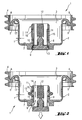
- the entire valve arrangement bears the reference number 1. It comprises a valve disk 2, the whole consists of a plastic, as it is shown in the figures by the corresponding Hatching is indicated.
- the valve disk 2 essentially has a cup-shaped Shape with a pot bottom 7 and a protruding pot wall 3.
- the Wall thickness t of the cup wall 3 of the valve plate 2 is approximately 0.2 mm to approximately 1 mm, preferably 0.3 mm to 0.8 mm.
- a central one Cut out opening 9 which projects through a cylindrical, projecting from the pot bottom 7 Piston guide 8 continues.
- Valve plate 2 made of plastic is equipped with a discharge valve 11, which is a valve piston 12 with a sealing body 13 and a restoring element 15.
- the sealing body 13 is provided with elastic slats, which in the closed state of the Discharge valve 11 sealingly rest on valve seat 10 (Fig. 1).
- the reset element 15 is formed as an annular spring element which between the piston guide 8 and a circumferential shoulder 16 provided on the valve stem 12 is held.
- the valve stem 12 has at least one flow channel 14, which in the open state of the Discharge valve 11 (Fig. 2) together with the central opening 9 of the valve plate Forms an outlet opening for the medium kept under pressure in the pressure cell. How 2, the reset element 15 has a radial Resilience, which is expressed in that the annular spring body 15 when actuated of the discharge valve 11 is radially elastically bendable.
- An external threaded ring 4 forms a coupling device for the can adapter of a dispenser and is thin Connecting webs 5 connected to the peripheral edge of the cup-shaped valve plate 2.
- the connecting webs 5 are equipped with predetermined breaking points 6 indicated by dashed lines, that break when a maximum permissible torque or tilting torque is exceeded.
- Fig. 3 shows the valve assembly of Fig. 1 and 2 in the assembled state.
- the Valve plate 2 is positively connected to the opening edge 21 of the pressure cell 22, especially clinched.
- the circumferential bead created by the clinching is included provided with the reference numeral 23.
- the sealing lip 17 is a pressure-assisted sealing element formed, and amplified by the pressure of the inside the can 22nd stored medium its sealing effect.
- To stiffen the valve plate 2 is one cylindrical stiffening sleeve 18 is provided, which is inserted into the valve plate 2 and is positively connected to the pressure cell 22 together with the valve plate 2.
- the Stiffening sleeve 18 has a bottom section 20 with a central recess, through which the discharge valve 11 is guided, and a cylindrical wall 19 which on the Pot wall 3 of the valve plate 2 abuts. With this arrangement, the valve plate 2 supported both in the bottom area 7 and in the area of the pot wall 3.
- the Stiffening sleeve 18 is a simple deep-drawn part made of sheet metal and has, for example a wall thickness of about 0.2 to about 0.5 mm.
Landscapes
- Chemical & Material Sciences (AREA)
- Dispersion Chemistry (AREA)
- Engineering & Computer Science (AREA)
- Mechanical Engineering (AREA)
- Containers And Packaging Bodies Having A Special Means To Remove Contents (AREA)
Applications Claiming Priority (2)
| Application Number | Priority Date | Filing Date | Title |
|---|---|---|---|
| DE19937283A DE19937283A1 (de) | 1999-08-06 | 1999-08-06 | Ventilanordnung zur Abgabe von in Behältnissen unter Druck gelagerten fluiden Medien |
| DE19937283 | 1999-08-06 |
Publications (2)
| Publication Number | Publication Date |
|---|---|
| EP1074484A1 true EP1074484A1 (fr) | 2001-02-07 |
| EP1074484B1 EP1074484B1 (fr) | 2004-05-19 |
Family
ID=7917534
Family Applications (1)
| Application Number | Title | Priority Date | Filing Date |
|---|---|---|---|
| EP00810673A Expired - Lifetime EP1074484B1 (fr) | 1999-08-06 | 2000-07-27 | Agencement de soupape pour récipient distributeur de fluides stockés sous pression |
Country Status (3)
| Country | Link |
|---|---|
| US (1) | US6371338B1 (fr) |
| EP (1) | EP1074484B1 (fr) |
| DE (2) | DE19937283A1 (fr) |
Cited By (2)
| Publication number | Priority date | Publication date | Assignee | Title |
|---|---|---|---|---|
| EP2028131A3 (fr) * | 2007-08-24 | 2010-05-26 | Werner, Hans Jürgen | Soupape en matière solide |
| EP2287088A1 (fr) | 2009-08-19 | 2011-02-23 | Altachem Holdings NV | Valve avec propulsion de sécurité |
Families Citing this family (25)
| Publication number | Priority date | Publication date | Assignee | Title |
|---|---|---|---|---|
| US6523860B1 (en) | 2000-10-12 | 2003-02-25 | Illinois Tool Works Inc. | Fuel cell adapter system for combustion tools |
| US6796478B2 (en) | 2000-10-12 | 2004-09-28 | Illinois Tool Works Inc. | Fuel cell adapter system for combustion tools |
| DE20116336U1 (de) | 2001-10-05 | 2001-12-06 | Aerosol-Technik LINDAL GmbH, 23843 Bad Oldesloe | Ventilanordnung für einen unter Druck stehenden Fluidbehälter |
| US6786378B2 (en) | 2002-01-09 | 2004-09-07 | Illinois Tool Works Inc. | Fastener tool having auxiliary fuel cell metering valve stem seal adaptor |
| EP1485309B1 (fr) * | 2002-01-24 | 2009-11-18 | Rathor Ag | Soupape |
| US20060138178A1 (en) * | 2002-10-31 | 2006-06-29 | Scheindel Christian T | Axially actuated valve for dispensing pressurized product |
| US8210400B2 (en) * | 2002-10-31 | 2012-07-03 | Christian T. Scheindel | Valve for use in a container which employs pressure to dispense product |
| US6938810B2 (en) | 2003-04-15 | 2005-09-06 | Illinois Tool Works Inc. | Fuel cell adapter system for combustion tools |
| US7261225B2 (en) * | 2004-10-04 | 2007-08-28 | Clayton Corporation | Valve for aerosol can |
| DE102008051888B4 (de) * | 2008-10-16 | 2011-02-03 | C. Ehrensperger Ag | Ventil für einen Behälter zur Abgabe von unter Druck stehendem Fluid |
| US8245888B2 (en) * | 2008-10-24 | 2012-08-21 | S.C. Johnson & Son, Inc. | Barrier piston with seal |
| DE102011082911A1 (de) * | 2011-09-19 | 2013-03-21 | Hilti Aktiengesellschaft | Brandschutzelement |
| USD794781S1 (en) * | 2015-04-13 | 2017-08-15 | Medela Holding Ag | Valve component for a breastmilk collection system |
| USD812101S1 (en) | 2016-05-27 | 2018-03-06 | Illinois Tool Works Inc. | Combination fuel cell adapter and cap |
| US10598377B2 (en) | 2016-05-27 | 2020-03-24 | Illinois Tool Works Inc. | Combustion-powered fastener driving tool fuel cell assembly |
| USD831201S1 (en) | 2016-08-29 | 2018-10-16 | Medela Holding Ag | Safety valve component for a breastmilk collection system |
| US10501258B2 (en) | 2017-05-26 | 2019-12-10 | The Procter & Gamble Company | Aerosol dispenser having annular seals and aerosol container therefor |
| US20180339841A1 (en) * | 2017-05-26 | 2018-11-29 | The Procter & Gamble Company | Sheath to protect an aerosol valve stem |
| US10557738B2 (en) | 2017-09-11 | 2020-02-11 | Black & Decker Inc. | External fuel metering valve with shuttle mechanism |
| BE1025177B1 (nl) * | 2017-09-21 | 2018-11-29 | Altachem Nv | Klep voor een houder |
| DE202020000677U1 (de) * | 2019-02-27 | 2020-03-20 | Aptar Dortmund Gmbh | Ventil und Abgabevorrichtung |
| US11978915B2 (en) | 2020-09-01 | 2024-05-07 | Illinois Tool Works Inc. | Combustion-powered fastener driving tool fuel cell adapter |
| USD1001736S1 (en) | 2020-09-01 | 2023-10-17 | Illinois Tool Works Inc. | Fuel cell adapter for tool |
| US11992925B2 (en) | 2021-11-23 | 2024-05-28 | Illinois Tool Works Inc. | Fuel cell adapter for fastener driving tool |
| EP4345027A1 (fr) * | 2022-09-29 | 2024-04-03 | iSi GmbH | Soupape de prélèvement et de dosage pour un dispositif de distribution de produits pulvérisés |
Citations (5)
| Publication number | Priority date | Publication date | Assignee | Title |
|---|---|---|---|---|
| US3817297A (en) * | 1971-08-20 | 1974-06-18 | H King | Reusable aerosol dispenser |
| GB1505530A (en) * | 1974-06-14 | 1978-03-30 | Aerosol Inventions Dev | Valves for pressurised dispensers |
| GB2096245A (en) * | 1981-04-07 | 1982-10-13 | Coster Tecnologie Speciali Spa | A dispensing device for pastes, creams and thick liquids |
| US4522318A (en) * | 1980-12-19 | 1985-06-11 | Luigi Del Bon | Discharge valve for use in a pressurized container |
| US4852807A (en) * | 1988-03-28 | 1989-08-01 | Stoody William R | Neoteric simplified aerosol valve |
Family Cites Families (4)
| Publication number | Priority date | Publication date | Assignee | Title |
|---|---|---|---|---|
| FR2508136B1 (fr) * | 1981-06-19 | 1985-12-06 | Oreal | Perfectionnement aux valves pour recipients aerosols |
| JPH0335399Y2 (fr) * | 1985-11-08 | 1991-07-26 | ||
| FR2636314B1 (fr) * | 1988-09-12 | 1990-11-16 | Oreal | Dispositif de fixation d'une valve sur un recipient pressurise et recipient equipe d'un tel dispositif |
| FR2777967B1 (fr) * | 1998-04-28 | 2000-06-16 | Oreal | Organe d'activation d'une valve,valve equipee de cet organe et ensemble de distribution muni de cette valve |
-
1999
- 1999-08-06 DE DE19937283A patent/DE19937283A1/de not_active Withdrawn
-
2000
- 2000-07-19 US US09/618,874 patent/US6371338B1/en not_active Expired - Lifetime
- 2000-07-27 DE DE50006463T patent/DE50006463D1/de not_active Expired - Fee Related
- 2000-07-27 EP EP00810673A patent/EP1074484B1/fr not_active Expired - Lifetime
Patent Citations (5)
| Publication number | Priority date | Publication date | Assignee | Title |
|---|---|---|---|---|
| US3817297A (en) * | 1971-08-20 | 1974-06-18 | H King | Reusable aerosol dispenser |
| GB1505530A (en) * | 1974-06-14 | 1978-03-30 | Aerosol Inventions Dev | Valves for pressurised dispensers |
| US4522318A (en) * | 1980-12-19 | 1985-06-11 | Luigi Del Bon | Discharge valve for use in a pressurized container |
| GB2096245A (en) * | 1981-04-07 | 1982-10-13 | Coster Tecnologie Speciali Spa | A dispensing device for pastes, creams and thick liquids |
| US4852807A (en) * | 1988-03-28 | 1989-08-01 | Stoody William R | Neoteric simplified aerosol valve |
Cited By (5)
| Publication number | Priority date | Publication date | Assignee | Title |
|---|---|---|---|---|
| EP2028131A3 (fr) * | 2007-08-24 | 2010-05-26 | Werner, Hans Jürgen | Soupape en matière solide |
| EP2287088A1 (fr) | 2009-08-19 | 2011-02-23 | Altachem Holdings NV | Valve avec propulsion de sécurité |
| WO2011020864A1 (fr) | 2009-08-19 | 2011-02-24 | Altachem Holding Nv | Valve ayant une partie saillante de sécurité |
| CN102574628A (zh) * | 2009-08-19 | 2012-07-11 | 艾尔塔彻姆控股公司 | 具有安全突出部的阀 |
| US20130200111A1 (en) * | 2009-08-19 | 2013-08-08 | Faigle Kunststoffe Gmbh | Valve with safety protrusion |
Also Published As
| Publication number | Publication date |
|---|---|
| DE19937283A1 (de) | 2001-02-15 |
| EP1074484B1 (fr) | 2004-05-19 |
| US6371338B1 (en) | 2002-04-16 |
| DE50006463D1 (de) | 2004-06-24 |
Similar Documents
| Publication | Publication Date | Title |
|---|---|---|
| EP1074484B1 (fr) | Agencement de soupape pour récipient distributeur de fluides stockés sous pression | |
| DE69024668T2 (de) | Abgabevorrichtung für wenigstens ein flüssiges Produkt, insbesondere kosmetischer oder pharmazeutischer Art | |
| EP2247711B1 (fr) | Bioréacteur | |
| DE1946734U (de) | Filter fuer stroemende medien, insbesondere oelfilter. | |
| EP3324084A1 (fr) | Soupape à membrane | |
| DE1057289B (de) | Zerstaeuber fuer in einem aus Glas bestehenden Behaelter unter Druck gehaltene Stoffe, insbesondere Fluessigkeiten | |
| EP0550503A1 (fr) | Reservoir sous pression a jeter, servant en particulier de recharge pour les installations frigorifiques et les installations de climatisation. | |
| EP3382239B1 (fr) | Systeme de récipient verrouillable | |
| EP0367287B1 (fr) | Vanne à diaphragme avec une membrane élastique supportée par le couvercle de vanne | |
| EP0654010A1 (fr) | Soupape d'arret en matiere plastique. | |
| DE1600910A1 (de) | Fluessigkeitsventil | |
| EP3366961B1 (fr) | Clapet à membrane à passage libre | |
| WO1997015771A1 (fr) | Electrovanne avec induit de levee | |
| EP1036261B1 (fr) | Couvercle de fermeture | |
| DE602004006457T2 (de) | Ventilanordnung | |
| EP0696545A1 (fr) | Valve pour la distribution de fluides sous pression | |
| EP0921299B1 (fr) | Dispositif pour l'étanchéification d'un dispositif de pompage de carburant dans un réservoir de carburant | |
| DE2217028A1 (de) | Ventilaufbau | |
| EP1678413A1 (fr) | Bouchon de radiateur de vehicule | |
| DE2435328C3 (de) | Heizkörperverschraubung | |
| EP1549867B1 (fr) | Vanne de vidange par le bas con ue en particulier pour des recipients emailles | |
| EP1523613B1 (fr) | Bouchon de fermeture | |
| WO1999066250A1 (fr) | Soupape avec bague a aretes d'etancheite | |
| DE7305218U (de) | Ventil | |
| WO2002076626A1 (fr) | Dispositif de distribution pour fluides |
Legal Events
| Date | Code | Title | Description |
|---|---|---|---|
| PUAI | Public reference made under article 153(3) epc to a published international application that has entered the european phase |
Free format text: ORIGINAL CODE: 0009012 |
|
| AK | Designated contracting states |
Kind code of ref document: A1 Designated state(s): DE FR GB |
|
| AX | Request for extension of the european patent |
Free format text: AL;LT;LV;MK;RO;SI |
|
| 17P | Request for examination filed |
Effective date: 20010807 |
|
| AKX | Designation fees paid |
Free format text: DE FR GB |
|
| GRAP | Despatch of communication of intention to grant a patent |
Free format text: ORIGINAL CODE: EPIDOSNIGR1 |
|
| GRAS | Grant fee paid |
Free format text: ORIGINAL CODE: EPIDOSNIGR3 |
|
| GRAA | (expected) grant |
Free format text: ORIGINAL CODE: 0009210 |
|
| AK | Designated contracting states |
Kind code of ref document: B1 Designated state(s): DE FR GB |
|
| REG | Reference to a national code |
Ref country code: GB Ref legal event code: FG4D Free format text: NOT ENGLISH |
|
| REF | Corresponds to: |
Ref document number: 50006463 Country of ref document: DE Date of ref document: 20040624 Kind code of ref document: P |
|
| GBT | Gb: translation of ep patent filed (gb section 77(6)(a)/1977) |
Effective date: 20040802 |
|
| ET | Fr: translation filed | ||
| PLBE | No opposition filed within time limit |
Free format text: ORIGINAL CODE: 0009261 |
|
| STAA | Information on the status of an ep patent application or granted ep patent |
Free format text: STATUS: NO OPPOSITION FILED WITHIN TIME LIMIT |
|
| 26N | No opposition filed |
Effective date: 20050222 |
|
| PGFP | Annual fee paid to national office [announced via postgrant information from national office to epo] |
Ref country code: DE Payment date: 20070705 Year of fee payment: 8 |
|
| PGFP | Annual fee paid to national office [announced via postgrant information from national office to epo] |
Ref country code: GB Payment date: 20070725 Year of fee payment: 8 |
|
| PGFP | Annual fee paid to national office [announced via postgrant information from national office to epo] |
Ref country code: FR Payment date: 20070710 Year of fee payment: 8 |
|
| GBPC | Gb: european patent ceased through non-payment of renewal fee |
Effective date: 20080727 |
|
| PG25 | Lapsed in a contracting state [announced via postgrant information from national office to epo] |
Ref country code: DE Free format text: LAPSE BECAUSE OF NON-PAYMENT OF DUE FEES Effective date: 20090203 |
|
| REG | Reference to a national code |
Ref country code: FR Ref legal event code: ST Effective date: 20090331 |
|
| PG25 | Lapsed in a contracting state [announced via postgrant information from national office to epo] |
Ref country code: GB Free format text: LAPSE BECAUSE OF NON-PAYMENT OF DUE FEES Effective date: 20080727 |
|
| PG25 | Lapsed in a contracting state [announced via postgrant information from national office to epo] |
Ref country code: FR Free format text: LAPSE BECAUSE OF NON-PAYMENT OF DUE FEES Effective date: 20080731 |