EP1074679A2 - Vorrichtung zum Spülen eines Schwimmbeckenbodens - Google Patents
Vorrichtung zum Spülen eines Schwimmbeckenbodens Download PDFInfo
- Publication number
- EP1074679A2 EP1074679A2 EP00500118A EP00500118A EP1074679A2 EP 1074679 A2 EP1074679 A2 EP 1074679A2 EP 00500118 A EP00500118 A EP 00500118A EP 00500118 A EP00500118 A EP 00500118A EP 1074679 A2 EP1074679 A2 EP 1074679A2
- Authority
- EP
- European Patent Office
- Prior art keywords
- tubular body
- swimming pool
- nozzle
- tubular
- pool bottom
- Prior art date
- Legal status (The legal status is an assumption and is not a legal conclusion. Google has not performed a legal analysis and makes no representation as to the accuracy of the status listed.)
- Granted
Links
- 230000009182 swimming Effects 0.000 title claims abstract description 42
- 238000011010 flushing procedure Methods 0.000 title claims abstract description 17
- XLYOFNOQVPJJNP-UHFFFAOYSA-N water Substances O XLYOFNOQVPJJNP-UHFFFAOYSA-N 0.000 claims abstract description 22
- 230000002093 peripheral effect Effects 0.000 claims description 5
- 230000008878 coupling Effects 0.000 claims description 4
- 238000010168 coupling process Methods 0.000 claims description 4
- 238000005859 coupling reaction Methods 0.000 claims description 4
- 230000000717 retained effect Effects 0.000 claims description 3
- 238000007789 sealing Methods 0.000 claims description 3
- 230000014759 maintenance of location Effects 0.000 claims description 2
- 238000009434 installation Methods 0.000 description 2
- 239000000463 material Substances 0.000 description 2
- 229920003023 plastic Polymers 0.000 description 2
- 239000004033 plastic Substances 0.000 description 2
- 229910052572 stoneware Inorganic materials 0.000 description 2
- 206010036872 Prolonged labour Diseases 0.000 description 1
- 238000004026 adhesive bonding Methods 0.000 description 1
- 238000010276 construction Methods 0.000 description 1
- 239000003292 glue Substances 0.000 description 1
- 238000000034 method Methods 0.000 description 1
Images


Classifications
-
- E—FIXED CONSTRUCTIONS
- E04—BUILDING
- E04H—BUILDINGS OR LIKE STRUCTURES FOR PARTICULAR PURPOSES; SWIMMING OR SPLASH BATHS OR POOLS; MASTS; FENCING; TENTS OR CANOPIES, IN GENERAL
- E04H4/00—Swimming or splash baths or pools
- E04H4/14—Parts, details or accessories not otherwise provided for
- E04H4/16—Parts, details or accessories not otherwise provided for specially adapted for cleaning
- E04H4/169—Pool nozzles
Definitions
- the present invention relates to a swimming pool bottom flushing device.
- This device is of the type comprising a tubular supporting arrangement glued to the PVC pipe arranged at the swimming pool bottom, and a nozzle axially fitted into said supporting arrangement in a freely rotatable, vertically shiftable arrangement, said nozzle laterally having at least one orifice through which water is ejected to flush the swimming pool bottom, means being provided between the supporting arrangement and the nozzle to determine the intermittent, partial rotation of the nozzle.
- This device does for such a purpose comprise a supporting arrangement formed by a ball-bushing fitted into a socket attached to the water delivery pipe, said nozzle being fitted into said ball-bushing.
- the nozzle will always be fitted at right angles to said bottom even if said pipe is finally laid in an inclined arrangement with respect to the swimming pool bottom.
- the socket attached to the pipe has on its inner surface alternate, longitudinal protrusions of which some have a concave profile in the vicinity of one of the socket's openings, whereas the other protrusions have said concave profile in the vicinity of the opposite one of both socket's openings, the ball-bushing being fitted between said protrusions and externally having an all-around flange fitting on the open top of the water delivery pipe and on the surfacing of the swimming pool bottom.
- the nozzle comprises a fitted-in upper, tubular plug arranged as per a rotationally positionable arrangement and laterally having openings of different diameters provided to selectively face at least one opening of the nozzle's tubular body in order to control the flow rate and pressure of the water jet ejected for the flushing of the swimming pool bottom.
- tubular body of the nozzle allows to indifferently fit it, through the use of corresponding means, with a spring or a weight provided to urge said tubular body downwards in its vertically shifting motion.
- Said tubular body is inserted into a bushing fitted into the tubular supporting arrangement supporting the nozzle, said tubular body on its periphery having lugs extending between alternate projections projecting as per an inclined plane from the inner periphery of said bushing in order to thus obtain its intermittent rotation as it shifts vertically.
- a safety element has been provided in order to disengageably engage the top plug with the tubular body of the nozzle.
- This de vice is in a practical and safe way arranged for the attachment of the swimming pool bottom surfacing in those cases having for such a surfacing a sheet for example of plastics material.
- the tubular supporting arrangement comprises at its open top a collar exteriorly extending into a peripheral flange having embedded in it several nuts each of them threadingly engaging a respective screw clamping a ring on said flange for the retention of the swimming pool bottom surfacing sheet between said ring and flange, said sheet being for such a purpose provided with the corresponding openings.
- the surfacing sheet is applied on a sealing washer placed on the flange of the tubular supporting arrangement and provided with orifices for the passage of said screws.
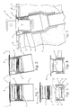
- the swimming pool bottom flushing device comprises a tubular supporting arrangement 1 attached to the bottom F of a swimming pool, and a nozzle 2 with at least one lateral opening provided to eject the water, said nozzle being axially fitted into said supporting arrangement in a freely rotatable, vertically shiftable arrangement.
- Said supporting arrangement 1 comprises a socket 3 having a cylindrical outer surface through which it is attached by means of glue to the inside of the water delivery pipe 4, said socket having on its inner surface longitudinal protrusions 5 and 5' arranged as per an alternate arrangement two by two, of which the former have a concave profile 6 in the vicinity of the open top of socket 3, whereas protrusions 5' have their concave profile 6' in the vicinity of the open bottom of said socket, a ball-bushing 7 being fitted between said protrusions and at its upper end forming an all-around flange 8 fitting on the open top of pipe 4 and on the surfacing of the swimming pool bottom F.
- Fig. 3 is shown how to arrange ball-bushing 7 in order to fit it into socket 3.
- the former is arranged in a coaxial arrangement as regards the latter, and is pressed in thus causing the top lips of protrusions 5' to resiliently yield due to their thinness.
- Fig. 5 By Fig. 5 can be seen how in spite of the inclined arrangement of pipe 4 ball-bushing 7 allows to properly arrange the tiles on swimming pool bottom F, said tiles in this case being stoneware tiles B or the like.
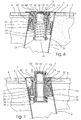
- the nozzle is comprised of an open-ended tubular body 13 provided with at least one opening 14 in the upper region of its periphery, said nozzle being fitted at its open top 15 with a tubular, rotationally positionable plug 16 peripherally provided with two openings 17 and 17' of different diameters provided to selectively face the opening 14 of the tubular body in order to control the outflow of the water jet ejected for the flushing of the swimming pool bottom F, this latter being in this case flagged with stoneware tiles B or the like.
- Tubular body 13 is freely fitted into a bushing 20 fitted through bayonet coupling by means of four equispaced lugs 21 into the tubular supporting arrangement 1 provided to support the nozzle, said tubular body on its outer periphery also comprising four equispaced lugs 22 extending between alternate projections 23 projecting as per an inclined plane (Fig. 10) from the inner periphery of said bushing in order to thus obtain its intermittent rotation as it is vertically shifted upwards as per arrow D (Fig. 7) by virtue of the water pressure.
- a bushing 20 fitted through bayonet coupling by means of four equispaced lugs 21 into the tubular supporting arrangement 1 provided to support the nozzle, said tubular body on its outer periphery also comprising four equispaced lugs 22 extending between alternate projections 23 projecting as per an inclined plane (Fig. 10) from the inner periphery of said bushing in order to thus obtain its intermittent rotation as it is vertically shifted upwards as per arrow D (Fig
- tubular body 13 When the water pressure lessens the downward vertical shifting motion of tubular body 13 is indifferently achieved by means of a spring 24 (Figs. 6 and 8) or by means of a weight 25 (Figs. 7 and 9).
- Spring 24 is arranged around said tubular body and between a peripheral flange 26 of the open bottom 27 of said body and a step 28 of the inner periphery of bushing 20 (Fig. 10).
- Weight 25 is tubular and is inserted into tubular body 13 thereby being inferiorly retained by means of a ring 29 fitted through bayonet coupling at 30 to the open bottom 27 of said tubular body, said ring for such a purpose having two opposed lugs 31 (Fig. 9).
- a seal 32 is arranged on top of flange 26 of tubular body 13.
- a safety element has been provided to engage said plug with said body, said safety element consisting in a resilient, split annular piece 16' tangentially extending into a stub 16".
- This annular piece is arranged inside plug 16 next to its top bottom thereby passing stub 16" through a lateral orifice 17" of said plug, said stub thus projecting from said orifice to thereby fit into one of the four notches 13' provided at the open top 15 of tubular body 13 (Fig. 8).
- the tubular supporting arrangement 1 will comprise a socket 3 and a bushing 7 forming a ball-and-socket joint in order to obtain the upward shifting motion of the nozzle's tubular body 13 at right angles with respect to the swimming pool bottom.
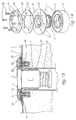
- this swimming pool bottom flushing device comprises a tubular supporting arrangement 1' and 1" attached to the bottom F of a swimming pool, and a nozzle 2 with at least one lateral opening for ejecting the water, said nozzle being axially fitted into said tubular supporting arrangement in a freely rotatable, vertically shiftable arrangement.
- Tubular supporting arrangement 1' and 1" at its open top comprises a collar 33 exteriorly extending into a peripheral flange 8' having equispacedly embedded in it six nuts 34 each threadingly engaging a respective taper-headed screw 35 clamping a ring 36 on said flange 8', said ring being for such a purpose provided with respective countersunk orifices 37, the sheet L of plastics material to be used to cover the swimming pool bottom F being thus retained between said ring and flange, said sheet for such a purpose having the corresponding openings A.
- Said surfacing sheet L will be advantageously applied on a sealing washer 38 placed on flange 8' of tubular supporting arrangement 1', 1", said washer being provided with the corresponding orifices 39 for the passage of said screws 35.
- Tubular supporting arrangement 1' (Figs. 11, 12 and 14) consists of a ball-bushing 7' fitted into a socket 3' glued to the inside of pipe 4', this providing a shifting motion of nozzle 2 at right angles with respect to the swimming pool bottom even if pipe 4' is arranged in an inclined arrangement (Fig. 12).
- Socket 3' comprises an outer, concentric bushing 3" provided to increase its diameter to thus adapt it to the diameter of pipe 4' to which said socket is to be attached.
- This outer bushing 3" can form a one-piece structure with socket 3', or it can consist of an independent piece suitably fitted to said inner socket.
- Tubular supporting arrangement 1" (Fig. 13) is formed by a bushing 3"' provided to be directly glued to pipe 4" since in this case the presence of a ball-and-socket joint is not necessary as said pipe is arranged in a perpendicular arrangement with respect to the swimming pool bottom F.
Landscapes
- Engineering & Computer Science (AREA)
- Architecture (AREA)
- Civil Engineering (AREA)
- Structural Engineering (AREA)
- Cleaning By Liquid Or Steam (AREA)
- Cleaning In General (AREA)
- Special Spraying Apparatus (AREA)
- Devices For Medical Bathing And Washing (AREA)
- Vehicle Cleaning, Maintenance, Repair, Refitting, And Outriggers (AREA)
- Treatment Of Fiber Materials (AREA)
- Nozzles (AREA)
- Detergent Compositions (AREA)
Applications Claiming Priority (6)
| Application Number | Priority Date | Filing Date | Title |
|---|---|---|---|
| ES009902085U ES1044076Y (es) | 1999-08-04 | 1999-08-04 | Dispositivo para la limpieza de fondos de piscinas. |
| ES9902085U | 1999-08-04 | ||
| ES009902095U ES1044084Y (es) | 1999-08-05 | 1999-08-05 | Dispositivo para la limpieza de fondos de piscinas. |
| ES9902095U | 1999-08-05 | ||
| ES9902108U ES1044095Y (es) | 1999-08-06 | 1999-08-06 | Dispositivo para la limpieza de fondos de piscinas. |
| ES9902108U | 1999-08-06 |
Publications (3)
| Publication Number | Publication Date |
|---|---|
| EP1074679A2 true EP1074679A2 (de) | 2001-02-07 |
| EP1074679A3 EP1074679A3 (de) | 2002-05-29 |
| EP1074679B1 EP1074679B1 (de) | 2003-10-01 |
Family
ID=27240582
Family Applications (1)
| Application Number | Title | Priority Date | Filing Date |
|---|---|---|---|
| EP00500118A Expired - Lifetime EP1074679B1 (de) | 1999-08-04 | 2000-06-07 | Vorrichtung zum Spülen eines Schwimmbeckenbodens |
Country Status (5)
| Country | Link |
|---|---|
| EP (1) | EP1074679B1 (de) |
| AT (1) | ATE251264T1 (de) |
| DE (1) | DE60005616T2 (de) |
| ES (1) | ES2209794T3 (de) |
| PT (1) | PT1074679E (de) |
Cited By (2)
| Publication number | Priority date | Publication date | Assignee | Title |
|---|---|---|---|---|
| FR2964402A1 (fr) * | 2010-09-08 | 2012-03-09 | Acp Agencement Et Creation De Piscines | Element de traversee d'une paroi formant l'enceinte d'une piscine batie |
| US20150176296A1 (en) * | 2013-10-08 | 2015-06-25 | James Mulhern | Angled Pool Jet Fitting |
Families Citing this family (2)
| Publication number | Priority date | Publication date | Assignee | Title |
|---|---|---|---|---|
| DE102023109130A1 (de) * | 2023-04-12 | 2024-10-17 | Mts Produkte Für Den Schwimmbadbau Und Die Unterwassertechnik Gmbh | Einbauteil für ein Wasserbecken |
| WO2025120564A1 (en) * | 2023-12-06 | 2025-06-12 | Gerit S.R.L. | Bottom nozzle for pool and/or fountain |
Family Cites Families (2)
| Publication number | Priority date | Publication date | Assignee | Title |
|---|---|---|---|---|
| US4371994A (en) * | 1980-06-02 | 1983-02-08 | Lester R. Mathews | Rotational indexing nozzle arrangement |
| US6138293A (en) * | 1999-06-14 | 2000-10-31 | Caretaker Systems, Inc. | Adjustable mounting collar for a retractable cleaning head |
-
2000
- 2000-06-07 AT AT00500118T patent/ATE251264T1/de not_active IP Right Cessation
- 2000-06-07 DE DE60005616T patent/DE60005616T2/de not_active Expired - Fee Related
- 2000-06-07 EP EP00500118A patent/EP1074679B1/de not_active Expired - Lifetime
- 2000-06-07 ES ES00500118T patent/ES2209794T3/es not_active Expired - Lifetime
- 2000-06-07 PT PT00500118T patent/PT1074679E/pt unknown
Cited By (4)
| Publication number | Priority date | Publication date | Assignee | Title |
|---|---|---|---|---|
| FR2964402A1 (fr) * | 2010-09-08 | 2012-03-09 | Acp Agencement Et Creation De Piscines | Element de traversee d'une paroi formant l'enceinte d'une piscine batie |
| US20150176296A1 (en) * | 2013-10-08 | 2015-06-25 | James Mulhern | Angled Pool Jet Fitting |
| US9809988B2 (en) * | 2013-10-08 | 2017-11-07 | Eco-Blu Pool Components Llc | Angled pool jet fitting |
| AU2014240361B2 (en) * | 2013-10-08 | 2018-08-16 | Eco-Blu Pool Components Llc | Angled pool jet fitting |
Also Published As
| Publication number | Publication date |
|---|---|
| DE60005616D1 (de) | 2003-11-06 |
| ATE251264T1 (de) | 2003-10-15 |
| EP1074679A3 (de) | 2002-05-29 |
| PT1074679E (pt) | 2003-12-31 |
| DE60005616T2 (de) | 2004-08-05 |
| ES2209794T3 (es) | 2004-07-01 |
| EP1074679B1 (de) | 2003-10-01 |
Similar Documents
| Publication | Publication Date | Title |
|---|---|---|
| US6438766B1 (en) | Swimming pool bottom flushing device | |
| CA2266952C (en) | Adjustable fill valve assembly | |
| CA1079452A (en) | Float and check valve for hydrotherapy unit air intake | |
| US3318528A (en) | Fountain | |
| US8636899B2 (en) | Vented alarm apparatus for use with a pool skimmer basket | |
| ES2387138T3 (es) | Unidad de salida de agua residual | |
| US4586532A (en) | Liquid level actuator | |
| EP1074679B1 (de) | Vorrichtung zum Spülen eines Schwimmbeckenbodens | |
| US4574405A (en) | Water level control device | |
| WO2019196350A1 (zh) | 净水器 | |
| US5329648A (en) | Diverter valve manipulator tool | |
| US6367097B1 (en) | Swimming pool bottom flushing device | |
| CN117051931B (zh) | 一种马桶底托安装结构及马桶 | |
| CN211165956U (zh) | 墨盒组件、墨盒部件及打印机 | |
| US3584642A (en) | Float controlled valve assembly | |
| US4438537A (en) | Liquid directional flow apparatus | |
| US4030148A (en) | Swimming pool surface cleaning device | |
| KR101124241B1 (ko) | 캡 구동용 툴의 가이드 장치를 구비한 상수도 맨홀 | |
| SU1293289A1 (ru) | Запорно-выпускное устройство дл смывного бачка | |
| CN214833153U (zh) | 一种可伸缩的花洒座 | |
| CN211165955U (zh) | 墨盒部件及打印机 | |
| JP3514112B2 (ja) | 洗浄水タンクにおける手洗吐水管の接続構造 | |
| KR20160042579A (ko) | 바닥분수용 노즐 장치 | |
| JP2543540Y2 (ja) | 排水桝の掃除口装置 | |
| KR200213228Y1 (ko) | 급수장치 |
Legal Events
| Date | Code | Title | Description |
|---|---|---|---|
| PUAI | Public reference made under article 153(3) epc to a published international application that has entered the european phase |
Free format text: ORIGINAL CODE: 0009012 |
|
| AK | Designated contracting states |
Kind code of ref document: A2 Designated state(s): AT BE CH CY DE DK ES FI FR GB GR IE IT LI LU MC NL PT SE |
|
| AX | Request for extension of the european patent |
Free format text: AL;LT;LV;MK;RO;SI |
|
| PUAL | Search report despatched |
Free format text: ORIGINAL CODE: 0009013 |
|
| AK | Designated contracting states |
Kind code of ref document: A3 Designated state(s): AT BE CH CY DE DK ES FI FR GB GR IE IT LI LU MC NL PT SE |
|
| AX | Request for extension of the european patent |
Free format text: AL;LT;LV;MK;RO;SI |
|
| 17P | Request for examination filed |
Effective date: 20020917 |
|
| AKX | Designation fees paid |
Designated state(s): AT BE CH CY DE DK ES FI FR GB GR IE IT LI LU MC NL PT SE |
|
| GRAH | Despatch of communication of intention to grant a patent |
Free format text: ORIGINAL CODE: EPIDOS IGRA |
|
| GRAS | Grant fee paid |
Free format text: ORIGINAL CODE: EPIDOSNIGR3 |
|
| GRAA | (expected) grant |
Free format text: ORIGINAL CODE: 0009210 |
|
| AK | Designated contracting states |
Kind code of ref document: B1 Designated state(s): AT BE CH CY DE DK ES FI FR GB GR IE IT LI LU MC NL PT SE |
|
| PG25 | Lapsed in a contracting state [announced via postgrant information from national office to epo] |
Ref country code: BE Free format text: LAPSE BECAUSE OF FAILURE TO SUBMIT A TRANSLATION OF THE DESCRIPTION OR TO PAY THE FEE WITHIN THE PRESCRIBED TIME-LIMIT Effective date: 20031001 Ref country code: CH Free format text: LAPSE BECAUSE OF FAILURE TO SUBMIT A TRANSLATION OF THE DESCRIPTION OR TO PAY THE FEE WITHIN THE PRESCRIBED TIME-LIMIT Effective date: 20031001 Ref country code: FI Free format text: LAPSE BECAUSE OF FAILURE TO SUBMIT A TRANSLATION OF THE DESCRIPTION OR TO PAY THE FEE WITHIN THE PRESCRIBED TIME-LIMIT Effective date: 20031001 Ref country code: NL Free format text: LAPSE BECAUSE OF FAILURE TO SUBMIT A TRANSLATION OF THE DESCRIPTION OR TO PAY THE FEE WITHIN THE PRESCRIBED TIME-LIMIT Effective date: 20031001 Ref country code: CY Free format text: LAPSE BECAUSE OF FAILURE TO SUBMIT A TRANSLATION OF THE DESCRIPTION OR TO PAY THE FEE WITHIN THE PRESCRIBED TIME-LIMIT Effective date: 20031001 Ref country code: AT Free format text: LAPSE BECAUSE OF FAILURE TO SUBMIT A TRANSLATION OF THE DESCRIPTION OR TO PAY THE FEE WITHIN THE PRESCRIBED TIME-LIMIT Effective date: 20031001 Ref country code: LI Free format text: LAPSE BECAUSE OF FAILURE TO SUBMIT A TRANSLATION OF THE DESCRIPTION OR TO PAY THE FEE WITHIN THE PRESCRIBED TIME-LIMIT Effective date: 20031001 |
|
| REG | Reference to a national code |
Ref country code: GB Ref legal event code: FG4D |
|
| REG | Reference to a national code |
Ref country code: CH Ref legal event code: EP |
|
| REG | Reference to a national code |
Ref country code: IE Ref legal event code: FG4D |
|
| REF | Corresponds to: |
Ref document number: 60005616 Country of ref document: DE Date of ref document: 20031106 Kind code of ref document: P |
|
| PG25 | Lapsed in a contracting state [announced via postgrant information from national office to epo] |
Ref country code: DK Free format text: LAPSE BECAUSE OF FAILURE TO SUBMIT A TRANSLATION OF THE DESCRIPTION OR TO PAY THE FEE WITHIN THE PRESCRIBED TIME-LIMIT Effective date: 20040101 Ref country code: SE Free format text: LAPSE BECAUSE OF FAILURE TO SUBMIT A TRANSLATION OF THE DESCRIPTION OR TO PAY THE FEE WITHIN THE PRESCRIBED TIME-LIMIT Effective date: 20040101 Ref country code: GR Free format text: LAPSE BECAUSE OF FAILURE TO SUBMIT A TRANSLATION OF THE DESCRIPTION OR TO PAY THE FEE WITHIN THE PRESCRIBED TIME-LIMIT Effective date: 20040101 |
|
| NLV1 | Nl: lapsed or annulled due to failure to fulfill the requirements of art. 29p and 29m of the patents act | ||
| REG | Reference to a national code |
Ref country code: CH Ref legal event code: PL |
|
| PG25 | Lapsed in a contracting state [announced via postgrant information from national office to epo] |
Ref country code: IE Free format text: LAPSE BECAUSE OF NON-PAYMENT OF DUE FEES Effective date: 20040607 Ref country code: LU Free format text: LAPSE BECAUSE OF NON-PAYMENT OF DUE FEES Effective date: 20040607 |
|
| ET | Fr: translation filed | ||
| PG25 | Lapsed in a contracting state [announced via postgrant information from national office to epo] |
Ref country code: MC Free format text: LAPSE BECAUSE OF NON-PAYMENT OF DUE FEES Effective date: 20040630 |
|
| REG | Reference to a national code |
Ref country code: ES Ref legal event code: FG2A Ref document number: 2209794 Country of ref document: ES Kind code of ref document: T3 |
|
| PLBE | No opposition filed within time limit |
Free format text: ORIGINAL CODE: 0009261 |
|
| STAA | Information on the status of an ep patent application or granted ep patent |
Free format text: STATUS: NO OPPOSITION FILED WITHIN TIME LIMIT |
|
| 26N | No opposition filed |
Effective date: 20040702 |
|
| REG | Reference to a national code |
Ref country code: IE Ref legal event code: MM4A |
|
| PGFP | Annual fee paid to national office [announced via postgrant information from national office to epo] |
Ref country code: PT Payment date: 20050520 Year of fee payment: 6 |
|
| PGFP | Annual fee paid to national office [announced via postgrant information from national office to epo] |
Ref country code: GB Payment date: 20050607 Year of fee payment: 6 |
|
| PGFP | Annual fee paid to national office [announced via postgrant information from national office to epo] |
Ref country code: FR Payment date: 20050627 Year of fee payment: 6 |
|
| PGFP | Annual fee paid to national office [announced via postgrant information from national office to epo] |
Ref country code: DE Payment date: 20050831 Year of fee payment: 6 |
|
| PG25 | Lapsed in a contracting state [announced via postgrant information from national office to epo] |
Ref country code: GB Free format text: LAPSE BECAUSE OF NON-PAYMENT OF DUE FEES Effective date: 20060607 |
|
| PG25 | Lapsed in a contracting state [announced via postgrant information from national office to epo] |
Ref country code: PT Free format text: LAPSE BECAUSE OF NON-PAYMENT OF DUE FEES Effective date: 20061207 |
|
| PG25 | Lapsed in a contracting state [announced via postgrant information from national office to epo] |
Ref country code: DE Free format text: LAPSE BECAUSE OF NON-PAYMENT OF DUE FEES Effective date: 20070103 |
|
| REG | Reference to a national code |
Ref country code: PT Ref legal event code: MM4A Free format text: LAPSE DUE TO NON-PAYMENT OF FEES Effective date: 20061207 |
|
| GBPC | Gb: european patent ceased through non-payment of renewal fee |
Effective date: 20060607 |
|
| REG | Reference to a national code |
Ref country code: FR Ref legal event code: ST Effective date: 20070228 |
|
| PGFP | Annual fee paid to national office [announced via postgrant information from national office to epo] |
Ref country code: ES Payment date: 20070613 Year of fee payment: 8 |
|
| PG25 | Lapsed in a contracting state [announced via postgrant information from national office to epo] |
Ref country code: FR Free format text: LAPSE BECAUSE OF NON-PAYMENT OF DUE FEES Effective date: 20060630 |
|
| REG | Reference to a national code |
Ref country code: ES Ref legal event code: FD2A Effective date: 20080609 |
|
| PG25 | Lapsed in a contracting state [announced via postgrant information from national office to epo] |
Ref country code: ES Free format text: LAPSE BECAUSE OF NON-PAYMENT OF DUE FEES Effective date: 20080609 |
|
| PG25 | Lapsed in a contracting state [announced via postgrant information from national office to epo] |
Ref country code: IT Free format text: LAPSE BECAUSE OF NON-PAYMENT OF DUE FEES Effective date: 20110607 |
|
| PGFP | Annual fee paid to national office [announced via postgrant information from national office to epo] |
Ref country code: IT Payment date: 20111230 Year of fee payment: 12 |
|
| PG25 | Lapsed in a contracting state [announced via postgrant information from national office to epo] |
Ref country code: IT Free format text: LAPSE BECAUSE OF NON-PAYMENT OF DUE FEES Effective date: 20120607 |