EP1074683A1 - Verriegelungsvorrichtung für mindestens dreiflügelige Fenster und Türen - Google Patents
Verriegelungsvorrichtung für mindestens dreiflügelige Fenster und Türen Download PDFInfo
- Publication number
- EP1074683A1 EP1074683A1 EP00108881A EP00108881A EP1074683A1 EP 1074683 A1 EP1074683 A1 EP 1074683A1 EP 00108881 A EP00108881 A EP 00108881A EP 00108881 A EP00108881 A EP 00108881A EP 1074683 A1 EP1074683 A1 EP 1074683A1
- Authority
- EP
- European Patent Office
- Prior art keywords
- locking device
- wing
- slide
- bolt
- striker
- Prior art date
- Legal status (The legal status is an assumption and is not a legal conclusion. Google has not performed a legal analysis and makes no representation as to the accuracy of the status listed.)
- Withdrawn
Links
- 238000004146 energy storage Methods 0.000 claims description 20
- 239000000463 material Substances 0.000 claims description 9
- 230000008878 coupling Effects 0.000 claims description 7
- 238000010168 coupling process Methods 0.000 claims description 7
- 238000005859 coupling reaction Methods 0.000 claims description 7
- 230000006835 compression Effects 0.000 claims description 4
- 238000007906 compression Methods 0.000 claims description 4
- 239000004033 plastic Substances 0.000 claims description 4
- 238000002347 injection Methods 0.000 claims description 2
- 239000007924 injection Substances 0.000 claims description 2
- 230000000295 complement effect Effects 0.000 claims 1
- 230000009471 action Effects 0.000 abstract description 2
- 238000010009 beating Methods 0.000 abstract 1
- 230000008901 benefit Effects 0.000 description 5
- 238000013461 design Methods 0.000 description 5
- 238000004519 manufacturing process Methods 0.000 description 5
- 230000007246 mechanism Effects 0.000 description 5
- 230000002093 peripheral effect Effects 0.000 description 4
- 238000009434 installation Methods 0.000 description 3
- 238000000034 method Methods 0.000 description 3
- 230000003287 optical effect Effects 0.000 description 3
- 230000008569 process Effects 0.000 description 3
- 230000006735 deficit Effects 0.000 description 2
- 238000007789 sealing Methods 0.000 description 2
- 125000006850 spacer group Chemical group 0.000 description 2
- 238000012549 training Methods 0.000 description 2
- 240000007817 Olea europaea Species 0.000 description 1
- 230000002411 adverse Effects 0.000 description 1
- 238000005266 casting Methods 0.000 description 1
- 230000008859 change Effects 0.000 description 1
- 238000010276 construction Methods 0.000 description 1
- 238000011161 development Methods 0.000 description 1
- 230000000694 effects Effects 0.000 description 1
- 238000009963 fulling Methods 0.000 description 1
- 210000003128 head Anatomy 0.000 description 1
- 239000002991 molded plastic Substances 0.000 description 1
- 210000002346 musculoskeletal system Anatomy 0.000 description 1
- 238000003825 pressing Methods 0.000 description 1
- 238000012545 processing Methods 0.000 description 1
- 238000003860 storage Methods 0.000 description 1
- 238000009423 ventilation Methods 0.000 description 1
Images



Classifications
-
- E—FIXED CONSTRUCTIONS
- E05—LOCKS; KEYS; WINDOW OR DOOR FITTINGS; SAFES
- E05C—BOLTS OR FASTENING DEVICES FOR WINGS, SPECIALLY FOR DOORS OR WINDOWS
- E05C7/00—Fastening devices specially adapted for two wings
- E05C7/04—Fastening devices specially adapted for two wings for wings which abut when closed
- E05C7/06—Fastening devices specially adapted for two wings for wings which abut when closed a fastening device for one wing being actuated or controlled by closing another wing
-
- E—FIXED CONSTRUCTIONS
- E05—LOCKS; KEYS; WINDOW OR DOOR FITTINGS; SAFES
- E05B—LOCKS; ACCESSORIES THEREFOR; HANDCUFFS
- E05B17/00—Accessories in connection with locks
- E05B17/007—Devices for reducing friction between lock parts
-
- E—FIXED CONSTRUCTIONS
- E05—LOCKS; KEYS; WINDOW OR DOOR FITTINGS; SAFES
- E05B—LOCKS; ACCESSORIES THEREFOR; HANDCUFFS
- E05B63/00—Locks or fastenings with special structural characteristics
- E05B63/06—Locks or fastenings with special structural characteristics with lengthwise-adjustable bolts ; with adjustable backset, i.e. distance from door edge
Definitions
- the invention relates to a locking device for at least three leaves Windows and doors without mullions with internal blow bar, consisting of a bolt and a striker.
- DE 30 39 515 A1 describes a locking device at the beginning mentioned type. It serves a locking device for one To create a sash of a double casement, which in particular one Includes rotary wing and a tilt and turn wing.
- The includes Locking device a latch by one on a push rod arranged, the bolt opposite pins or the like Rotating wing adjoining wing, in particular tilt and turn wing movable is.
- the tilt axis of a tiltable wing of a double casement window is at Tilting process or in the tilting position on the one hand in the corner bearing on the window frame and on the other hand mounted on the frame of the rotary wing.
- the rotary wing must be reliably locked in its closed position.
- the concept so shown shows a locking device that the adjacent wing frame locks and part of the Tilt and turn mechanism of the tilt and turn wing and the other part by hand is controlled.
- This embodiment proves to be disadvantageous insofar as that in opened state of the bolt or the slide of the bolt is positioned so that it can be switched incorrectly by hand, so that when the wing is closed the slider can no longer lock into the striker and therefore one Incorrect operation of the fitting can trigger. The consequence could be Damage to the locking device.
- a double casement window and not like the present invention shows for at least three-leaf windows and doors without a mullion internal blow bar is provided.
- the locking bar is moved into the Tilt position pressurized and pushes in front of the stop Tilt & Turn wing. This prevents the swing wing from pivoting.
- a Unlocking of the rotating wing is done automatically by a spring as soon as the turn-tilt fitting is brought into the turning position.
- the Locking rod is due to the spring from the stop on the rotating leaf withdrawn.
- This embodiment proves to be disadvantageous on the one hand optical reasons, because not only the locking device on put on Casement or frame profile is arranged, but also the Locking mechanism of the tilt and turn sash. Will the Locking mechanism in the open position in the tilt and turn position switched, incorrect operation cannot be ruled out here either it also damages the locking mechanism of the Tilt & Turn wing and come to the locking device.
- Multi-leaf windows especially three-leaf windows one have internal blow bar, have due to the optical Conditions on the market developed very strongly.
- damage to the Casement can come if the typical opening order is observed, i.e. the sash frames are sorted from right to right open left or left to right.
- the sash frames are sorted from right to right open left or left to right.
- the rotating axis side of the middle wing to the inside flap of the still in Locking position of the side wing. Therefore one is held to the To remedy the problem.
- the invention has for its object to a locking device create that at least a three-leaf window or door without Middle post with internal blow bar from every user in the right Opening sequence can be operated in order to damage the Exclude casement.
- the object is achieved in that the bolt on one Sash frame is attached, which is adjacent to two adjacent sash frames, wherein the sash from one of the adjacent sash on the Axis of rotation is overlapped by means of the internal blow bar and the Latch interacts with one of the overlapping casement frames.
- the locking device according to the invention thus has the essential Advantage that the opening order can be determined in order Exclude damage to the casement.
- the bolt and the Striker is concealed in the rebate of the window or door, and incorrect operation of the fitting is also excluded.
- the bolt and the Striker is concealed in the rebate of the window or door, where the latch on the casement in a fitting groove and that Striker is attached to the frame.
- the locking device is very advantageous for optical reasons, since the overall picture of the window is not through the locking device is affected and on the other hand the standard hardware components Use such as the striker and the opposite Cones. As a result, there is a relatively inexpensive Locking device that is designed from few new parts.
- a particularly advantageous embodiment of the invention is that the bolt has an energy storage device, wherein one end of the Energy storage device in direct connection with a section in the Slide and a pin associated with the slide stands and the other The end reaches through a section of a faceplate. This ensures that the slide with associated pin automatically or automatically from the Lock position moves out of the striker and at the Closing process automatically goes into the closed position, which follows is described in more detail. The need for manual operation it is therefore unnecessary to undertake.
- the slide has one end in The closed position rests on the frame rebate of the adjacent casement and thereby due to the spring characteristic of the energy storage device in a constant constant voltage.
- the adjacent casement i.e. with a three-leaf window
- the slide moves with one belonging to the slide Pin out of the striker into a free operating field.
- the Energy storage device is in the course of the direct change in movement extended state of the slide only slightly tensioned.
- the Limitation of the slide and thus the pin results from one Elongation hole of the faceplate, through which the pin is guided to move longitudinally becomes.
- the advantage here is that the slide with the pin in the extended Position is kept constant, i.e. none due to the slightly tense position can perform unwanted movements.
- a particularly advantageous embodiment provides that the slide is made is a flat strip material and close to the energy storage device has an angled area.
- the choice of the flat tape material is compared to a round material, for example, easier to manufacture and cheaper.
- the diversity of Processing options for the flat strip material are particularly large Installation space for the energy storage device in this example by a Angling of the strip material was achieved.
- the flat strip material preferably consists of a Stamped and bent part.
- a cover cap is provided which on one of its long sides an inlet slope is provided to ensure a perfect inlet in To ensure the closed position.
- the fastening of the cover cap on the Slider is done in such a way that the cover cap is pushed on is and finally in the end position over a cutout, which is on the lower and Top of the cap is located and so for right and left is usable, engages in a convexly provided elevation of the slide.
- the inlet slope is designed on one side. So you get a larger area and thus one greater certainty that running in even in unfavorable installation situations is guaranteed, especially around possible installation tolerances of the window to catch up.
- a useful because simple and inexpensive manufacture of the Cover cap is guaranteed if the cover cap is made of a plastic consists. Accordingly, the impact noise is minimized and possible Entrance marks on the sash rebate are largely excluded.
- the invention aims to avoid possible impairments of the Clear functional safety.
- a further advantageous embodiment provides that the Locking device on the striker facing end has a latch-like closure.
- Locking device in which according to claim 2 of latch-like closure has a locking member on its disengaging side carries an inlet slope that runs diagonally to the casserole and so that it is arranged on the side facing the striker.
- the inlet slope ensures a smooth musculoskeletal system. i.e., with tolerances are compensated for at the same time.
- tolerance deviations can occur, particularly with three-leaf ones Windows that impair the function of the locking device can lead in the simplest way over the clutch shoe be balanced and corrected.
- the clutch shoe is a locking means for fixing the connection between has the clutch shoe and the slide. It is the simplest Means a positive connection between the clutch shoe and generated the slide, which eventually the clutch shoe against falling out backs up. Furthermore, the connection is again easy to release, so that the locking device the circumstances of the window with respect to Tolerance deviations in the fold area can be adjusted with little effort.
- the ramp shoe has a run-up slope in preferably one-piece connection, which is from the end of the Locking device can be pushed out and in relation to it effective bolt length between a minimum dimension and a maximum dimension can be varied in stages.
- Fig. 1 of the drawing represents a listed as a casement window Multi-sash window 1 represents the fixed frame 2 and two Side wings 3 and 4 and a middle wing 5 comprises.
- the fixed frame 2 is without vertical intermediate posts executed. With the frame 1 in the closed position Wings 3, 4 and 5 therefore act on their adjacent, upright Wing spars 6 and 7 or 8 and 9 immediately together to the relevant points to effect the tight closure of the multi-leaf window 1.
- FIG. 1 of the drawing on the one hand there are the upright wing spars 6 and 7 of the left side wing 3 and the middle wing 5 assigned to each other, while on the other hand the upright wing spars 8 and 9 of the middle wing 5 and the right side wing 4 directly in operative connection to step.
- the left side wing 3 and the right side wing 4 of the multi-wing window 1 are each designed as a so-called sash, which on their upright Wing spars 6 and 9 each carry a so-called blow bar 22 and 23, with the inside of the upright wing spars 7 and 8 of the middle wing 5 come to the sealing pad. Consequently, the middle wing 5 is in proportion to the two side wings 3 and 4 as a so-called tucking wing executed.
- All sashes 3 to 5 of the multi-sash window 1 can be fixed Frame 2 can be attached as a pure sash.
- the middle wing 5 is always only a pure rotating wing intended.
- the middle wing 5 acts with the horizontal frame spars 20 and 21 of the fixed frame 2 each over - not shown - Trunnion bearing, which in the embodiment of FIG. 1 in the area of Upright wing spar 7 between the fold peripheral surfaces of the fixed Frame 1 and the left side wing 3 and the middle wing 5th are accommodated.
- Trunnion bearing which in the embodiment of FIG. 1 in the area of Upright wing spar 7 between the fold peripheral surfaces of the fixed Frame 1 and the left side wing 3 and the middle wing 5th are accommodated.
- the trunnion bearing is depending on the version left side wing 3 or the right side wing 4 facing, can also the locking device 24 according to the opening position in Area of the upright wing spar 7 hidden between the Folded peripheral surfaces of the fixed frame 1 and the left one Side wing 3 and the middle wing 5, as in the embodiment of FIG. 1st shown, accommodate or the locking device 24 is the upright Wing spar 8 of the middle wing 5 covered between the folded peripheral surfaces of the fixed frame 2 of the middle wing 5 and the right side wing 4 accordingly facing the pivot bearing.
- the locking device 24 can also be in more than three-leaf windows install.
- the structure and mode of operation of the locking device 24 result from 2 to 6.
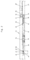
- the locking device 24 shows in Fig. 2 a bolt 25, which by means of a Face plate 26 in the fitting receiving groove 27 of the lower, horizontal Wing spar 17 is struck on the middle wing 5.
- a Slide 29 associated pin 30 is provided on the end face of the Head a tool engagement 31, for example a hexagon socket and by twisting using an actuating tool, for example, a hexagon socket wrench a pressure adjustment Slider 29 allows.
- the pressure adjustment is important if i.e. the pin 30 has to the counterpart, the striker 32 with play be acted upon not to the operation of the bolt 25 affect.
- a spacer 33 is provided in the region of the pin 30, as much as possible Space for an energy storage device 34 creates.
- the energy storage device 34 is in direct connection with a cutout 35 of the slide 29 and that the other end passes through a cutout 36 of the faceplate 26.
- the force storage device 34 which is designed here as a tension spring, is preferably symmetrical, so that there is no assembly error can undermine.
- the energy storage device 34 is almost in one relaxed state, i.e. the pin 30 is from the striker 32 extended and the slider 29 is due to the spring characteristic of the Energy storage device 34 has been transferred into a free operating field, so that the side wing 3 - not shown here - in the open state located and the middle wing 5 can be opened.
- the slide that is preferably made from a flat band material in the region 37 angled.
- a guide piece 38 attached to the bottom of the Betschaufnahmut 27 supports the slide 29 in a certain position leads and at the same time serves as a guide for fastening screws that the Locking device 24 attached to the horizontal wing spars 17.
- a cover cap 40 is provided which is pushed onto the slide 29 and via a convex shape 41 of the slide 29 in the two sides for it the cap 40 provided eyes 42 - for right and Left usability - clicks into place. 3 is also clearly visible see that the cap 40 has a ramp 43, the is designed on one side to achieve the largest possible run-up area. With of the ramp slopes 43, the stroke of the bolt 25 can be determined.
- FIG. 5 and 6 show a profile section of the multi-sash window 1 in the area of the middle wing 5 and the side wing 3, the wing spars 6 and 7 with internal blow bar 22 are cut, in Fig. 5 is the Side wing 3 and the center wing 5 in the closed position and the Locking device 24 is - not shown here in the picture - in one 4, the slide directly bears against the sash rebate 45 of the sash 6.
- the pin 30 is with the Striker 32 in locking engagement and the middle wing 5 can therefore be Do not open. 6, however, is in a slightly open one Rotary position.
- the locking device 4 is easy in one 2 and 3, the pin 30 from the Striker 32 has moved out and the middle wing 5 after unlocking the Folding gear can be opened.
- Fig. 5 is the Side wing 3 and the center wing 5 in the closed position and the Locking device 24 is - not shown here in the picture - in one 4, the slide directly bears against the sash rebate 45 of the sash 6.
- the pin 30
- the latch-like closure 50 has an energy accumulator 64, which preferably consists of a compression spring, the energy accumulator 64 acting on the locking member 51 in a permanently resilient manner.
- the latch-like closure is fastened, for example, by fastening screws (not shown), the fastening screw which engages in the countersunk hole 65 being a threaded screw and making a positive connection with the faceplate 26.
- the other fastening screw, which passes through the countersunk hole 66, is also used as the fastening of the locking device 24.
- the locking piece 51 has a section 67 which adapts to the shape of the inclusion surface of the closing piece 32, as shown in FIG. 7b.
- a clutch shoe 60 arranged with the slide 29 in a detachable connection.
- the slide 29 has one Tooth section 68, in which the clutch shoe 60, also with Longitudinal gears 61 is fitted, forms a positive connection.
- latching means 62 holds the set position and thus secures the Coupling shoe 60 against falling out, but on the other hand it is also so designed that the preset position even when installed can be changed at any time.
- the clutch shoe 60 which consists of the longitudinal teeth 61 and one Run-up bevels 63 is preferably made of a molded plastic part manufactured, but also training as a corresponding casting possible.
- the advantages of the clutch shoe 60 are that the Compensate stroke and first wing tolerances with the simplest of means to let.
- there is preferably a tooth coupling was chosen because it is a simple and technically low-cost variant and on the other hand fine-tuning is produced. Other coupling options are also conceivable result from the prior art.
Landscapes
- Engineering & Computer Science (AREA)
- Mechanical Engineering (AREA)
- Closing And Opening Devices For Wings, And Checks For Wings (AREA)
Abstract
Description
- Fig. 1
- die schematisch vereinfachte Hauptansicht eines Dreiflügel-Fensters vom Rauminneren her betrachtet,
- Fig. 2
- in einem größeren Maßstab das im Bereich I der Fig. 1 zwischen dem Mittelflügel und dem Seitenflügel des Dreiflügel-Fensters verdeckt eingebaute Verriegelungsvorrichtung in einer Vorderansicht,
- Fig. 3
- die Verriegelungsvorrichtung nach Fig. 2 in einer Draufsicht mit einem angedeuteten Schließstück,
- Fig. 4
- die Verriegelungsvorrichtung ebenfalls in einer Draufsicht, wobei sich die Verriegelungsvorrichtungen in einer Schließposition mit dem angedeuteten Schließstück befindet,
- Fig. 5
- das Mehrflügel-Fenster in einem Profilschnitt im Bereich des Mittelflügels und des Seitenflügels in Verschlussstellung,
- Fig. 6
- nach Fig. 5 in einer geöffneten Stellung des Seitenflügel,
- Fig. 7a
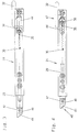
- in einem größeren Maßstab das im Bereich I in der Fig. 1 zwischen dem Mittelflügel und dem Seitenflügel des Dreiflügel-Fensters verdeckt eingebaute Verriegelungsvorrichtung in einer Vorderansicht,
- Fig. 7b
- die Verriegelungsvorrichtung in einer Draufsicht, wobei sich die Verriegelungsvorrichtung in einer Schließposition mit dem angedeuteten Schließstück befindet,
- Fig. 8
- die Verriegelungsvorrichtung nach Fig. 7b ebenfalls in einer Draufsicht, in geöffneter Position des Seitenflügels und geschlossener Position des Mittelflügels nach Fig. 6,
- Fig. 9
- die Verriegelungsvorrichtung nach Fig. 7b, wobei der Seitenflügel bereits geschlossen ist und der Mittelflügel sich in geöffneter Position befindet,
- Fig. 10
- in einem größeren Maßstab das im Bereich II der Fig. 7b gezeigte Ende und
- Fig. 11
- nach Fig. 10 in verstellter Position des Kupplungsschuhs.
Damit das Riegelglied 51 des Verschlusses 50 auch bei betätigter Verriegelungsvorrichtung 24 das Schließstück 32 überwinden kann, nach Fig. 9, muss gewährleistet sein, dass das Riegelglied 51 mit dem Kraftspeicher 64 unabhängig von der Verriegelungsvorrichtung 24 und dem Schieber 29 arbeitet. D. h., dass der Schieber 29 mit einem Mittel 69 des Verschlusses 50 direkt gekuppelt ist, wobei das Mittel 69 das Riegelglied 51 und den Kraftspeicher 64 aufnimmt und das Mittel 69 den Hub des Schiebers 22 überträgt. Um den Kraftaufwand zur Überwindung des Schließstücks 32 möglichst gering zu halten, ist an dem Riegelglied 51 eine Einlaufschräge 53 vorgesehen, die diametral zu der Auflaufschrägen 63 verläuft und damit auf der Seite zum Schließstück 32 angeordnet ist.
- 1
- Mehrflügel-Fenster
- 2
- Rahmen
- 3
- Flügelrahmen (Seitenflügel)
- 4
- Flügelrahmen (Seitenflügel)
- 5
- Flügelrahmen (Mittelflügel)
- 6
- Flügelholm
- 7
- Flügelholm
- 8
- Flügelholm
- 9
- Flügelholm
- 10
- aufrechter Flügelholm
- 11
- aufrechter Flügelholm
- 12
- horizontaler Flügelholm
- 13
- horizontaler Flügelholm
- 14
- horizontaler Flügelholm
- 15
- horizontaler Flügelholm
- 16
- horizontaler Flügelholm
- 17
- horizontaler Flügelholm
- 18
- aufrechter Rahmenholm
- 19
- aufrechter Rahmenholm
- 20
- horizontaler Rahmenholm
- 21
- horizontaler Rahmenholm
- 22
- innenliegende Schlagleiste
- 23
- innenliegende Schlagleiste
- 24
- Verriegelungsvorrichtung
- 25
- Riegel
- 26
- Stulpschiene
- 27
- Beschlagaufnahmenut
- 28
- Blendrahmenfalz
- 29
- Schieber
- 30
- Zapfen
- 31
- Werkzeugeingriff
- 32
- Schließstück
- 33
- Distanzscheibe
- 34
- Kraftspeichervorrichtung
- 35
- Ausschnitt
- 36
- Ausschnitt
- 37
- abgewinkelter Bereich
- 38
- Führungsstück
- 39
- Ende
- 40
- Abdeckkappe
- 41
- Ausprägung
- 42
- Auge
- 43
- Auflaufschräge
- 44
- Langloch
- 45
- Flügelfalz
- 46
- Anschlagkante
- 47
- Schließposition
- 48
- Ende
- 50
- Verschluss
- 51
- Riegelglied
- 52
- Ausrückseite
- 53
- Einlaufschräge
- 60
- Kupplungsschuh
- 61
- Längsverzahnungen
- 62
- Rastmittel
- 63
- Auflaufschräge
- 64
- Kraftspeicher
- 65
- Senkloch
- 66
- Senkloch
- 67
- Abschnitt
- 68
- Zahnabschnitt
- 69
- Mittel
Claims (20)
- Verriegelungsvorrichtung (24) für mindestens dreiflügelige Fenster und Türen ohne Mittelpfosten mit innenliegender Schlagleiste(22, 23), bestehend aus einem Riegel (25) und einem Schließstück (32),
dadurch gekennzeichnet,
daß der Riegel (25) am Flügelrahmen (5) angebracht ist, der an zwei benachbarte Flügelrahmen (3, 4) angrenzt, wobei der Flügelrahmen (5) von einem der benachbarten Flügelrahmen (3) oder (4) an der Drehachse mittels der innenliegenden Schlagleiste (22) oder (23) übergriffen wird und der Riegel (25) mit einem der übergreifenden Flügelrahmen (3) oder (4) verriegelnd zusammenwirkt. - Verriegelungsvorrichtung nach Anspruch 1,
dadurch gekennzeichnet,
daß der Riegel (25) nach Öffnen des benachbarten Flügelrahmens (3) oder (4) selbsttätig aus dem Sperreingriff herausgefahren ist und den vorher in Schließposition befindlichen Flügelrahmen (5) freigibt. - Verriegelungsvorrichtung nach Anspruch 1 und 2,
dadurch gekennzeichnet,
daß der Riegel (25) und das Schließstück (32) verdeckt im Flügelfalz (45) des Fensters oder der Tür (1) angeordnet ist, wobei der Riegel (25) am Flügelrahmen (5) in einer Beschlagaufnahmenut (27) und das Schließstück (32) am Rahmen (2) befestigt ist. - Verriegelungsvorrichtung nach einem der Ansprüche 1 bis 3,
dadurch gekennzeichnet,
daß der Riegel (25) eine Kraftspeichervorrichtung (34) aufweist, wobei das eine Ende der Kraftspeichervorrichtung (34) in direkter Verbindung mittels eines Ausschnittes (35) im Schieber (29) und einem dem Schieber (29) zugehörigen Zapfen (30) steht und das andere Ende einen Ausschnitt (36) einer Stulpschiene (26) durchgreift. - Verriegelungsvorrichtung nach Anspruch 4,
dadurch gekennzeichnet,
daß die Kraftspeichervorrichtung (34) eine Zug- oder Druckfeder ist. - Verriegelungsvorrichtung nach einem der Ansprüche 1 bis 5,
dadurch gekennzeichnet,
daß der Schieber (29) mit seinem einen Ende (39) in Schließposition (47) am Blendrahmenfalz (28) des benachbarten Flügelrahmen (3, 4) anliegt und sich dabei aufgrund der Federcharakteristik der Kraftspeichervorrichtung (34) in einer anhaltend konstanten Dauerspannung befindet. - Verriegelungsvorrichtung nach einem der vorhergehenden Ansprüche,
daß der Riegel (25) längssymmetrisch ausgebildet ist. - Verriegelungsvorrichtung nach einem der vorhergehenden Ansprüche,
dadurch gekennzeichnet,
daß der Schieber (29) aus einem flachen Bandmaterial besteht und nahe der Kraftspeichervorrichtung (34) einen abgewinkelten Bereich (37) aufweist. - Verriegelungsvorrichtung nach einem der vorhergehenden Ansprüche,
dadurch gekennzeichnet,
daß der Schieber (29) an dem des zum benachbarten Flügelrahmen (3, 4) weisenden Ende (48) eine Abdeckkappe (40) aufweist, die mit einer Auflaufschrägen (43) versehen ist. - Verriegelungsvorrichtung nach Anspruch 9,
dadurch gekennzeichnet,
daß die Abdeckkappe (40) vorzugsweise aus einem Kunststoff besteht. - Verriegelungsvorrichtung nach einem der vorhergehenden Ansprüche,
dadurch gekennzeichnet,
daß an dem Schieber (29) ein Zapfen (30) befestigt ist, der die Stulpschiene (26) in einem Langloch (44) durchgreift und in Schließposition (47) das Schließstück (32) hintergreift. - Verriegelungsvorrichtung nach einem der vorhergehenden Ansprüche,
dadurch gekennzeichnet,
daß das Schließstück (32) und die Abdeckkappe (40), der Zapfen (30) Standardbeschlagbauteile sind. - Verriegelungsvorrichtung nach Anspruch 1,
dadurch gekennzeichnet,
dass die Verriegelungsvorrichtung (24) an dem Schließstück (32) zugewandten Ende einen fallenartigen Verschluss (50) aufweist. - Verriegelungsvorrichtung nach Anspruch 13,
dadurch gekennzeichnet,
dass der Verschluss (50) ein Riegelglied (31) aufweist, das an seiner Ausrückseite (52) eine Einlaufschräge (53) trägt, die diametral zu der Auflaufschrägen (63) verläuft und damit auf der Seite zum Schließstück (32) angeordnet ist. - Verriegelungsvorrichtung nach mindestens einem der
Ansprüche 13 bis 14,
dadurch gekennzeichnet, dass der fallenartige Verschluss (50) ein vorhandenes Serienteil ist. - Verriegelungsvorrichtung nach Anspruch 1,
dadurch gekennzeichnet,
dass die Verriegelungsvorrichtung (24) an dem Ende (48) einen Kupplungsschuh (60) trägt, der mit dem Schieber (29) kuppelbar ist und um ein oder mehrere Rastermaße längsverschiebbar ist. - Verriegelungsvorrichtung nach Anspruch 16,
dadurch gekennzeichnet,
dass an dem Kupplungsschuh (60) und an dem Schieber (29) jeweils zueinander komplementäre und hochkant angeordnete Längsverzahnungen (61) ausgebildet sind. - Verriegelungsvorrichtung nach mindestens einem der Ansprüche 16 bis 17,
dadurch gekennzeichnet,
dass der Kupplungsschuh (60) ein Rastmittel (62) zum Fixieren der Verbindung zwischen dem Kupplungsschuh (60) und dem Schieber (29) aufweist. - Verriegelungsvorrichtung nach mindestens einem der Ansprüche 16 bis 18,
dadurch gekennzeichnet,
dass mit dem Kupplungsschuh (60) eine Auflaufschräge (63) in - vorzugsweise einstückiger ― Verbindung steht, welcher aus dem Ende (48) der Verriegelungsvorrichtung (24) herausschiebbar ist und dabei bezüglich seiner wirksamen Riegellänge zwischen dem Minimalmaß (Fig. 10) und einem Maximalmaß (Fig. 11) stufenweise variierbar ist. - Verriegelungsvorrichtung nach mindestens einem der. Ansprüche 16 bis 19,
dadurch gekennzeichnet,
dass der Kupplungsschuh (60) ein Kunststoff-Spritzteil ist.
Applications Claiming Priority (4)
| Application Number | Priority Date | Filing Date | Title |
|---|---|---|---|
| DE1999136018 DE19936018A1 (de) | 1999-08-04 | 1999-08-04 | Verriegelungsvorrichtung für mindestens dreiflügelige Fenster und Türen ohne Mittelpfosten mit innenliegender Schlagleiste |
| DE19936018 | 1999-08-04 | ||
| DE2000111991 DE10011991A1 (de) | 1999-08-04 | 2000-03-11 | Verriegelungsvorrichtung für mindestens dreiflügelige Fenster und Türen ohne Mittelpfosten mit innenliegender Schlagleiste |
| DE10011991 | 2000-03-11 |
Publications (1)
| Publication Number | Publication Date |
|---|---|
| EP1074683A1 true EP1074683A1 (de) | 2001-02-07 |
Family
ID=26004806
Family Applications (1)
| Application Number | Title | Priority Date | Filing Date |
|---|---|---|---|
| EP00108881A Withdrawn EP1074683A1 (de) | 1999-08-04 | 2000-04-26 | Verriegelungsvorrichtung für mindestens dreiflügelige Fenster und Türen |
Country Status (2)
| Country | Link |
|---|---|
| EP (1) | EP1074683A1 (de) |
| DE (1) | DE10011991A1 (de) |
Cited By (2)
| Publication number | Priority date | Publication date | Assignee | Title |
|---|---|---|---|---|
| NL1027867C2 (nl) * | 2004-12-23 | 2006-06-26 | Lips Nederland B V | Schootinrichting voor een slot. |
| EP2907947A1 (de) | 2014-02-18 | 2015-08-19 | Ferco | Verriegelungsvorrichtung für halbfesten Fenster- oder Türflügel |
Citations (10)
| Publication number | Priority date | Publication date | Assignee | Title |
|---|---|---|---|---|
| DE238421C (de) * | ||||
| NL65790C (de) * | 1900-01-01 | |||
| DE813513C (de) * | 1949-12-31 | 1951-09-13 | Franz Binzberger | Dreiteiliger Beschlag fuer zweiflueglige Tueren, insbesondere an Moebeln |
| US2581885A (en) * | 1948-12-22 | 1952-01-08 | Stanley Works | Connecting means for door latches |
| DE7206106U (de) | 1972-07-27 | Ruessel A | Fenster mit Verriegelungsvorrichtung | |
| DE3039515A1 (de) | 1980-01-09 | 1981-07-16 | Lapp-Finze Eisenwarenfabriken AG, 8401 Kalsdorf, Graz | Verriegelungsvorrichtung fuer einen drehfluegel eines doppelfluegelfensters |
| US4907908A (en) * | 1987-10-28 | 1990-03-13 | Siegenia-Frank Kg | Adjustable rod joint |
| EP0668426A1 (de) * | 1994-02-18 | 1995-08-23 | AUBI Baubeschläge GmbH | Beschlag für Fenster oder Türen |
| EP0748911A1 (de) * | 1995-06-13 | 1996-12-18 | Siegenia-Frank Kg | Treibstangen-Verschlussvorrichtung für die Flügel von Fenstern, Türen od. dgl. |
| EP0808974A2 (de) * | 1996-05-22 | 1997-11-26 | Siegenia-Frank Kg | Schnappriegelvorrichtung für Flügel von Fenstern, Türen oder dgl. |
-
2000
- 2000-03-11 DE DE2000111991 patent/DE10011991A1/de not_active Withdrawn
- 2000-04-26 EP EP00108881A patent/EP1074683A1/de not_active Withdrawn
Patent Citations (10)
| Publication number | Priority date | Publication date | Assignee | Title |
|---|---|---|---|---|
| DE238421C (de) * | ||||
| NL65790C (de) * | 1900-01-01 | |||
| DE7206106U (de) | 1972-07-27 | Ruessel A | Fenster mit Verriegelungsvorrichtung | |
| US2581885A (en) * | 1948-12-22 | 1952-01-08 | Stanley Works | Connecting means for door latches |
| DE813513C (de) * | 1949-12-31 | 1951-09-13 | Franz Binzberger | Dreiteiliger Beschlag fuer zweiflueglige Tueren, insbesondere an Moebeln |
| DE3039515A1 (de) | 1980-01-09 | 1981-07-16 | Lapp-Finze Eisenwarenfabriken AG, 8401 Kalsdorf, Graz | Verriegelungsvorrichtung fuer einen drehfluegel eines doppelfluegelfensters |
| US4907908A (en) * | 1987-10-28 | 1990-03-13 | Siegenia-Frank Kg | Adjustable rod joint |
| EP0668426A1 (de) * | 1994-02-18 | 1995-08-23 | AUBI Baubeschläge GmbH | Beschlag für Fenster oder Türen |
| EP0748911A1 (de) * | 1995-06-13 | 1996-12-18 | Siegenia-Frank Kg | Treibstangen-Verschlussvorrichtung für die Flügel von Fenstern, Türen od. dgl. |
| EP0808974A2 (de) * | 1996-05-22 | 1997-11-26 | Siegenia-Frank Kg | Schnappriegelvorrichtung für Flügel von Fenstern, Türen oder dgl. |
Cited By (3)
| Publication number | Priority date | Publication date | Assignee | Title |
|---|---|---|---|---|
| NL1027867C2 (nl) * | 2004-12-23 | 2006-06-26 | Lips Nederland B V | Schootinrichting voor een slot. |
| EP2907947A1 (de) | 2014-02-18 | 2015-08-19 | Ferco | Verriegelungsvorrichtung für halbfesten Fenster- oder Türflügel |
| FR3017645A1 (fr) * | 2014-02-18 | 2015-08-21 | Ferco | Dispositif de verrouillage pour vantail semi-fixe de porte ou fenetre |
Also Published As
| Publication number | Publication date |
|---|---|
| DE10011991A1 (de) | 2001-09-13 |
Similar Documents
| Publication | Publication Date | Title |
|---|---|---|
| EP3102759B1 (de) | Beschlag eines zumindest hebbaren und verschiebbaren flügels von fenstern oder türen | |
| EP0786574B1 (de) | Verriegelungsbeschlag zur Verriegelung eines Fenster- oder Türflügels am Blendrahmen | |
| EP0969176A2 (de) | Rahmenloser Glasflügel als beweglich gelagerter oder ortsfester Flügel einer Tür, eines Fensters oder einer Fassade oder Glaswand | |
| EP0816616B1 (de) | Laufelement | |
| DE202013008784U1 (de) | Beschlag eines zumindest hebbaren, vorzugsweise aber auch verschiebbaren Flügels von Fenstern oder Türen | |
| EP0761920B1 (de) | Fenster/Tür mit Dreh-Kipp-Beschlag | |
| EP0844348A1 (de) | Band für Türen oder Fenster | |
| EP0945579A2 (de) | Lüftungseinrichtung | |
| EP2149661A1 (de) | Gebäudeabschluss in sprengwirkungshemmender und/oder einbruchhemmender Ausführung | |
| EP3443185B1 (de) | Beschlag zweier zumindest hebbarer und verschiebbarer flügel von fenstern oder türen | |
| DE19806727A1 (de) | Fenster- oder Türverschluß | |
| DE602004007009T2 (de) | Verbessertes kippfenster mit arretiermittel | |
| DE10011991A1 (de) | Verriegelungsvorrichtung für mindestens dreiflügelige Fenster und Türen ohne Mittelpfosten mit innenliegender Schlagleiste | |
| DE19745553A1 (de) | Schließvorrichtung | |
| DE19906071C2 (de) | Drehbegrenzer für Dreh-Schiebe-Fenster | |
| EP3235988A1 (de) | Fenstersystem und/oder türsystem | |
| EP0733761B1 (de) | Flügelrahmen | |
| DE4200868A1 (de) | Zusatz-schliesseinrichtung fuer fenster | |
| EP0748911B1 (de) | Treibstangen-Verschlussvorrichtung für die Flügel von Fenstern, Türen od. dgl. | |
| DE19929818A1 (de) | Beschlag für ein Fenster oder eine Tür mit einer Spaltöffnungsstellung | |
| EP3553260B1 (de) | Falleneinsatz mit tagstellung zur bedingten freigabe einer schlossfalle eines türschlossmechanismus | |
| DE69205695T2 (de) | Flügelgelenkband für eine Tür, ein Fenster oder dergleichen von dem der Flügel nach aussen und um eine senkrechte Achse schwenkt gegenüber einem Fensterrahmen. | |
| DE3008043A1 (de) | Zusatzverriegelung fuer fenster, tueren o.dgl. | |
| DE3446215A1 (de) | Einbruchssicherung bei beschlaegen fuer mehrfluegelige fenster | |
| DE102006035416B4 (de) | Verschluss für einen Treibstangenbeschlag |
Legal Events
| Date | Code | Title | Description |
|---|---|---|---|
| PUAI | Public reference made under article 153(3) epc to a published international application that has entered the european phase |
Free format text: ORIGINAL CODE: 0009012 |
|
| AK | Designated contracting states |
Kind code of ref document: A1 Designated state(s): AT BE CH CY DE DK ES FI FR GB GR IE IT LI LU MC NL PT SE |
|
| AX | Request for extension of the european patent |
Free format text: AL;LT;LV;MK;RO;SI |
|
| 17P | Request for examination filed |
Effective date: 20010222 |
|
| AKX | Designation fees paid |
Free format text: AT BE CH CY DE DK ES FI FR GB GR IE IT LI LU MC NL PT SE |
|
| RAP1 | Party data changed (applicant data changed or rights of an application transferred) |
Owner name: SIEGENIA-AUBI KG |
|
| RAP1 | Party data changed (applicant data changed or rights of an application transferred) |
Owner name: SIEGENIA-AUBI KG |
|
| 17Q | First examination report despatched |
Effective date: 20040209 |
|
| RAP1 | Party data changed (applicant data changed or rights of an application transferred) |
Owner name: SIEGENIA-AUBI KG |
|
| STAA | Information on the status of an ep patent application or granted ep patent |
Free format text: STATUS: THE APPLICATION IS DEEMED TO BE WITHDRAWN |
|
| 18D | Application deemed to be withdrawn |
Effective date: 20040622 |