EP1074700A2 - Rotorblatt - Google Patents
Rotorblatt Download PDFInfo
- Publication number
- EP1074700A2 EP1074700A2 EP00306248A EP00306248A EP1074700A2 EP 1074700 A2 EP1074700 A2 EP 1074700A2 EP 00306248 A EP00306248 A EP 00306248A EP 00306248 A EP00306248 A EP 00306248A EP 1074700 A2 EP1074700 A2 EP 1074700A2
- Authority
- EP
- European Patent Office
- Prior art keywords
- blade
- section
- airfoil section
- rotor
- accordance
- Prior art date
- Legal status (The legal status is an assumption and is not a legal conclusion. Google has not performed a legal analysis and makes no representation as to the accuracy of the status listed.)
- Withdrawn
Links
Images


Classifications
-
- F—MECHANICAL ENGINEERING; LIGHTING; HEATING; WEAPONS; BLASTING
- F01—MACHINES OR ENGINES IN GENERAL; ENGINE PLANTS IN GENERAL; STEAM ENGINES
- F01D—NON-POSITIVE DISPLACEMENT MACHINES OR ENGINES, e.g. STEAM TURBINES
- F01D5/00—Blades; Blade-carrying members; Heating, heat-insulating, cooling or antivibration means on the blades or the members
- F01D5/30—Fixing blades to rotors; Blade roots ; Blade spacers
- F01D5/3007—Fixing blades to rotors; Blade roots ; Blade spacers of axial insertion type
-
- F—MECHANICAL ENGINEERING; LIGHTING; HEATING; WEAPONS; BLASTING
- F01—MACHINES OR ENGINES IN GENERAL; ENGINE PLANTS IN GENERAL; STEAM ENGINES
- F01D—NON-POSITIVE DISPLACEMENT MACHINES OR ENGINES, e.g. STEAM TURBINES
- F01D21/00—Shutting-down of machines or engines, e.g. in emergency; Regulating, controlling, or safety means not otherwise provided for
- F01D21/04—Shutting-down of machines or engines, e.g. in emergency; Regulating, controlling, or safety means not otherwise provided for responsive to undesired position of rotor relative to stator or to breaking-off of a part of the rotor, e.g. indicating such position
- F01D21/045—Shutting-down of machines or engines, e.g. in emergency; Regulating, controlling, or safety means not otherwise provided for responsive to undesired position of rotor relative to stator or to breaking-off of a part of the rotor, e.g. indicating such position special arrangements in stators or in rotors dealing with breaking-off of part of rotor
-
- F—MECHANICAL ENGINEERING; LIGHTING; HEATING; WEAPONS; BLASTING
- F01—MACHINES OR ENGINES IN GENERAL; ENGINE PLANTS IN GENERAL; STEAM ENGINES
- F01D—NON-POSITIVE DISPLACEMENT MACHINES OR ENGINES, e.g. STEAM TURBINES
- F01D5/00—Blades; Blade-carrying members; Heating, heat-insulating, cooling or antivibration means on the blades or the members
- F01D5/12—Blades
- F01D5/14—Form or construction
- F01D5/141—Shape, i.e. outer, aerodynamic form
-
- F—MECHANICAL ENGINEERING; LIGHTING; HEATING; WEAPONS; BLASTING
- F04—POSITIVE - DISPLACEMENT MACHINES FOR LIQUIDS; PUMPS FOR LIQUIDS OR ELASTIC FLUIDS
- F04D—NON-POSITIVE-DISPLACEMENT PUMPS
- F04D29/00—Details, component parts, or accessories
- F04D29/26—Rotors specially for elastic fluids
- F04D29/32—Rotors specially for elastic fluids for axial flow pumps
- F04D29/321—Rotors specially for elastic fluids for axial flow pumps for axial flow compressors
- F04D29/324—Blades
Definitions
- This invention relates generally to turbine engines, and more specifically, to a blade for a compressor for such engines.
- a turbine engine typically includes a fan and a low pressure compressor, sometimes referred to as a booster.
- the fan includes a rotor having a plurality of blades.
- the low pressure compressor also includes a rotor having a plurality of rotor blades which extend radially outward across an airflow path.
- the fan rotor is coupled to the booster rotor.
- the blades generally include an airfoil section mounted radially outward of a blade root section.
- the rotor is housed within a stator case.
- a test sometimes referred to as a "blade out” test is run.
- a fan blade is released at its root, which creates an imbalance in the fan rotor. Since the fan rotor is coupled to the booster rotor, the imbalance in the fan rotor affects operation of the booster rotor. Specifically, the blade tips can rub the case. The radial and tangential loads imposed by the blade tips on the case create stresses in the case, which can lead to unexpected failure of stator case skin or flanges.
- the strength of the stator case can be increased.
- the material used to fabricate the stator case can be selected so as to have sufficient strength to withstand stresses caused by rubbing of the rotor blades.
- thicker flanges, thicker stator skin, and additional bolts can be added to increase the stator strength.
- Increasing the stator case strength typically results in increasing the weight and cost of the engine.
- a rotor blade for a turbine engine which are configured to more easily bend, or buckle, than known rotor blades and vanes are described.
- a rotor blade includes a blade root section and an airfoil section configured to more easily bend, or buckle, than known airfoil sections. Providing that the airfoil section more easily bends, or buckles, facilitates reducing the forces on, and damage of, stator components during a blade out event.
- the blade airfoil section extends radially outward along a radial line R AS from the blade root section.
- the radial line R AS extends at an angle relative to a plane extending across a top surface of a platform between the airfoil section and the blade root section, rather than normal, or perpendicular, to such plane.
- FIG. 1 is a schematic illustration of a turbine engine 10.
- Engine 10 includes a low pressure compressor 12, sometimes referred to as a booster, and a fan 14 located immediately upstream from booster 12.
- Engine 10 also includes a high pressure compressor 16, a combustor 18, a high pressure turbine 20 and a low pressure turbine 22.
- Booster 12 and fan 14 are coupled to low pressure turbine 22 by a first shaft 24.
- High pressure compressor 16 is coupled to high pressure turbine 20 by a second shaft 26.
- a typical compressor rotor assembly of a turbine engine includes a plurality of rotor blades extending radially outward across an airflow path.
- An example of a known rotor blade 50 for a low pressure compressor is illustrated in Figure 2.
- Blade 50 includes an airfoil section 52 extending radially outward from a blade root section 54.
- a platform 56 is located between airfoil section 52 and blade root section 54, and platform 56 forms a portion of the boundary between the rotor and the working medium.
- Blade 50 is normally mounted in a rim of a rotor disk with root section 54 interlockingly engaging a slot in the rim.
- Compressor blade roots are curvilinear in form and referred to as dovetail roots and the matching conforming slots are referred to as dovetail slots.
- Blade 50 As shown in Figure 3, which is a front view of blade 50, as blade 50 rotates, gas loads L G act on blade 50. Blade 50 typically is mounted to the rotor disk so that blade 50 is angularly offset, or tilted, so that blade bending created by the gas loads is balanced, or offset, by bending caused by rotation at the airfoil root.
- FIGS 4 and 5 are schematic illustrations of a rotor 60 including a plurality of blades 62 positioned relative to a stator case 64.
- rotor 60 has a trajectory into case 64, and blades 62 contact case 64.
- a load N is transmitted into, and supported by, case 64 from each blade 62 in contact with case 64.
- Arrow D indicates the direction of rotation of rotor 60
- arrow T indicates rotor 60 trajectory into case 64.
- a friction component ⁇ N destabilizes and facilitates buckling of blade 62. More specifically, forces ⁇ N and N force blade 62 to bend and buckle, which allows additional closure between rotor 60 and stator case 64, as shown in Figure 7. It is believed that the forces ⁇ N and N generated by the rubbing of blade 62 on case 64 result in damaging case 64.
- Blade 100 includes an airfoil section 102 extending radially outward from a blade root section 104.
- a platform 106 is located between airfoil section 102 and blade root section 104, and platform 106 forms a portion of the boundary between the rotor and the working medium.
- Blade 100 is normally mounted in a rim of a rotor disk with root section 104 interlockingly engaging a slot in the rim.
- Compressor blade roots are curvilinear in form and referred to as dovetail roots and the matching conforming slots are referred to as dovetail slots.
- Airfoil section 102 extends along a radial line R AS at an angle relative to a plane extending across a top surface of platform 106.
- radial line R AS is straight. More particularly, blade 100 generates an over turning moment at the root of airfoil section 102 which assists in bending blade airfoil section 102 to reduce the load on the stator, e.g., the stator case, during a blade out event. The moment is equal to: NL + ⁇ NH where:
- Blade 200 includes an airfoil section 202 extending radially outward from a blade root section 204.
- a platform 206 is located between airfoil section 202 and blade root section 204, and platform 206 forms a portion of the boundary between the rotor and the working medium.
- Blade 200 is normally mounted in a rim of a rotor disk with root section 204 interlockingly engaging a slot in the rim.
- Airfoil section 202 is bowed, and extends along radial line R AS at an angle relative to a plane extending across a top surface of platform 206.
- radial line R AS is curved.
- the airfoil section (e.g., airfoil section 102, 202) thickness also varies along its length.
- the airfoil section with a varying thickness can extend along a straight radial line R AS as with blade section 102, or along a curved radial line as with blade section 202.
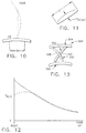
- Figure 10 illustrates reference points, i.e., 0% (the airfoil section root) to 100% (the airfoil section tip) along the airfoil section.
- Figure 11 is a cross section of an airfoil section and illustrates the measurements for the airfoil section thickness T m(ax) and distance C.
- Figure 12 is a graphical representation comparing the ratio of T m /C(Shown as T m(ax) in Figure 11) over the length of the airfoil section (0% to 100%). The ratios of the varying thickness airfoil section are shown in dashed line and the ratios of known airfoil section are shown in solid line. As shown in Figure 12, the varying thickness blade is less thick than known blades for a distance from about 0% to 30% of its length.
- FIG. 13 is a schematic illustration of a blade and vane arrangement 300 in accordance with one embodiment of the present invention.
- Arrangement 300 includes blade 200 and a vane 302.
- Vane 302 has the same curved, or bowed, shape as blade 200, except that vane 302 is secured to stator case 304 rather than to a rotor 306.
- Vane 302 is arranged so that vane 302 opposes blade 200, i.e., concave surfaces 308 and 310 of blade 200 and vane 302, respectively, face each other. This particular arrangement is believed to also reduce aeromechanic excitation.
Landscapes
- Engineering & Computer Science (AREA)
- Mechanical Engineering (AREA)
- General Engineering & Computer Science (AREA)
- Physics & Mathematics (AREA)
- Fluid Mechanics (AREA)
- Structures Of Non-Positive Displacement Pumps (AREA)
- Turbine Rotor Nozzle Sealing (AREA)
Applications Claiming Priority (2)
| Application Number | Priority Date | Filing Date | Title |
|---|---|---|---|
| US09/364,605 US6290465B1 (en) | 1999-07-30 | 1999-07-30 | Rotor blade |
| US364605 | 1999-07-30 |
Publications (2)
| Publication Number | Publication Date |
|---|---|
| EP1074700A2 true EP1074700A2 (de) | 2001-02-07 |
| EP1074700A3 EP1074700A3 (de) | 2004-02-18 |
Family
ID=23435273
Family Applications (1)
| Application Number | Title | Priority Date | Filing Date |
|---|---|---|---|
| EP00306248A Withdrawn EP1074700A3 (de) | 1999-07-30 | 2000-07-21 | Rotorblatt |
Country Status (4)
| Country | Link |
|---|---|
| US (1) | US6290465B1 (de) |
| EP (1) | EP1074700A3 (de) |
| JP (1) | JP2001055996A (de) |
| SG (1) | SG85715A1 (de) |
Cited By (26)
| Publication number | Priority date | Publication date | Assignee | Title |
|---|---|---|---|---|
| FR2828709A1 (fr) * | 2001-08-17 | 2003-02-21 | Snecma Moteurs | Aube de redresseur |
| GB2483061A (en) * | 2010-08-23 | 2012-02-29 | Rolls Royce Plc | A method of damping aerofoil structure vibrations |
| WO2012134835A1 (en) * | 2011-03-25 | 2012-10-04 | General Electric Company | Compressor airfoil with tip dihedral |
| EP3108117A4 (de) * | 2014-02-19 | 2017-03-22 | United Technologies Corporation | Gasturbinenmotorschaufel |
| EP1754859B1 (de) * | 2005-08-16 | 2017-04-26 | General Electric Company | Verfahren und Vorrichtung zur Reduktion von induzierten Schaufelschwingungen |
| US9752439B2 (en) | 2014-02-19 | 2017-09-05 | United Technologies Corporation | Gas turbine engine airfoil |
| US9777580B2 (en) | 2014-02-19 | 2017-10-03 | United Technologies Corporation | Gas turbine engine airfoil |
| US10036257B2 (en) | 2014-02-19 | 2018-07-31 | United Technologies Corporation | Gas turbine engine airfoil |
| US10184483B2 (en) | 2014-02-19 | 2019-01-22 | United Technologies Corporation | Gas turbine engine airfoil |
| US10309414B2 (en) | 2014-02-19 | 2019-06-04 | United Technologies Corporation | Gas turbine engine airfoil |
| US10352331B2 (en) | 2014-02-19 | 2019-07-16 | United Technologies Corporation | Gas turbine engine airfoil |
| US10358925B2 (en) | 2014-02-19 | 2019-07-23 | United Technologies Corporation | Gas turbine engine airfoil |
| US10370974B2 (en) | 2014-02-19 | 2019-08-06 | United Technologies Corporation | Gas turbine engine airfoil |
| US10385866B2 (en) | 2014-02-19 | 2019-08-20 | United Technologies Corporation | Gas turbine engine airfoil |
| US10393139B2 (en) | 2014-02-19 | 2019-08-27 | United Technologies Corporation | Gas turbine engine airfoil |
| US10422226B2 (en) | 2014-02-19 | 2019-09-24 | United Technologies Corporation | Gas turbine engine airfoil |
| US10465702B2 (en) | 2014-02-19 | 2019-11-05 | United Technologies Corporation | Gas turbine engine airfoil |
| US10495106B2 (en) | 2014-02-19 | 2019-12-03 | United Technologies Corporation | Gas turbine engine airfoil |
| US10502229B2 (en) | 2014-02-19 | 2019-12-10 | United Technologies Corporation | Gas turbine engine airfoil |
| US10519971B2 (en) | 2014-02-19 | 2019-12-31 | United Technologies Corporation | Gas turbine engine airfoil |
| US10550852B2 (en) | 2014-02-19 | 2020-02-04 | United Technologies Corporation | Gas turbine engine airfoil |
| US10570916B2 (en) | 2014-02-19 | 2020-02-25 | United Technologies Corporation | Gas turbine engine airfoil |
| US10570915B2 (en) | 2014-02-19 | 2020-02-25 | United Technologies Corporation | Gas turbine engine airfoil |
| US10584715B2 (en) | 2014-02-19 | 2020-03-10 | United Technologies Corporation | Gas turbine engine airfoil |
| US10590775B2 (en) | 2014-02-19 | 2020-03-17 | United Technologies Corporation | Gas turbine engine airfoil |
| US10605259B2 (en) | 2014-02-19 | 2020-03-31 | United Technologies Corporation | Gas turbine engine airfoil |
Families Citing this family (14)
| Publication number | Priority date | Publication date | Assignee | Title |
|---|---|---|---|---|
| US6991428B2 (en) | 2003-06-12 | 2006-01-31 | Pratt & Whitney Canada Corp. | Fan blade platform feature for improved blade-off performance |
| US6899526B2 (en) * | 2003-08-05 | 2005-05-31 | General Electric Company | Counterstagger compressor airfoil |
| US7396205B2 (en) * | 2004-01-31 | 2008-07-08 | United Technologies Corporation | Rotor blade for a rotary machine |
| US7967571B2 (en) * | 2006-11-30 | 2011-06-28 | General Electric Company | Advanced booster rotor blade |
| US8292574B2 (en) | 2006-11-30 | 2012-10-23 | General Electric Company | Advanced booster system |
| US8087884B2 (en) * | 2006-11-30 | 2012-01-03 | General Electric Company | Advanced booster stator vane |
| US8297935B2 (en) * | 2008-11-18 | 2012-10-30 | Honeywell International Inc. | Turbine blades and methods of forming modified turbine blades and turbine rotors |
| FR2989107B1 (fr) * | 2012-04-04 | 2017-03-31 | Snecma | Aube de rotor de turbomachine |
| WO2014031160A1 (en) | 2012-08-22 | 2014-02-27 | United Technologies Corporation | Compliant cantilevered airfoil |
| US10233758B2 (en) | 2013-10-08 | 2019-03-19 | United Technologies Corporation | Detuning trailing edge compound lean contour |
| KR101901682B1 (ko) * | 2017-06-20 | 2018-09-27 | 두산중공업 주식회사 | 제이 타입 캔틸레버드 베인 및 이를 포함하는 가스터빈 |
| US20190010956A1 (en) * | 2017-07-06 | 2019-01-10 | United Technologies Corporation | Tandem blade rotor disk |
| KR102000281B1 (ko) * | 2017-10-11 | 2019-07-15 | 두산중공업 주식회사 | 압축기 및 이를 포함하는 가스 터빈 |
| US12313152B2 (en) | 2023-09-18 | 2025-05-27 | Allison Transmission, Inc. | Torque converter |
Family Cites Families (12)
| Publication number | Priority date | Publication date | Assignee | Title |
|---|---|---|---|---|
| US2962260A (en) * | 1954-12-13 | 1960-11-29 | United Aircraft Corp | Sweep back in blading |
| GB1231424A (de) * | 1968-11-15 | 1971-05-12 | ||
| JPS5262712A (en) * | 1975-11-20 | 1977-05-24 | Agency Of Ind Science & Technol | Axial flow blower |
| US4131387A (en) * | 1976-02-27 | 1978-12-26 | General Electric Company | Curved blade turbomachinery noise reduction |
| US4460315A (en) * | 1981-06-29 | 1984-07-17 | General Electric Company | Turbomachine rotor assembly |
| US4682935A (en) * | 1983-12-12 | 1987-07-28 | General Electric Company | Bowed turbine blade |
| US4995787A (en) * | 1989-09-18 | 1991-02-26 | Torrington Research Company | Axial flow impeller |
| JP2753382B2 (ja) * | 1990-09-17 | 1998-05-20 | 株式会社日立製作所 | 軸流タービン静翼装置及び軸流タービン |
| US5641268A (en) * | 1991-09-17 | 1997-06-24 | Rolls-Royce Plc | Aerofoil members for gas turbine engines |
| GB9210421D0 (en) * | 1992-05-15 | 1992-07-01 | Gec Alsthom Ltd | Turbine blade assembly |
| FR2743845B1 (fr) * | 1996-01-23 | 1998-02-20 | Snecma | Aube mobile de soufflante a profil de securite |
| US6071077A (en) * | 1996-04-09 | 2000-06-06 | Rolls-Royce Plc | Swept fan blade |
-
1999
- 1999-07-30 US US09/364,605 patent/US6290465B1/en not_active Expired - Fee Related
-
2000
- 2000-07-17 SG SG200003970A patent/SG85715A1/en unknown
- 2000-07-21 EP EP00306248A patent/EP1074700A3/de not_active Withdrawn
- 2000-07-27 JP JP2000226248A patent/JP2001055996A/ja active Pending
Cited By (43)
| Publication number | Priority date | Publication date | Assignee | Title |
|---|---|---|---|---|
| FR2828709A1 (fr) * | 2001-08-17 | 2003-02-21 | Snecma Moteurs | Aube de redresseur |
| EP1754859B1 (de) * | 2005-08-16 | 2017-04-26 | General Electric Company | Verfahren und Vorrichtung zur Reduktion von induzierten Schaufelschwingungen |
| GB2483061A (en) * | 2010-08-23 | 2012-02-29 | Rolls Royce Plc | A method of damping aerofoil structure vibrations |
| EP2609297A1 (de) * | 2010-08-23 | 2013-07-03 | Rolls-Royce PLC | Verfahren zur dämpfung von tragflächenstrukturvibrationen und entsprechende tragflächenstruktur |
| WO2012134835A1 (en) * | 2011-03-25 | 2012-10-04 | General Electric Company | Compressor airfoil with tip dihedral |
| CN103459774A (zh) * | 2011-03-25 | 2013-12-18 | 通用电气公司 | 具有末梢上反角的压缩机翼型件 |
| US8684698B2 (en) | 2011-03-25 | 2014-04-01 | General Electric Company | Compressor airfoil with tip dihedral |
| CN103459774B (zh) * | 2011-03-25 | 2016-05-04 | 通用电气公司 | 具有末梢上反角的压缩机翼型件 |
| US10422226B2 (en) | 2014-02-19 | 2019-09-24 | United Technologies Corporation | Gas turbine engine airfoil |
| US10550852B2 (en) | 2014-02-19 | 2020-02-04 | United Technologies Corporation | Gas turbine engine airfoil |
| US9777580B2 (en) | 2014-02-19 | 2017-10-03 | United Technologies Corporation | Gas turbine engine airfoil |
| US9988908B2 (en) | 2014-02-19 | 2018-06-05 | United Technologies Corporation | Gas turbine engine airfoil |
| US10036257B2 (en) | 2014-02-19 | 2018-07-31 | United Technologies Corporation | Gas turbine engine airfoil |
| US10184483B2 (en) | 2014-02-19 | 2019-01-22 | United Technologies Corporation | Gas turbine engine airfoil |
| US10309414B2 (en) | 2014-02-19 | 2019-06-04 | United Technologies Corporation | Gas turbine engine airfoil |
| US10352331B2 (en) | 2014-02-19 | 2019-07-16 | United Technologies Corporation | Gas turbine engine airfoil |
| US10358925B2 (en) | 2014-02-19 | 2019-07-23 | United Technologies Corporation | Gas turbine engine airfoil |
| US10370974B2 (en) | 2014-02-19 | 2019-08-06 | United Technologies Corporation | Gas turbine engine airfoil |
| US10385866B2 (en) | 2014-02-19 | 2019-08-20 | United Technologies Corporation | Gas turbine engine airfoil |
| US10393139B2 (en) | 2014-02-19 | 2019-08-27 | United Technologies Corporation | Gas turbine engine airfoil |
| EP3108117A4 (de) * | 2014-02-19 | 2017-03-22 | United Technologies Corporation | Gasturbinenmotorschaufel |
| US10465702B2 (en) | 2014-02-19 | 2019-11-05 | United Technologies Corporation | Gas turbine engine airfoil |
| US10495106B2 (en) | 2014-02-19 | 2019-12-03 | United Technologies Corporation | Gas turbine engine airfoil |
| US10502229B2 (en) | 2014-02-19 | 2019-12-10 | United Technologies Corporation | Gas turbine engine airfoil |
| US10519971B2 (en) | 2014-02-19 | 2019-12-31 | United Technologies Corporation | Gas turbine engine airfoil |
| US9752439B2 (en) | 2014-02-19 | 2017-09-05 | United Technologies Corporation | Gas turbine engine airfoil |
| EP3108117B1 (de) | 2014-02-19 | 2020-02-05 | United Technologies Corporation | Gasturbinenmotorschaufel |
| US10557477B2 (en) | 2014-02-19 | 2020-02-11 | United Technologies Corporation | Gas turbine engine airfoil |
| US10570916B2 (en) | 2014-02-19 | 2020-02-25 | United Technologies Corporation | Gas turbine engine airfoil |
| US10570915B2 (en) | 2014-02-19 | 2020-02-25 | United Technologies Corporation | Gas turbine engine airfoil |
| US10584715B2 (en) | 2014-02-19 | 2020-03-10 | United Technologies Corporation | Gas turbine engine airfoil |
| US10590775B2 (en) | 2014-02-19 | 2020-03-17 | United Technologies Corporation | Gas turbine engine airfoil |
| US10605259B2 (en) | 2014-02-19 | 2020-03-31 | United Technologies Corporation | Gas turbine engine airfoil |
| US10890195B2 (en) | 2014-02-19 | 2021-01-12 | Raytheon Technologies Corporation | Gas turbine engine airfoil |
| US10914315B2 (en) | 2014-02-19 | 2021-02-09 | Raytheon Technologies Corporation | Gas turbine engine airfoil |
| US11041507B2 (en) | 2014-02-19 | 2021-06-22 | Raytheon Technologies Corporation | Gas turbine engine airfoil |
| US11193497B2 (en) | 2014-02-19 | 2021-12-07 | Raytheon Technologies Corporation | Gas turbine engine airfoil |
| US11193496B2 (en) | 2014-02-19 | 2021-12-07 | Raytheon Technologies Corporation | Gas turbine engine airfoil |
| US11209013B2 (en) | 2014-02-19 | 2021-12-28 | Raytheon Technologies Corporation | Gas turbine engine airfoil |
| US11391294B2 (en) | 2014-02-19 | 2022-07-19 | Raytheon Technologies Corporation | Gas turbine engine airfoil |
| US11408436B2 (en) | 2014-02-19 | 2022-08-09 | Raytheon Technologies Corporation | Gas turbine engine airfoil |
| US11767856B2 (en) | 2014-02-19 | 2023-09-26 | Rtx Corporation | Gas turbine engine airfoil |
| US11867195B2 (en) | 2014-02-19 | 2024-01-09 | Rtx Corporation | Gas turbine engine airfoil |
Also Published As
| Publication number | Publication date |
|---|---|
| JP2001055996A (ja) | 2001-02-27 |
| SG85715A1 (en) | 2002-01-15 |
| US6290465B1 (en) | 2001-09-18 |
| EP1074700A3 (de) | 2004-02-18 |
Similar Documents
| Publication | Publication Date | Title |
|---|---|---|
| EP1074700A2 (de) | Rotorblatt | |
| EP2743453B1 (de) | Konische Teilbereichsummantelung | |
| US8573945B2 (en) | Compressor stator vane | |
| RU2495254C2 (ru) | Лопатка рабочего колеса компрессора с переменным эллиптическим соединением | |
| JP4721638B2 (ja) | バケット固有振動数を調整するための方法及び装置 | |
| US10018050B2 (en) | Turbomachine rotor blade | |
| JP3178327B2 (ja) | 蒸気タービン | |
| US8075272B2 (en) | Steam turbine rotating blade for a low pressure section of a steam turbine engine | |
| US5435694A (en) | Stress relieving mount for an axial blade | |
| EP1477634A2 (de) | Schwingungsdämpfer für Turbinenschaufeln | |
| US4460315A (en) | Turbomachine rotor assembly | |
| US10190423B2 (en) | Shrouded blade for a gas turbine engine | |
| WO2008097287A2 (en) | Aero-mixing of rotating blade structures | |
| JPH0141839B2 (de) | ||
| US8096775B2 (en) | Steam turbine rotating blade for a low pressure section of a steam turbine engine | |
| US8057187B2 (en) | Steam turbine rotating blade for a low pressure section of a steam turbine engine | |
| JPH03138404A (ja) | 蒸気タービン用の羽根 | |
| US20040191068A1 (en) | Moving-blade row for fluid-flow machines | |
| EP1471209A2 (de) | Vorrichtung zur Verminderung von Schwingungen einer Gasturbinenschaufel | |
| US20210079794A1 (en) | Damping device | |
| CN103850716B (zh) | 泪滴形的部分跨距围带 | |
| US8210822B2 (en) | Dovetail for steam turbine rotating blade and rotor wheel | |
| US20070098562A1 (en) | Blade | |
| US20240352861A1 (en) | Turbine airfoil attachment with serration profile | |
| US20050214120A1 (en) | High speed rotor assembly shroud |
Legal Events
| Date | Code | Title | Description |
|---|---|---|---|
| PUAI | Public reference made under article 153(3) epc to a published international application that has entered the european phase |
Free format text: ORIGINAL CODE: 0009012 |
|
| AK | Designated contracting states |
Kind code of ref document: A2 Designated state(s): AT BE CH CY DE DK ES FI FR GB GR IE IT LI LU MC NL PT SE |
|
| AX | Request for extension of the european patent |
Free format text: AL;LT;LV;MK;RO;SI |
|
| PUAL | Search report despatched |
Free format text: ORIGINAL CODE: 0009013 |
|
| AK | Designated contracting states |
Kind code of ref document: A3 Designated state(s): AT BE CH CY DE DK ES FI FR GB GR IE IT LI LU MC NL PT SE |
|
| AX | Request for extension of the european patent |
Extension state: AL LT LV MK RO SI |
|
| 17P | Request for examination filed |
Effective date: 20040818 |
|
| AKX | Designation fees paid |
Designated state(s): AT BE CH CY DE DK ES FI FR GB GR IE IT LI LU MC NL PT SE |
|
| 17Q | First examination report despatched |
Effective date: 20041011 |
|
| STAA | Information on the status of an ep patent application or granted ep patent |
Free format text: STATUS: THE APPLICATION IS DEEMED TO BE WITHDRAWN |
|
| 18D | Application deemed to be withdrawn |
Effective date: 20100202 |