EP1074735A2 - Pompe à piston actionnée par excentriques réglables - Google Patents
Pompe à piston actionnée par excentriques réglables Download PDFInfo
- Publication number
- EP1074735A2 EP1074735A2 EP00810698A EP00810698A EP1074735A2 EP 1074735 A2 EP1074735 A2 EP 1074735A2 EP 00810698 A EP00810698 A EP 00810698A EP 00810698 A EP00810698 A EP 00810698A EP 1074735 A2 EP1074735 A2 EP 1074735A2
- Authority
- EP
- European Patent Office
- Prior art keywords
- piston
- eccentric
- movement
- pump
- cylinder
- Prior art date
- Legal status (The legal status is an assumption and is not a legal conclusion. Google has not performed a legal analysis and makes no representation as to the accuracy of the status listed.)
- Withdrawn
Links
- 239000012530 fluid Substances 0.000 description 5
- 230000010363 phase shift Effects 0.000 description 5
- 239000012535 impurity Substances 0.000 description 3
- 239000007788 liquid Substances 0.000 description 3
- 230000002572 peristaltic effect Effects 0.000 description 3
- 238000013459 approach Methods 0.000 description 2
- 230000005540 biological transmission Effects 0.000 description 2
- 230000015271 coagulation Effects 0.000 description 2
- 238000005345 coagulation Methods 0.000 description 2
- 238000002425 crystallisation Methods 0.000 description 2
- 230000008025 crystallization Effects 0.000 description 2
- 238000004519 manufacturing process Methods 0.000 description 2
- 208000031968 Cadaver Diseases 0.000 description 1
- 230000009172 bursting Effects 0.000 description 1
- 238000010276 construction Methods 0.000 description 1
- 230000010355 oscillation Effects 0.000 description 1
- 238000010992 reflux Methods 0.000 description 1
- 230000001105 regulatory effect Effects 0.000 description 1
- 230000000284 resting effect Effects 0.000 description 1
- 238000007789 sealing Methods 0.000 description 1
Images

Classifications
-
- F—MECHANICAL ENGINEERING; LIGHTING; HEATING; WEAPONS; BLASTING
- F04—POSITIVE - DISPLACEMENT MACHINES FOR LIQUIDS; PUMPS FOR LIQUIDS OR ELASTIC FLUIDS
- F04B—POSITIVE-DISPLACEMENT MACHINES FOR LIQUIDS; PUMPS
- F04B7/00—Piston machines or pumps characterised by having positively-driven valving
- F04B7/0003—Piston machines or pumps characterised by having positively-driven valving the distribution member forming both the inlet and discharge distributor for one single pumping chamber
- F04B7/0011—Piston machines or pumps characterised by having positively-driven valving the distribution member forming both the inlet and discharge distributor for one single pumping chamber and having an oscillating movement
-
- F—MECHANICAL ENGINEERING; LIGHTING; HEATING; WEAPONS; BLASTING
- F04—POSITIVE - DISPLACEMENT MACHINES FOR LIQUIDS; PUMPS FOR LIQUIDS OR ELASTIC FLUIDS
- F04B—POSITIVE-DISPLACEMENT MACHINES FOR LIQUIDS; PUMPS
- F04B7/00—Piston machines or pumps characterised by having positively-driven valving
- F04B7/0042—Piston machines or pumps characterised by having positively-driven valving with specific kinematics of the distribution member
- F04B7/0049—Piston machines or pumps characterised by having positively-driven valving with specific kinematics of the distribution member for oscillating distribution members
-
- F—MECHANICAL ENGINEERING; LIGHTING; HEATING; WEAPONS; BLASTING
- F04—POSITIVE - DISPLACEMENT MACHINES FOR LIQUIDS; PUMPS FOR LIQUIDS OR ELASTIC FLUIDS
- F04B—POSITIVE-DISPLACEMENT MACHINES FOR LIQUIDS; PUMPS
- F04B9/00—Piston machines or pumps characterised by the driving or driven means to or from their working members
- F04B9/02—Piston machines or pumps characterised by the driving or driven means to or from their working members the means being mechanical
- F04B9/04—Piston machines or pumps characterised by the driving or driven means to or from their working members the means being mechanical the means being cams, eccentrics or pin-and-slot mechanisms
- F04B9/045—Piston machines or pumps characterised by the driving or driven means to or from their working members the means being mechanical the means being cams, eccentrics or pin-and-slot mechanisms the means being eccentrics
Definitions
- the present invention relates to a pump comprising an axis drive, a cylinder inside which moves a piston, said cylinder comprising two conduits intake / discharge, the drive axis being connected to the piston via two eccentrics.
- the invention relates more particularly to a micropump.
- Document DE 40 04 142 A1 describes a piston machine whose stroke, and therefore the flow, can be changed thanks with two eccentrics.
- the machine has two axes concentric, carrying the two eccentrics, one of which rotates inside each other.
- the inner axis meshes with a internal gear of the external eccentric by means of a cogwheel passing through an interior eccentric light and the outer axis.
- This piston drive device is complex and expensive to carry out, difficult to balance dynamically.
- the length of the cylinder body must be able to be adjusted based on a change in the piston stroke.
- a peristaltic pump which has no valve
- the pump tube does not lend itself to pressure high and is not suitable for a long service life of the pump.
- the flow of a peristaltic pump is not not linear and the risk of bursting of the tube makes the choice of such a pump often inadequate.
- the flow of a peristaltic pump can only be changed by a change of its speed and its accuracy does not exceed ⁇ 5%.
- the purpose of the present invention is to provide a micropump simple and inexpensive to make, safe to use, insensitive to impurities, allowing high precision of adjustment of its flow rate throughout its adjustment range and capable of also work at very high pressure.
- the invention relates to a pump such that defined at entry, comprising at least one member making it possible to phase out the opening of said conduits by relative to the piston stroke.
- Adjusting the flow rate of the micropump according to the invention relies on the phase shift of the opening and closing of inlet / outlet ports relative to the stroke of the or piston (s).
- the micropump shown in Figures 1 and 2 includes a pump body consisting of a block 1 and a plate base 2.
- block 1 seen in elevation, has a general U-shape.
- the two branches of the U are pierced in their upper part by two coaxial circular openings that receive two sockets cylindrical 3.
- the central lower part of block 1 is pierced with a vertical cylindrical opening, which constitutes a cylinder 16 with base plate 2, which constitutes the head when block 1 is mounted on plate 2 by means of four screw 13.
- a piston 4 acts inside the cylinder 16.
- the plate 2 is pierced by two openings which constitute two conduits inlet and outlet 17 and 18.
- the intake ducts 17, 18 communicate with the inside of the cylinder through a small opening diameter and with the outside by diameter ducts upper, which can be threaded (not shown) to allow connection of inlet and outlet pipes of fluid.
- the piston 4 is provided at its lower part with a anchor 10, in the shape of an inverted T, of which the rod part 19 of the T is mounted so that it can slide inside a housing 20 made in the middle part of the piston.
- the lower part of piston 4 is bored so as to form a housing 21 of larger diameter accommodating a spring 14 which rests on the one hand against the bottom of the bore 21 and on the other hand against the bar 22 of the T of the anchor 10.
- the part constituting the bar 22 of the T is therefore pressed by through the spring 14 against the cylinder head and against the openings of the inlet / outlet pipes 17, 18 of the pump.
- the underside of the bar of the T comprises members 23, 24, intended to cooperate with the inputs of inlet / outlet ducts 17, 18 and to play the role of valves.
- the piston 4 has a first housing 25 constituting a slide horizontal inside which is housed a first eccentric 6, mounted on an integral drive shaft 5 of the drive device (not shown) of the pump, of so that the rotation of the shaft 5, which causes the eccentric 6, causes a vertical movement of the piston, that is to say the piston stroke, inside the cylinder and thus modifies the volume of the internal chamber of the cylinder.
- Piston 4 also comprises, opposite the first housing 25, a second housing 26 constituting a vertical slide inside which houses a second eccentric 7, mounted on the shaft 5 so as to impart lateral movement, that is to say a pitching or oscillating movement, at piston 4 when rotating the shaft 5.
- the two eccentrics 6 and 7 are mounted on the shaft 5 of so that we can change their angular position relative, that is to say their phase shift.
- One of the eccentric, 6, can be blocked on the drive shaft 5, using a pin 11, while the other eccentric 7 is mounted on the shaft so that it can be rotated around its axis to adjust its angular position by compared to eccentric 6 blocked on the shaft.
- a nut 8 is mounted on the shaft 5 and passes through the bush 3; he press eccentric 7 and press it against the eccentric 6 via a washer 9.
- the adjustment of the phase shift of the eccentric 7 relative to the eccentric 6 is visible and adjustable thanks to a cutout 27 on eccentric 7.
- connection between the piston 4 and the block 1 to obtain the sealing of the internal chamber of the cylinder 16 can be produced by an O-ring seal 12. It can also be produced by a bellows or skirt device. We can note that an O-ring seal is easy to change but that it is subject greater wear than a bellows device which, if is well chosen, has a very long lifespan.
- Opening the inlet / outlet pipes 17, 18 is carried out by the pivoting of the anchor 10, 19, 22 under the action of the second eccentric 7 acting on the piston 4, one of the members 23, 24 of said anchor resting on one of the two openings when the other opens, regardless of the axial position of the piston.
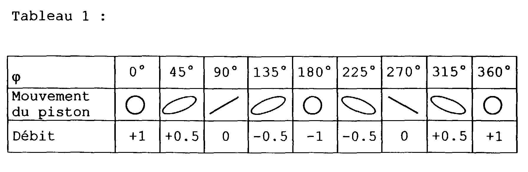
- fluid inlet and outlet are identical, and the flow rate resulting from the pump is zero.
- the piston movement is round and the flow is maximum.
- the movement of the piston becomes elliptical and generates a flow in one direction or the other, lower than the maximum flow.
- the flow and the reflux inside the pump are worth constant and maximum but that the overall resulting flow can vary from maximum to zero without modifying the regime, i.e. the speed of rotation of the pump, nor the stroke of the piston. Due to the mechanical adjustment of the opening of the valves, the presence of an impurity in the fluid to transport, as well as coagulation or crystallization in the case of liquids, no longer risk obstructing the pump operation.
- the flow rate of the micropump according to the invention is extremely precise, since it results from the difference between admission and refoulement.
- the embodiment described above comprises a total of 20 parts, including screws and gaskets.
- the skilled person will easily understand that this number of pieces can be greatly reduced, for example by making the pump body in a single injected part.
- the manufacturing cost of the micropump can therefore be very small, which allows mass production applications, for example in dishwashers professionals.
Landscapes
- Engineering & Computer Science (AREA)
- Mechanical Engineering (AREA)
- General Engineering & Computer Science (AREA)
- Reciprocating Pumps (AREA)
Abstract
Description
- la figure 1 est une vue latérale et en perspective d'une micropompe selon l'invention,
- la figure 2 est une vue en coupe verticale selon le plan XY de la figure 1,
- la figure 3 est une vue en coupe verticale, dans un plan perpendiculaire au plan de la figure 2 de la plaque de base du corps de pompe,
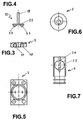
- la figure 4 est une vue en élévation latérale, dans un plan perpendiculaire au plan de la figure 2 de l'ancre 10 de la figure 2,
- la figure 5 est une vue de dessus de la plaque de base de la figure 3,
- la figure 6 est une vue en élévation, par la gauche, de l'excentrique 7 de la figure 2,
- la figure 7 est une vue en élévation, de gauche, du piston 4 de la figure 2.
Claims (5)
- Pompe comportant un axe d'entraínement (5), un cylindre (16) à l'intérieur duquel se déplace un piston (4), ledit cylindre comportant deux conduits d'admission et de refoulement (17, 18), le dit axe d'entraínement étant relié au dit piston par l'intermédiaire de deux excentriques (6, 7), caractérisée en ce que ladite pompe comporte au moins un organe (10) permettant de réaliser un déphasage de l'ouverture desdits conduits par rapport à la course du piston.
- Pompe selon la revendication 1, caractérisée en ce qu'un organe (10) est monté en coulissement à l'extrémité du piston (4), de façon à pousser ledit organe à l'encontre des conduits d'admission (17, 18), l'ensemble étant agencé de façon que l'ouverture d'un des dits conduits d'admission sous l'action du mouvement du piston implique la fermeture de l'autre conduit.
- Pompe selon la revendication 2, caractérisée en ce que ledit organe (10) présente la forme d'un T (19, 22) et porte deux soupapes (23, 24), agencées respectivement en face de deux ouvertures d'admission/refoulement, chacune des deux soupapes étant alternativement pressée contre l'ouverture qui lui fait face sous l'action d'un ressort (14).
- Pompe selon l'une des revendications précédentes, caractérisée en ce qu'elle comporte un premier excentrique (6) et un second excentrique (7) montés respectivement à l'intérieur d'une première coulisse (25) et à l'intérieur d'une seconde coulisse (26) réalisées dans le corps du piston (4), l'ensemble étant agencé de façon que le mouvement dudit premier excentrique dans ladite première coulisse génère un mouvement vertical (course) du piston à l'intérieur du cylindre (16), et en ce que le mouvement du second excentrique dans ladite seconde coulisse génère un mouvement latéral (tangage) dudit piston.
- Pompe selon la revendication 4, caractérisée en ce que les premier (6) et second excentriques (7) sont montés en regard sur l'axe d'entraínement (5) et agencés de façon à pouvoir modifier leur position angulaire relative.
Applications Claiming Priority (2)
| Application Number | Priority Date | Filing Date | Title |
|---|---|---|---|
| CH141999 | 1999-08-02 | ||
| CH141999 | 1999-08-02 |
Publications (2)
| Publication Number | Publication Date |
|---|---|
| EP1074735A2 true EP1074735A2 (fr) | 2001-02-07 |
| EP1074735A3 EP1074735A3 (fr) | 2001-08-22 |
Family
ID=4210020
Family Applications (1)
| Application Number | Title | Priority Date | Filing Date |
|---|---|---|---|
| EP00810698A Withdrawn EP1074735A3 (fr) | 1999-08-02 | 2000-08-02 | Pompe à piston actionnée par excentriques réglables |
Country Status (1)
| Country | Link |
|---|---|
| EP (1) | EP1074735A3 (fr) |
Cited By (1)
| Publication number | Priority date | Publication date | Assignee | Title |
|---|---|---|---|---|
| DE202024105874U1 (de) | 2024-10-11 | 2026-02-19 | Novopress Gmbh Pressen Und Presswerkzeuge & Co. Kommanditgesellschaft | Antriebseinheit für ein Pressgerät |
Family Cites Families (4)
| Publication number | Priority date | Publication date | Assignee | Title |
|---|---|---|---|---|
| US2348958A (en) * | 1941-07-29 | 1944-05-16 | Scintilla Ltd | Variable stroke pump |
| GB856426A (en) * | 1956-01-04 | 1960-12-14 | John Maximilian Jules Varga | Improvements in or relating to hydraulic reciprocating pump apparatus |
| SE327098B (fr) * | 1968-01-12 | 1970-08-10 | Linson Instr Ab | |
| DE7121836U (de) * | 1970-06-13 | 1972-01-27 | Ismatec Sa | Dosier-kolbenpumpe |
-
2000
- 2000-08-02 EP EP00810698A patent/EP1074735A3/fr not_active Withdrawn
Cited By (1)
| Publication number | Priority date | Publication date | Assignee | Title |
|---|---|---|---|---|
| DE202024105874U1 (de) | 2024-10-11 | 2026-02-19 | Novopress Gmbh Pressen Und Presswerkzeuge & Co. Kommanditgesellschaft | Antriebseinheit für ein Pressgerät |
Also Published As
| Publication number | Publication date |
|---|---|
| EP1074735A3 (fr) | 2001-08-22 |
Similar Documents
| Publication | Publication Date | Title |
|---|---|---|
| FR2760793A1 (fr) | Compresseur a refrigerant pour conditionnement d'air de vehicule, a capacite variable | |
| CA2042567C (fr) | Dispositif de compression, en particulier pour le remplissage sous pression d'un reservoir | |
| EP1565653B1 (fr) | Machine hydraulique | |
| EP0225834B1 (fr) | Machine rotative à pistons et à barillet avec rotule central fixe | |
| EP3992425B1 (fr) | Pompe modulaire | |
| EP1733162A1 (fr) | Vanne comprenant un dispositif de commande magnetique | |
| EP0283380B1 (fr) | Dispositif fluidique à palette rotative sans joint d'étanchéité interne | |
| FR2559846A1 (fr) | Machine hydraulique de type rotatif | |
| FR2527700A1 (fr) | Pompe doseuse a membrane, pourvue de deux soupapes de retenue | |
| BE1012533A5 (fr) | Pompe de dosage, sans soupape, pour fluides, a debit controlable. | |
| FR2613782A1 (fr) | Pompe doseuse a boisseau | |
| FR3011588A1 (fr) | Moteur diesel comportant une pompe de carburant integree | |
| FR2698665A1 (fr) | Pompe étanche à piston. | |
| EP0040161B1 (fr) | Pompe à pistons alternatifs à barillet fixe et plateau tournant | |
| EP0172076A1 (fr) | Dispositif mesureur-doseur volumétrique pour fluides | |
| EP1358413B1 (fr) | Robinet avec armortisseur | |
| FR2811032A1 (fr) | Pompe a pistons axiaux du type a axe brise | |
| CH282182A (fr) | Pompe. | |
| FR2830903A1 (fr) | Pompe hydraulique a barillet | |
| FR2783451A1 (fr) | Robot de manipulation d'un objet | |
| FR2883933A1 (fr) | Perfectionnements aux pompes hydrauliques pour vehicules | |
| EP1329697A1 (fr) | Chambre de mesure pour compteur de liquide volumétrique, du type à piston oscillant | |
| EP0240443A1 (fr) | Vanne à guillotine | |
| FR2485109A1 (fr) | Perfectionnement aux pompes a piston rotatif | |
| FR2695688A1 (fr) | Dispositif de fixation et d'assemblage rapides de deux éléments mécaniques non alignés coopérant entre eux. |
Legal Events
| Date | Code | Title | Description |
|---|---|---|---|
| PUAI | Public reference made under article 153(3) epc to a published international application that has entered the european phase |
Free format text: ORIGINAL CODE: 0009012 |
|
| AK | Designated contracting states |
Kind code of ref document: A2 Designated state(s): AT BE CH CY DE DK ES FI FR GB GR IE IT LI LU MC NL PT SE |
|
| AX | Request for extension of the european patent |
Free format text: AL;LT;LV;MK;RO;SI |
|
| PUAL | Search report despatched |
Free format text: ORIGINAL CODE: 0009013 |
|
| RIC1 | Information provided on ipc code assigned before grant |
Free format text: 7F 04B 9/04 A, 7F 04B 7/00 B |
|
| AK | Designated contracting states |
Kind code of ref document: A3 Designated state(s): AT BE CH CY DE DK ES FI FR GB GR IE IT LI LU MC NL PT SE |
|
| AX | Request for extension of the european patent |
Free format text: AL;LT;LV;MK;RO;SI |
|
| AKX | Designation fees paid | ||
| REG | Reference to a national code |
Ref country code: DE Ref legal event code: 8566 |
|
| STAA | Information on the status of an ep patent application or granted ep patent |
Free format text: STATUS: THE APPLICATION IS DEEMED TO BE WITHDRAWN |
|
| 18D | Application deemed to be withdrawn |
Effective date: 20020224 |