EP1074756A2 - Frein à disque - Google Patents
Frein à disque Download PDFInfo
- Publication number
- EP1074756A2 EP1074756A2 EP00116542A EP00116542A EP1074756A2 EP 1074756 A2 EP1074756 A2 EP 1074756A2 EP 00116542 A EP00116542 A EP 00116542A EP 00116542 A EP00116542 A EP 00116542A EP 1074756 A2 EP1074756 A2 EP 1074756A2
- Authority
- EP
- European Patent Office
- Prior art keywords
- brake
- disc
- pad
- brake pad
- carrier
- Prior art date
- Legal status (The legal status is an assumption and is not a legal conclusion. Google has not performed a legal analysis and makes no representation as to the accuracy of the status listed.)
- Withdrawn
Links
- 230000008878 coupling Effects 0.000 claims description 2
- 238000010168 coupling process Methods 0.000 claims description 2
- 238000005859 coupling reaction Methods 0.000 claims description 2
- 238000006073 displacement reaction Methods 0.000 description 2
- 230000001771 impaired effect Effects 0.000 description 2
- 238000009434 installation Methods 0.000 description 2
- 238000004519 manufacturing process Methods 0.000 description 2
- 238000007665 sagging Methods 0.000 description 2
- 241001295925 Gegenes Species 0.000 description 1
- 230000002411 adverse Effects 0.000 description 1
- 230000005540 biological transmission Effects 0.000 description 1
- 239000011248 coating agent Substances 0.000 description 1
- 238000000576 coating method Methods 0.000 description 1
- 238000001816 cooling Methods 0.000 description 1
- 238000007731 hot pressing Methods 0.000 description 1
- 238000013021 overheating Methods 0.000 description 1
- 230000001360 synchronised effect Effects 0.000 description 1
Images

Classifications
-
- F—MECHANICAL ENGINEERING; LIGHTING; HEATING; WEAPONS; BLASTING
- F16—ENGINEERING ELEMENTS AND UNITS; GENERAL MEASURES FOR PRODUCING AND MAINTAINING EFFECTIVE FUNCTIONING OF MACHINES OR INSTALLATIONS; THERMAL INSULATION IN GENERAL
- F16D—COUPLINGS FOR TRANSMITTING ROTATION; CLUTCHES; BRAKES
- F16D65/00—Parts or details
- F16D65/02—Braking members; Mounting thereof
- F16D65/04—Bands, shoes or pads; Pivots or supporting members therefor
- F16D65/092—Bands, shoes or pads; Pivots or supporting members therefor for axially-engaging brakes, e.g. disc brakes
-
- F—MECHANICAL ENGINEERING; LIGHTING; HEATING; WEAPONS; BLASTING
- F16—ENGINEERING ELEMENTS AND UNITS; GENERAL MEASURES FOR PRODUCING AND MAINTAINING EFFECTIVE FUNCTIONING OF MACHINES OR INSTALLATIONS; THERMAL INSULATION IN GENERAL
- F16D—COUPLINGS FOR TRANSMITTING ROTATION; CLUTCHES; BRAKES
- F16D69/00—Friction linings; Attachment thereof; Selection of coacting friction substances or surfaces
- F16D69/04—Attachment of linings
- F16D69/0408—Attachment of linings specially adapted for plane linings
-
- F—MECHANICAL ENGINEERING; LIGHTING; HEATING; WEAPONS; BLASTING
- F16—ENGINEERING ELEMENTS AND UNITS; GENERAL MEASURES FOR PRODUCING AND MAINTAINING EFFECTIVE FUNCTIONING OF MACHINES OR INSTALLATIONS; THERMAL INSULATION IN GENERAL
- F16D—COUPLINGS FOR TRANSMITTING ROTATION; CLUTCHES; BRAKES
- F16D55/00—Brakes with substantially-radial braking surfaces pressed together in axial direction, e.g. disc brakes
- F16D2055/0004—Parts or details of disc brakes
- F16D2055/0016—Brake calipers
- F16D2055/002—Brake calipers assembled from a plurality of parts
-
- F—MECHANICAL ENGINEERING; LIGHTING; HEATING; WEAPONS; BLASTING
- F16—ENGINEERING ELEMENTS AND UNITS; GENERAL MEASURES FOR PRODUCING AND MAINTAINING EFFECTIVE FUNCTIONING OF MACHINES OR INSTALLATIONS; THERMAL INSULATION IN GENERAL
- F16D—COUPLINGS FOR TRANSMITTING ROTATION; CLUTCHES; BRAKES
- F16D69/00—Friction linings; Attachment thereof; Selection of coacting friction substances or surfaces
- F16D2069/002—Combination of different friction materials
Definitions
- Disc brakes of the type mentioned are known for example from DE 39 06 450 A1. It is used as a topping in the sense of the invention only that in DE 39 06 450 A1 Support plate 1 shown viewed, but not any guide bolts in the brake caliper, to which the carrier plate by means of Slots 13 is suspended. These guide pins serve namely also to wear the brake pad, but wear it not “immediately", as is the case with the carrier plate 1 is.
- DE 42 20 630 C1 discloses a brake of the type mentioned kind known in which the brake pad is not permanent the brake pad is attached, but in a corresponding Recess is inserted. Therefore, if the Brake pad not also the pad carrier can be replaced, but here, too, the clamping force is exerted on the brake disc the brake pad is transferred, there is the one already described above Risk of sagging.
- the production is total simplified. Furthermore, the brake pad when it reaches Wear limit can be replaced without it at the same time an exchange of the brake pad would be necessary. Because the clamping force not on the pad, but directly on the Brake pad works, there is no risk of sagging of the brake pad, which depends on the installation of the brake pad the brake disc would adversely affect braking. There finally the lining carrier when tightening, i.e. when moving the brake lining is moved in the predetermined direction, without permanent attachment of the brake pad to the Pad carrier is provided, there is no risk that a possible jamming of the brake pad in the pad carrier impaired brake functionality leads.
- the boundary wall of the through opening preferably forms one the brake pad in a parallel to the main plane of the Brake disc lying level completely surrounding frame.
- the brake pad preferably has at least sections of an outer contour through the through opening fits through. This simplifies assembly in that as the brake pad is inserted into the through hole can be.
- a built-in Condition of the brake disc facing end section of the brake pad has an outer contour through the through opening fits through. In this way it is ensured that the Brake pad inserted from the side facing away from the brake disc can be.
- the lining carrier and the brake lining each with a contact area facing away from the brake disc on a moving one when tightening with the brake pad Support element.
- the clamping force only on the brake pad, but not on the lining carrier acts, since the lining carrier becomes when tightened together with the brake pad in the predetermined direction, i.e. moved towards the brake disc. A braking possibly impairing relative movement between the Brake pad and the pad carrier does not take place.
- a holder can be provided according to the invention of the brake pad for coupling with the brake pad regarding movement in the predetermined direction his.
- This bracket makes the brake pad reliable performed synchronously with the brake pad.
- the bracket can be the lining carrier on itself hold moving element when tightening with the brake pad. This configuration is particularly easy to implement.
- the holder is preferably detachable. So that is the overall arrangement easier to repair.
- the holder is preferred in the sense of a Change in the relative position seen in the axial direction of the brake of the brake pad with regard to one when tightening adjustable with the brake pad moving element.
- the relative position of the lining carrier can be configured accordingly the coating thickness that changes as the wear progresses be adjusted, for example in the context of regular examinations the brake. In this way, tensions and Jamming of the individual parts counteracted with each other become.
- the through opening has a circular inner contour and the brake pad has an outer contour that is circular in cross section. This will the assembly / disassembly of the brake pad on the pad carrier especially simple.
- the through opening and the brake pad can also have any other contours.
- the Through opening have a kidney-shaped inner contour and the Brake pads have a kidney-shaped outer contour in cross section.
- the friction surface of the brake pad is thus the same circumferential movement of the brake disc.
- the covering carrier is preferably plate-shaped, resulting in an overall comparatively simple structure of the Disc brake results.
- the covering carrier can be used to carry two or more brake pads. This can cause the friction surface enlarged and therefore very variable according to the respective Use case to be designed. Gaps between neighboring brake pads leave a much better one Air circulation and thus an improved cooling function, causing damage to the brake pad and / or the brake disc can be prevented by overheating due to continuous braking can. Otherwise, when using multiple brake pads in a base carrier both a uniform base contour as well as different covering contours in any combination be used.
- the clamping force on the brake pad transmitting element with a recess has an inner contour that the outer contour of the built in Condition of the brake disc facing end section of the brake pad corresponds. Such a recess gives that Brake pad further hold.
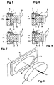
- the figures each show details of brakes in use the invention.
- the brakes can be caliper disc brakes, act in particular sliding caliper disc brakes.
- Fig. 1 shows a plate-shaped, parallel to one Brake disc center plane S extending lining carrier 1 with an opening 3 into which a brake pad 2 of the same contour is inserted in such a way that it emerges on both sides from the lining carrier 1 protrudes, although it is not yet fully assembled still along a displacement axis A with respect the lining carrier 1 is displaceable.
- 2 is the Brake pad 2 moved together with the pad carrier 1 if an application force Fz acts on the brake pad 2.
- Fz application force exerted by a saddle part 4 presses the brake pad 2 against a brake disc 7, whereby it because of the system not only the brake pad 2, but also the Pad carrier 1 synchronized with the brake pad 2 against the brake disc 7 moves.
- Figures 3 u. 4 show an embodiment in which more than just one brake pad 2, namely three brake pads in openings 3 of a lining carrier 1 are held.
- the figures show round openings and cylindrical brake pads with circular Cross-section.
- Shape other shapes and contours individually or in Combination are possible if this should be necessary.
- a brake pad 2 with kidney-shaped External contour shown, which is also kidney-shaped Through opening 3 is to be inserted. This shape corresponds the rotary movement of the brake disc 7.
- the covering carrier 1 each by means of a screw 5 on the saddle part 4 held. Since the saddle part 4 serves to counter the covering 2 To move the brake disc 7 (and back) is in the versions a complete synchronization according to FIGS. 5 to 8 the movements of the lining carrier 1 on the one hand and the Brake pad 2 realized on the other hand.
- the Figures 5 u. 7 is in Figures 6 u. 8 provided that the Pad carrier 1 with its side facing away from the brake disc 7 does not rest on the saddle part 4, but that between the Saddle part 4 and the lining carrier 1 is a distance B. Act it is at the through opening in the lining carrier 1, through which the screw 5 is screwed into the saddle part 4 is to e.g. a slot, the distance B can be accordingly the wear of the brake pad 2 can be changed, especially shortened.
- the function of the disc brake according to the invention results itself from the above description of the exemplary embodiments.
- the assembly / disassembly of the brake pad 2 or more Brake pads in the corresponding openings 3 of the pad carrier 1 is very easy. A simple push into the opening 3 is enough. Is the caliper part 4 when installing the brake pad 2 far enough from the brake disc 7, the brake pad 2 in the brake from the side facing the brake disc of the brake pad 1 are inserted here. If sufficient If there is space, the brake pad 2 can also be in the brake from the side facing away from the brake disc. However, if, for example, tight installation conditions are required make, the lining carrier 1 is removed and the Brake pad 2 is exchanged outside the brake. In one In such a case, the brake pad 2 can of course both from the disc facing away from the brake disc facing Inserted into the lining carrier 1 become.
Landscapes
- Engineering & Computer Science (AREA)
- General Engineering & Computer Science (AREA)
- Mechanical Engineering (AREA)
- Braking Arrangements (AREA)
Applications Claiming Priority (2)
| Application Number | Priority Date | Filing Date | Title |
|---|---|---|---|
| DE19936394A DE19936394B4 (de) | 1999-08-03 | 1999-08-03 | Scheibenbremse |
| DE19936394 | 1999-08-03 |
Publications (2)
| Publication Number | Publication Date |
|---|---|
| EP1074756A2 true EP1074756A2 (fr) | 2001-02-07 |
| EP1074756A3 EP1074756A3 (fr) | 2001-07-04 |
Family
ID=7916948
Family Applications (1)
| Application Number | Title | Priority Date | Filing Date |
|---|---|---|---|
| EP00116542A Withdrawn EP1074756A3 (fr) | 1999-08-03 | 2000-07-31 | Frein à disque |
Country Status (2)
| Country | Link |
|---|---|
| EP (1) | EP1074756A3 (fr) |
| DE (1) | DE19936394B4 (fr) |
Cited By (3)
| Publication number | Priority date | Publication date | Assignee | Title |
|---|---|---|---|---|
| EP1701055A1 (fr) * | 2005-03-10 | 2006-09-13 | Robert Bosch Gmbh | Plaquette pour disque à auto-serrage |
| JP2011117612A (ja) * | 2006-10-25 | 2011-06-16 | Akebono Brake Ind Co Ltd | ディスクブレーキ用摩擦パッド組立て体 |
| CN107117138A (zh) * | 2017-05-25 | 2017-09-01 | 四川瑞丰锻造有限公司 | 一种汽车刹车装置 |
Families Citing this family (2)
| Publication number | Priority date | Publication date | Assignee | Title |
|---|---|---|---|---|
| DE10038490A1 (de) * | 2000-08-08 | 2002-02-21 | Wabco Gmbh & Co Ohg | Vollscheibenbremse für Straßenfahrzeuge |
| AT523549A1 (de) * | 2020-03-13 | 2021-09-15 | Greenbrakes Gmbh | Elektromechanische bremsenanlage |
Citations (4)
| Publication number | Priority date | Publication date | Assignee | Title |
|---|---|---|---|---|
| DE1887149U (de) | 1964-02-06 | Alfred Teves Maschinen- und Armaturenfabrik K.G., Frankfurt/M | Teilbelagscheibenbremse | |
| DE1242107B (de) | 1964-12-31 | 1967-06-08 | Daimler Benz Ag | Teilbelag-Scheibenbremse fuer Fahrzeuge, insbesondere Kraftfahrzeuge |
| DE3906450A1 (de) | 1989-03-01 | 1990-09-06 | Kraft Paul | Traegerplatte fuer bremsbelaege |
| DE4220630C1 (de) | 1992-06-24 | 1993-12-09 | Daimler Benz Ag | Bremsbacke für eine Teilbelag-Scheibenbremse |
Family Cites Families (7)
| Publication number | Priority date | Publication date | Assignee | Title |
|---|---|---|---|---|
| DE1126261B (de) * | 1960-08-24 | 1962-03-22 | Teves Kg Alfred | Teilbelagscheibenbremse, insbesondere fuer Kraftfahrzeuge |
| DE1625679B1 (de) * | 1967-09-23 | 1970-06-25 | Bergische Stahlindustrie | Halterung fuer eine Bremsbacke einer Teilbelagscheibenbremse |
| DE3317913A1 (de) * | 1983-05-17 | 1984-11-22 | Knorr-Bremse GmbH, 8000 München | Bremsbelagtraeger fuer teilbelag-scheibenbremsen |
| DE4301006C2 (de) * | 1993-01-18 | 1997-06-05 | Becorit Grubenausbau Gmbh | Bremsbelag für Teilbelag- oder Vollbelag-Scheibenbremsen |
| DE9300651U1 (de) * | 1993-01-20 | 1993-03-11 | Industrievertretungen I. Brune, 4902 Bad Salzuflen | Kunststoff-Weithalsfaß mit abnehmbaren Deckel |
| DE9307017U1 (de) * | 1993-05-08 | 1993-07-15 | Jurid Werke Gmbh, 2056 Glinde | Bremsbelag für Scheibenbremsen |
| DE19823016C1 (de) * | 1998-05-22 | 1999-12-02 | Wabco Perrot Bremsen Gmbh | Scheibenbremse für ein Landfahrzeug |
-
1999
- 1999-08-03 DE DE19936394A patent/DE19936394B4/de not_active Expired - Fee Related
-
2000
- 2000-07-31 EP EP00116542A patent/EP1074756A3/fr not_active Withdrawn
Patent Citations (4)
| Publication number | Priority date | Publication date | Assignee | Title |
|---|---|---|---|---|
| DE1887149U (de) | 1964-02-06 | Alfred Teves Maschinen- und Armaturenfabrik K.G., Frankfurt/M | Teilbelagscheibenbremse | |
| DE1242107B (de) | 1964-12-31 | 1967-06-08 | Daimler Benz Ag | Teilbelag-Scheibenbremse fuer Fahrzeuge, insbesondere Kraftfahrzeuge |
| DE3906450A1 (de) | 1989-03-01 | 1990-09-06 | Kraft Paul | Traegerplatte fuer bremsbelaege |
| DE4220630C1 (de) | 1992-06-24 | 1993-12-09 | Daimler Benz Ag | Bremsbacke für eine Teilbelag-Scheibenbremse |
Cited By (5)
| Publication number | Priority date | Publication date | Assignee | Title |
|---|---|---|---|---|
| EP1701055A1 (fr) * | 2005-03-10 | 2006-09-13 | Robert Bosch Gmbh | Plaquette pour disque à auto-serrage |
| JP2006250353A (ja) * | 2005-03-10 | 2006-09-21 | Robert Bosch Gmbh | 自己倍力式のディスクブレーキに用いられる摩擦ブレーキライニングおよび自己倍力式のディスクブレーキ |
| JP2011117612A (ja) * | 2006-10-25 | 2011-06-16 | Akebono Brake Ind Co Ltd | ディスクブレーキ用摩擦パッド組立て体 |
| CN107117138A (zh) * | 2017-05-25 | 2017-09-01 | 四川瑞丰锻造有限公司 | 一种汽车刹车装置 |
| CN107117138B (zh) * | 2017-05-25 | 2023-10-24 | 四川瑞丰锻造有限公司 | 一种汽车刹车装置 |
Also Published As
| Publication number | Publication date |
|---|---|
| DE19936394B4 (de) | 2004-07-29 |
| EP1074756A3 (fr) | 2001-07-04 |
| DE19936394A1 (de) | 2001-03-15 |
Similar Documents
| Publication | Publication Date | Title |
|---|---|---|
| EP2997278B2 (fr) | Frein à disque à étrier d'un véhicule | |
| DE3919179C2 (fr) | ||
| EP2997277B1 (fr) | Frein à disque à étrier d'un véhicule, en particulier d'un véhicule utilitaire, et ressort de retenue d'un tel frein | |
| DE2822379B2 (de) | Bremsscheibe für Scheibenbremsen, insbesondere Fahrzeugbremsen | |
| DE10260597B4 (de) | Bremsmechanismus für eine Scheibenbremse | |
| DE2334553C3 (de) | Abstützung für die Bremsbacken einer Teilbelag-Scheibenbremse | |
| DE102020216606A1 (de) | Sattelbremse | |
| DE2648750C3 (de) | Drehverstellbarer Stempel | |
| EP1530686A1 (fr) | Frein a disque comportant au moins deux bagues de friction | |
| DE2636442A1 (de) | Scheibenbremse | |
| DE3429728A1 (de) | Bremssattelvorrichtung fuer scheibenbremsen | |
| DE19936394B4 (de) | Scheibenbremse | |
| DE10330633A1 (de) | Pneumatisch oder elektromotorisch betätigbare Scheibenbremse | |
| DE2931071A1 (de) | Kombinierte bremsbackenhalte-spreizfeder | |
| DE19823016C1 (de) | Scheibenbremse für ein Landfahrzeug | |
| DE2745327C3 (de) | Teilbelagscheibenbremse | |
| DE2653861A1 (de) | Scheibenbremse | |
| DE19823034C1 (de) | Scheibenbremse für ein Landfahrzeug | |
| DE2636444A1 (de) | Scheibenbremse mit verschieblich gelagertem bremssattel | |
| DE3232759A1 (de) | Teilbelag-scheibenbremse | |
| DE69407500T2 (de) | Endstück für einen Reibbelagverschleisssensor, insbesondere für Bremsbeläge | |
| DE3022262C2 (fr) | ||
| DE102005052434B4 (de) | Scheibenbremse, insbesondere für ein Nutzfahrzeug | |
| DE19706298B4 (de) | Betätigungsvorrichtung für eine Scheibenbremse, Verdrehsicherungselement und Scheibenbremse mit einer derartigen Betätigungsvorrichtung | |
| DE2439113A1 (de) | Scheibenbremse |
Legal Events
| Date | Code | Title | Description |
|---|---|---|---|
| PUAI | Public reference made under article 153(3) epc to a published international application that has entered the european phase |
Free format text: ORIGINAL CODE: 0009012 |
|
| AK | Designated contracting states |
Kind code of ref document: A2 Designated state(s): DE FR GB IT SE |
|
| AX | Request for extension of the european patent |
Free format text: AL;LT;LV;MK;RO;SI |
|
| PUAL | Search report despatched |
Free format text: ORIGINAL CODE: 0009013 |
|
| AK | Designated contracting states |
Kind code of ref document: A3 Designated state(s): AT BE CH CY DE DK ES FI FR GB GR IE IT LI LU MC NL PT SE |
|
| AX | Request for extension of the european patent |
Free format text: AL;LT;LV;MK;RO;SI |
|
| 17P | Request for examination filed |
Effective date: 20011213 |
|
| AKX | Designation fees paid |
Free format text: DE FR GB IT SE |
|
| STAA | Information on the status of an ep patent application or granted ep patent |
Free format text: STATUS: THE APPLICATION IS DEEMED TO BE WITHDRAWN |
|
| 18D | Application deemed to be withdrawn |
Effective date: 20060801 |