EP1074854A1 - Verfahren zum Messen der Entfernung eines Objekts - Google Patents
Verfahren zum Messen der Entfernung eines Objekts Download PDFInfo
- Publication number
- EP1074854A1 EP1074854A1 EP99830509A EP99830509A EP1074854A1 EP 1074854 A1 EP1074854 A1 EP 1074854A1 EP 99830509 A EP99830509 A EP 99830509A EP 99830509 A EP99830509 A EP 99830509A EP 1074854 A1 EP1074854 A1 EP 1074854A1
- Authority
- EP
- European Patent Office
- Prior art keywords
- distance
- signal
- prefixed
- sample
- scanning line
- Prior art date
- Legal status (The legal status is an assumption and is not a legal conclusion. Google has not performed a legal analysis and makes no representation as to the accuracy of the status listed.)
- Withdrawn
Links
Images

Classifications
-
- G—PHYSICS
- G01—MEASURING; TESTING
- G01S—RADIO DIRECTION-FINDING; RADIO NAVIGATION; DETERMINING DISTANCE OR VELOCITY BY USE OF RADIO WAVES; LOCATING OR PRESENCE-DETECTING BY USE OF THE REFLECTION OR RERADIATION OF RADIO WAVES; ANALOGOUS ARRANGEMENTS USING OTHER WAVES
- G01S17/00—Systems using the reflection or reradiation of electromagnetic waves other than radio waves, e.g. lidar systems
- G01S17/02—Systems using the reflection of electromagnetic waves other than radio waves
- G01S17/06—Systems determining position data of a target
- G01S17/08—Systems determining position data of a target for measuring distance only
- G01S17/32—Systems determining position data of a target for measuring distance only using transmission of continuous waves, whether amplitude-, frequency-, or phase-modulated, or unmodulated
- G01S17/36—Systems determining position data of a target for measuring distance only using transmission of continuous waves, whether amplitude-, frequency-, or phase-modulated, or unmodulated with phase comparison between the received signal and the contemporaneously transmitted signal
-
- G—PHYSICS
- G01—MEASURING; TESTING
- G01S—RADIO DIRECTION-FINDING; RADIO NAVIGATION; DETERMINING DISTANCE OR VELOCITY BY USE OF RADIO WAVES; LOCATING OR PRESENCE-DETECTING BY USE OF THE REFLECTION OR RERADIATION OF RADIO WAVES; ANALOGOUS ARRANGEMENTS USING OTHER WAVES
- G01S7/00—Details of systems according to groups G01S13/00, G01S15/00, G01S17/00
- G01S7/48—Details of systems according to groups G01S13/00, G01S15/00, G01S17/00 of systems according to group G01S17/00
- G01S7/497—Means for monitoring or calibrating
Definitions
- the present invention relates to a method for measuring the distance of an object.
- the method of the present invention is carried out through an optical device for measuring the distance, which among the other things, is also able to read an optical code placed on the object.
- the measurement of the distance of an object is very useful, if not in some cases, essential.
- all the mechanical machining where it is necessary to know the distance from the machine of the surface to be machined so as to position the tools correctly and/or to program the machine correctly, or all those cases in which knowing the distance parameter allows setting up instruments for the process optimization (for example, in the optics and photography fields, where the distance parameter is strictly connected to focusing issues).
- the measurement of the distance of an object is often required in handling plants for the delivery and sorting of objects, where it is required to identify and classify objects having very different sizes, and to carry out an automatic measurement of the dimensions of objects, so as to accelerate and optimize the further stages of delivery and storage of the same.
- these plants are provided with a conveyor belt on which the objects to be identified and sorted are placed, and with one or more optical devices, generally of the laser-light emission type (commonly referred to as laser scanner) intended for carrying out the reading of the optical codes and the measurement of the object dimensions.
- optical devices generally of the laser-light emission type (commonly referred to as laser scanner) intended for carrying out the reading of the optical codes and the measurement of the object dimensions.
- knowing the distance parameter is useful on the one side to correctly focus the emission laser beam on the object to be scanned so as to make a correct reading of the optical code present on the object itself, and on the other side to determine the height of the latter and consequently, for example, its dimensions and/or volume.
- knowing the distance parameter in real time advantageously allows the adjustment of the operating parameters of the electronic circuits present in the scanner, so as to set prefixed operating configurations in the scanner itself.
- the European patent application No. 0 652 530 describes a laser scanner having a high-frequency modulated laser-light emission wherein the distance of the object is obtained by the phase difference between the signal emitted by the scanner and the signal received.
- the scanner comprises a source of emission of amplitude-modulated laser light by a local oscillator; means of optical scanning to direct the laser light towards the object to be scanned, and light-receiving means to collect the light diffused by the illuminated object and generate an electric signal proportional to the intensity of the light diffused.
- the signal generated by the light-receiving means is transmitted to a phase demodulator, which also receives a signal from the local oscillator; the demodulator measures a phase difference between the above indicated two signals and generates an electric signal proportional to said phase difference. Finally, suitable calculating means processes this electric signal so as to calculate a distance value based on the above phase difference.
- offset of the signal refers to a position error on the plane of the phase/distance transfer function.
- the measurement of the distance requires the knowledge of parameters A, A 0 and ⁇ 0 , and of the phase ⁇ of the response signal generated by the phase demodulator.
- the electronic components of the device introduce uncontrollable variations in the transfer function with the temperature, and thus, in the phase of the response signal at the output of the phase demodulator.
- pulse devices do not specifically suffer the previously listed drawbacks, they suffer from problems implying intrinsic errors of precision and repeatability, assessable in the order of ⁇ 5 cm, thus being particularly adapted for measuring the distance of large objects and with quite extended scanning areas.
- the technical problem at the basis of the present invention is to carry out a simple and reliable measurement of the distance, that is to provide for a reliable distance measurement which is not influenced by the intrinsic non-linearity of the system.
- the present invention relates to a method for measuring the distance of an object from a measuring device, comprising the following steps:
- the method of the invention comprises a calibration step that is carried out before the distance measurement steps.
- Said calibration step is assigned to associate a prefixed distance value to a prefixed value of a comparison signal representing a prefixed point of the scanning line, when it is positioned at the prefixed distance from the measuring optical device.
- the measurement of the distance of an object consists in detecting the signal diffused by the object. To this signal is associated the distance value that, in the previous calibration step, had been associated to the same value of the signal.
- the method of the invention can be easily carried out and is highly reliable, since the distance measurement does not require operations which are left to the operator's sensitivity (such as those above mentioned of visual observation and comparison of the phase response curve), and because said measure is insensitive to the intrinsic non-linearity of the system.
- the method of the invention allows to measure the distance of a single point of the object and it can be carried out by any conventional optical device implemented with suitable means of calculation for effecting the calibration and distance measurement steps according to the present invention.
- the method of the invention further comprises the following steps:
- the emitted signal is a light beam adapted to illuminate the object along an emission optical path and the detected signal is an analogue electric signal proportional to the luminous image diffused by the object along a receiving optical path.
- the method of the present invention comprises the following steps:
- the calibration step is assigned to identify the numerical value generated by the analogue to digital converter for a prefixed sample representative of a prefixed point on the scanning line, when the latter is placed at a predetermined distance from the measuring optical device. Then, the distance measurement of an object consists in detecting the numerical value of the electric signal and obtaining, by this numerical value, the distance value which, in the previous calibration step, had been associated to the same numerical value and to the same sample.
- the calibration step is carried out during the manufacturing process of the measuring device, and it can be periodically repeated so as to consider any possible changes in the parameters of the device itself during operation.
- the method of the invention comprises the additional step h) of storing the distance value obtained for sample x k in step g1) and iteratively repeating the previous steps starting from step d1) for each further sample x k+1 .
- step h) of storing the distance value obtained for sample x k in step g1) and iteratively repeating the previous steps starting from step d1) for each further sample x k+1 .
- the calibration step comprises the following steps:
- the calibration step is effected by carrying out at least one scan, along a respective scanning line, on a surface of known reflectance (for example a white surface) which is subsequently placed at various prefixed distances.
- a surface of known reflectance for example a white surface
- the light diffused by the surface of known reflectance contains only information relating to the distance of the various points of the scanning line. It is thus possible to calibrate the measuring device so as to measure correctly, afterwards, the distance of any object, independently of its reflectance.
- the execution of a calibration step as that described above advantageously allows to compensate the various differences existing among the devices (for example, the various devices may differ for the positioning of the laser scanning beam), the possible non-linearity of the response given by the demodulator, and the differences, existing among the devices, in the speed profile and, thus, in the distance travelled in a prefixed time interval by the point generating the scan.
- the execution of the above described calibration step allows effecting an easy and reliable distance measurement also when the measuring device is placed transversely, or with a certain inclination, with respect to the object of which the distance is being measured.
- the calibration step further comprises the following steps:
- the method of the invention further comprises the following steps:
- the mean scan is obtained by calculating the arithmetical mean, or any other type of mean, of the numerical values obtained for each sample x j in the various operations of scanning carried out. In this way, it is possible to increase the reliability of the calibration effected and, consequently, of the distance measurement.
- the calibration step further comprises the step of filling with the distance values associated to the numerical values obtained for the samples x j , the items of a calibration matrix having, as index of column j a number from zero to the number of samples x j extracted, and as index of row i, a number from zero to the maximum value of the numerical value obtained after the analogue to digital conversion of the signal.
- the calibration step generates a calibration matrix in which each item (i, j) of the matrix contains the distance value of the point of the scanning line which provides, for the sample x j , the numerical value of phase response i.
- each item (i, j) of the matrix contains the distance value of the point of the scanning line which provides, for the sample x j , the numerical value of phase response i.
- the method of the present invention further comprises the step of providing the matrix with a number of items (i, j) higher than the number of samples x j , and filling the empty items (i, j) of the matrix.
- the step of filling the empty items (i, j) of the matrix comprises the step of locating, column by column, the empty items (i, j) of the matrix and filling each of these empty items with a value obtained by linearly interpolating between the two numerical values differing from 0 that are nearer to the empty item, and belonging to the same column. In this way, it is possible to obtain a calibration matrix that is complete in all its items, so as to go on to the following steps of distance measurement.
- the measuring optical devices carry out a sampling of the scanning at regular time intervals, to which not necessarily correspond regular space intervals of the point generating the scan.
- This is essentially due to the particular speed profile which the point generating the scan has, this profile depending, for example, on the rotor geometry, on the impact point of the luminous spot on the rotor mirror, and on the dimensions of the spot.
- These parameters are not easily controllable, which is why all devices can have differences in the speed profile and thus, in the space covered in a prefixed time interval.
- the method of the present invention comprises the step of associating to said at least one sample x j a respective linear position on the scanning line.
- this step comprises the following steps:
- the method of the present invention further comprises the step of reading an optical code placed on the object.
- the electric signal generated by the light-sensitive means besides being used to measure the distance of a point of the object, or more distances on a surface of the object, is processed by suitable processing means to allow carrying out the reading of an optical code placed on the object.
- optical code refers to a code (such as, for example, a bar code, a two-dimensional code, and the like) adapted to univocally identify the objects on which it is provided.
- the reading of the optical code is carried out by using the same device used for measuring the distance.
- it comprises an amplitude demodulator, a digitizer and a decoder.
- the distance information or the dimensions or volume information
- other information of identifications reported on the optical code such as type of product, manufacturer, price, place of origin, destination, etc.
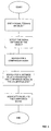
- the method of the invention allows to carry out a reliable measurement of the distance of an object thanks to the realization of a calibration step, which is effected before the steps for measuring the distance, and it is intended to associate a prefixed distance value to a prefixed value of a comparison signal representative of a prefixed point on the scanning line, when the latter is positioned at the prefixed distance from the measuring optical device.
- the measurement of the distance of an object afterwards consists in detecting the signal diffused by the object. This signal is associated to the distance value that had been associated to the same value of the signal in the previous calibration step.
- At least one scan on the object is carried out by a light beam adapted to illuminate the object along an emission optical path; the detected signal is therefore an analogue electric signal proportional to the luminous image diffused by the object along a receiving optical path.
- the calibration step consists in identifying the numerical value generated by the analogue-to-digital converter for a plurality of samples representative of respective points on the scanning line when the latter is placed at a predetermined distance from the measuring optical device.
- the measurement of the distance of an object consists then in detecting the light diffused by the object and obtaining, for each sample, a numerical value by the analogue-to-digital converter. To this numerical value is then associated the distance value which had been associated to the same numerical value and to the same sample in the previous calibration step.
- the method of the invention can be carried out by any conventional optical device, such as that described in the European patent application No. 0 652 530 by the same Applicant (of which the device of the invention is an improved embodiment), implemented with suitable means of calculation for the realization of the calibration and distance measurement steps according to the present invention.
- the description of the method of the invention is made starting from the description of the calibration step which, as already said, is carried out during the manufacturing process of the measuring optical device, and which can be repeated over the time so as to consider possible changes in the parameters of the device during operation.
- the calibration step consists in placing a surface of known and constant reflectance (for example a white plane) covering the entire scanning generated by the device, in front of the measuring device, at a prefixed distance D.
- the sampled analogue signal is then converted into digital signal so as to obtain a numerical value for each sample x j .
- the prefixed distance value at which the white surface has been placed is associated with the previous steps, and the previous steps are iteratively repeated for a prefixed number of times, each time moving the white surface by a prefixed distance interval ⁇ D (for example, 5 cm) from the Dmax to the Dmin.
- ⁇ D for example, 5 cm
- the process can also be inverted, that is, starting from the minimum distance Dmin and moving each time the white surface by a distance interval ⁇ D from the minimum distance Dmin to the maximum distance Dmax.
- a plurality of scans of the white surface are carried out along the scanning line (when the object is not in motion with respect to the measuring device) or along respective scanning lines (when the object is moving with respect to the measuring device, as for example when it is positioned on a conveyor belt).
- a mean scan is then extracted by the plurality of scans carried out, and it is then processed so as to obtain, for each sample of the mean scan, a numerical value to which a distance value is associated.
- the mean scan is obtained by making an arithmetical mean of the numerical values obtained for each sample x j in the various operations of scanning effected.
- mean any type of mean (geometric, quadratic, ponderal, etc.) to obtain the mean scan.
- the mean scan (by arithmetical mean) will have the following values: Mean scan 10 12 12 13 13
- the association of the distance values to the numerical values in the calibration step of the method of the present invention is made by filling the items of a calibration matrix having as index of column j a number from zero to the number of samples x j extracted (for example, 200), and as index of row i, a number from zero to the maximum value of the numerical value obtained after the analogue to digital conversion of the signal (which, in the specific example of the present invention is an 8-bit signal, and therefore the maximum value is 255).
- a linear interpolation is effected column by column as follows: column by column, the empty items (i, j) of the matrix are located; each located empty item is then filled with a numerical value which is obtained by linearly interpolating between the two numerical values differing from 0 that are nearer to the empty item in question, and belonging to the same column.
- the left column will become as the right one: 10 10 0 13 0 16 20 20 0 25 0 30 35 35 0 53 0 71 90 90
- the possibility of increasing the precision of the reticule of distances in height can be particularly advantageous when the calibration matrix is required to be continuously updated in real time so as to recover the intrinsic non-linearity of the system and the changes in the response of the system caused by the change in the environmental conditions.
- the response of the system can change too.
- the data read from the calibration matrix will change, too, and it will not reflect the new operating situation. Therefore, it is possible to update the matrix by frequently effecting some "simplified" calibrations, which consist in illuminating some reference means having known reflectance, placed at known distances (inside or outside the measuring device), and carrying out a limited number of distance measurements on said reference means.
- the calibration step brings to the generation of a calibration matrix in which each item (i, j) of the matrix contains the distance value of the point of the scanning line which provides, for the sample j, the numerical value of phase response i. This matrix is then used during the steps for measuring the distance of an object.
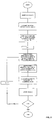
- the method for measuring the distance comprises the starting steps of carrying out a plurality of scans of the object along at least one scanning line and, for each scan carried out, acquiring an analogue electric signal representative of the luminous image diffused by the object along the scanning line.
- the sampled analogue signal is then converted into digital signal so as to obtain a numerical value k for each sample x k .
- the distance so obtained is then stored in a table, and the previous steps are iteratively repeated for each further sample x k+1 so as to obtain the distance profile of the object. This allows to obtain information on the dimensions of the object and on its volume too.
- the method of the invention also comprises a step in which each sample x j is associated to a respective linear position on the scanning line.
- the sampling of the scan is effected at regular time intervals, to which not necessarily correspond regular space intervals of the point generating the scan. This is due to the fact that the speed of the point generating the scan (spot) may not be constant from the beginning to the end of the scan itself.
- a grid composed of alternated white and black equally-spaced intervals (for example 1 cm) having known dimension is positioned along the scanning line, at a prefixed distance D.
- the reflectance signal diffused by the grid is acquired, thus detecting the sequence of black and white intervals as time intervals, and storing each time, in an item of a calibration table, the time needed to travel each interval of the grid.
- each item shows the time needed to cover the single white or black intervals of the grid used for the calibration and, once the time interval needed to move from a sample to the other (sampling period) is known, it is possible to obtain the instant T j in which a certain sample j is generated (by multiplying j by the sampling period).
- the number of items summed up gives the distance, for example in centimeters, of the sample j from the scan starting point on the scanning line.
- This step which is adapted to create a univocal association between the number of the sample and its position along the scanning line at a prefixed distance, is carried out once and then it is stored in the non volatile memory of the device. It must be noted that, if more samples fall within the same centimeter, a higher resolution will be obtained.
- the sample-centimeter association is memorized for a prefixed distance D. Nevertheless, it is possible to obtain it for any distance from the measuring device by using common trigonometric formulas.
- the method of the present invention advantageously allows obtaining, for each sample of the scanning line, its height and position along the scanning line.
- the position of the samples on the advancement axis of the conveyor belt can be measured through traditional methods (encoder, or a priori knowledge of the transport speed).
- the method of the present invention also allows measuring the distance of a single point of the object from the measuring device, still having all the above advantages. In this case, it is not necessary to generate any scan (a fixed laser beam being enough), and it is not necessary to effect the sampling of the signal (since in the distance measurement step there is a single value of electric signal). In addition, by using some light-receiving devices for the luminous signal, such as some light-resistors or C-MOS sensors (which already provide a digital signal), the digitization of the analogue signal is not required, either.
- the method of the present invention also comprises the step of reading an optical code placed on the object, so as to associate the distance information (or the dimensions, or volume information) to other information of identifications reported on the optical code, such as type of product, manufacturer, price, place of origin, destination, etc.
- the electric signal generated by the detecting means is processed by suitable elaborating means to allow effecting the reading of an optical code placed on the object.
Landscapes
- Engineering & Computer Science (AREA)
- Physics & Mathematics (AREA)
- Computer Networks & Wireless Communication (AREA)
- General Physics & Mathematics (AREA)
- Radar, Positioning & Navigation (AREA)
- Remote Sensing (AREA)
- Electromagnetism (AREA)
- Length Measuring Devices By Optical Means (AREA)
- Measurement Of Optical Distance (AREA)
Priority Applications (2)
| Application Number | Priority Date | Filing Date | Title |
|---|---|---|---|
| EP99830509A EP1074854A1 (de) | 1999-08-04 | 1999-08-04 | Verfahren zum Messen der Entfernung eines Objekts |
| US09/437,469 US7161685B1 (en) | 1999-08-04 | 1999-11-10 | Method for measuring the distance of an object |
Applications Claiming Priority (1)
| Application Number | Priority Date | Filing Date | Title |
|---|---|---|---|
| EP99830509A EP1074854A1 (de) | 1999-08-04 | 1999-08-04 | Verfahren zum Messen der Entfernung eines Objekts |
Publications (1)
| Publication Number | Publication Date |
|---|---|
| EP1074854A1 true EP1074854A1 (de) | 2001-02-07 |
Family
ID=8243543
Family Applications (1)
| Application Number | Title | Priority Date | Filing Date |
|---|---|---|---|
| EP99830509A Withdrawn EP1074854A1 (de) | 1999-08-04 | 1999-08-04 | Verfahren zum Messen der Entfernung eines Objekts |
Country Status (2)
| Country | Link |
|---|---|
| US (1) | US7161685B1 (de) |
| EP (1) | EP1074854A1 (de) |
Cited By (6)
| Publication number | Priority date | Publication date | Assignee | Title |
|---|---|---|---|---|
| EP1840593A1 (de) * | 2006-03-29 | 2007-10-03 | Leica Geosystems AG | Kalibrierbarer Entfernungsmesser und Verfahren zum kalibrieren eines Solchen |
| EP1890167A1 (de) * | 2006-08-17 | 2008-02-20 | Delphi Technologies, Inc. | Verfahren und Vorrichtung zum Kalibrieren eines gepulsten Systems |
| US8413902B2 (en) | 2007-09-07 | 2013-04-09 | Datalogic Scanning Group S.R.L. | Image acquisition device and optical component thereof |
| CN113267785A (zh) * | 2020-02-17 | 2021-08-17 | 北京小米移动软件有限公司 | 距离检测方法及装置、电子设备 |
| US20210263151A1 (en) * | 2018-05-09 | 2021-08-26 | Dalhouse University | Systems and methods of sparse orthogonal diverging wave ultrasound imaging |
| CN114509776A (zh) * | 2022-04-08 | 2022-05-17 | 探维科技(北京)有限公司 | 硬件级图像融合系统的同步测量装置、方法、设备及介质 |
Families Citing this family (2)
| Publication number | Priority date | Publication date | Assignee | Title |
|---|---|---|---|---|
| US20020014533A1 (en) * | 1995-12-18 | 2002-02-07 | Xiaxun Zhu | Automated object dimensioning system employing contour tracing, vertice detection, and forner point detection and reduction methods on 2-d range data maps |
| CN102142142A (zh) * | 2010-01-29 | 2011-08-03 | 鸿富锦精密工业(深圳)有限公司 | 产品轮廓制程能力验证系统及方法 |
Citations (5)
| Publication number | Priority date | Publication date | Assignee | Title |
|---|---|---|---|---|
| US5006721A (en) * | 1990-03-23 | 1991-04-09 | Perceptron, Inc. | Lidar scanning system |
| EP0652530A2 (de) * | 1993-11-04 | 1995-05-10 | Datalogic S.P.A. | Laserleser zum Lesen von Zeichen mit verschiedenen Reflexionen, insbesondere von Streichkoden |
| US5696516A (en) * | 1996-06-28 | 1997-12-09 | Hughes Electronics | Radar system and accurate method of range resolution |
| US5739901A (en) * | 1995-05-12 | 1998-04-14 | Mitsubishi Denki Kabushiki Kaisha | Distance measuring apparatus and distance measuring method for a vehicle |
| US5867125A (en) * | 1995-12-20 | 1999-02-02 | Cluff; Larry A. | Incremental phase and distance measurement through digital phase signature comparison |
Family Cites Families (2)
| Publication number | Priority date | Publication date | Assignee | Title |
|---|---|---|---|---|
| EP0946855B1 (de) * | 1996-12-23 | 2001-10-17 | Ruprecht-Karls-Universität Heidelberg | Verfahren und vorrichtungen zur distanzmessung zwischen objektstrukturen |
| FR2761151B1 (fr) * | 1997-03-21 | 1999-07-16 | Samuel Bucourt | Systeme optronique de mesure de distance sans contact d'une source lumineuse par analyse de la courbure du point d'onde issu de celle-ci |
-
1999
- 1999-08-04 EP EP99830509A patent/EP1074854A1/de not_active Withdrawn
- 1999-11-10 US US09/437,469 patent/US7161685B1/en not_active Expired - Lifetime
Patent Citations (5)
| Publication number | Priority date | Publication date | Assignee | Title |
|---|---|---|---|---|
| US5006721A (en) * | 1990-03-23 | 1991-04-09 | Perceptron, Inc. | Lidar scanning system |
| EP0652530A2 (de) * | 1993-11-04 | 1995-05-10 | Datalogic S.P.A. | Laserleser zum Lesen von Zeichen mit verschiedenen Reflexionen, insbesondere von Streichkoden |
| US5739901A (en) * | 1995-05-12 | 1998-04-14 | Mitsubishi Denki Kabushiki Kaisha | Distance measuring apparatus and distance measuring method for a vehicle |
| US5867125A (en) * | 1995-12-20 | 1999-02-02 | Cluff; Larry A. | Incremental phase and distance measurement through digital phase signature comparison |
| US5696516A (en) * | 1996-06-28 | 1997-12-09 | Hughes Electronics | Radar system and accurate method of range resolution |
Cited By (9)
| Publication number | Priority date | Publication date | Assignee | Title |
|---|---|---|---|---|
| EP1840593A1 (de) * | 2006-03-29 | 2007-10-03 | Leica Geosystems AG | Kalibrierbarer Entfernungsmesser und Verfahren zum kalibrieren eines Solchen |
| WO2007112829A1 (de) | 2006-03-29 | 2007-10-11 | Leica Geosystems Ag | Kalibrierbarer entfernungsmesser und verfahren zum kalibrieren eines solchen |
| EP1890167A1 (de) * | 2006-08-17 | 2008-02-20 | Delphi Technologies, Inc. | Verfahren und Vorrichtung zum Kalibrieren eines gepulsten Systems |
| US8413902B2 (en) | 2007-09-07 | 2013-04-09 | Datalogic Scanning Group S.R.L. | Image acquisition device and optical component thereof |
| US20210263151A1 (en) * | 2018-05-09 | 2021-08-26 | Dalhouse University | Systems and methods of sparse orthogonal diverging wave ultrasound imaging |
| US11885877B2 (en) * | 2018-05-09 | 2024-01-30 | Dalhousie University | Systems and methods of sparse orthogonal diverging wave ultrasound imaging |
| CN113267785A (zh) * | 2020-02-17 | 2021-08-17 | 北京小米移动软件有限公司 | 距离检测方法及装置、电子设备 |
| CN113267785B (zh) * | 2020-02-17 | 2023-10-13 | 北京小米移动软件有限公司 | 距离检测方法及装置、电子设备 |
| CN114509776A (zh) * | 2022-04-08 | 2022-05-17 | 探维科技(北京)有限公司 | 硬件级图像融合系统的同步测量装置、方法、设备及介质 |
Also Published As
| Publication number | Publication date |
|---|---|
| US7161685B1 (en) | 2007-01-09 |
Similar Documents
| Publication | Publication Date | Title |
|---|---|---|
| US4994677A (en) | Method for positioning an object relative to a plane and measuring length and apparatus for implementing same | |
| US5319442A (en) | Optical inspection probe | |
| US4705395A (en) | Triangulation data integrity | |
| EP0029748B1 (de) | Optisches Messsystem | |
| CN101876534B (zh) | 测量镜面反射表面的相对位置的方法和装置 | |
| EP0047250B1 (de) | Dimensionsmessgerät | |
| EP0206744A2 (de) | Optische Oberflächenfühlvorrichtung | |
| Zámečníková et al. | Influence of surface reflectivity on reflectorless electronic distance measurement and terrestrial laser scanning | |
| US20040233416A1 (en) | Method and device for recording a three-dimensional distance-measuring image | |
| EP1067361A1 (de) | Verfahren und Vorrichtung zur Entfernungsmessung eines Objekts | |
| EP0314520B1 (de) | Gerät zur automatischen Kontrolle des Vergrösserungsfaktors in einem Rasterelektronenmikroskop | |
| WO1996005477A1 (en) | High precision semiconductor component alignment systems | |
| Adams et al. | The interpretation of phase and intensity data from AMCW light detection sensors for reliable ranging | |
| US7161685B1 (en) | Method for measuring the distance of an object | |
| US7602505B2 (en) | Method for the automatic parameterization of measuring systems | |
| US6102291A (en) | Apparatus and process for detecting the presence and encumbrance of an object | |
| JPH07146113A (ja) | レーザ変位計 | |
| US6069984A (en) | Method and apparatus for correcting optical spot position | |
| JP4215220B2 (ja) | 表面検査方法及び表面検査装置 | |
| US5086411A (en) | Optical location systems | |
| US4869110A (en) | Laser strain extensometer for material testing | |
| TW399246B (en) | Method and apparatus for checking shape | |
| CN110476080B (zh) | 用于对扫描角进行扫描并且用于分析处理探测器的激光雷达设备和方法 | |
| KR920004214B1 (ko) | 광학식변위 측정장치 | |
| US5631738A (en) | Laser ranging system having reduced sensitivity to surface defects |
Legal Events
| Date | Code | Title | Description |
|---|---|---|---|
| PUAI | Public reference made under article 153(3) epc to a published international application that has entered the european phase |
Free format text: ORIGINAL CODE: 0009012 |
|
| AK | Designated contracting states |
Kind code of ref document: A1 Designated state(s): AT BE CH CY DE DK ES FI FR GB GR IE IT LI LU MC NL PT SE |
|
| AX | Request for extension of the european patent |
Free format text: AL;LT;LV;MK;RO;SI |
|
| 17P | Request for examination filed |
Effective date: 20010726 |
|
| AKX | Designation fees paid |
Free format text: AT BE CH CY DE DK ES FI FR GB GR IE IT LI LU MC NL PT SE |
|
| 17Q | First examination report despatched |
Effective date: 20070525 |
|
| 18W | Application withdrawn |
Effective date: 20081008 |