EP1074921A2 - Système d'aide aux affaires et support d'enregistrement - Google Patents
Système d'aide aux affaires et support d'enregistrement Download PDFInfo
- Publication number
- EP1074921A2 EP1074921A2 EP00114026A EP00114026A EP1074921A2 EP 1074921 A2 EP1074921 A2 EP 1074921A2 EP 00114026 A EP00114026 A EP 00114026A EP 00114026 A EP00114026 A EP 00114026A EP 1074921 A2 EP1074921 A2 EP 1074921A2
- Authority
- EP
- European Patent Office
- Prior art keywords
- data
- business
- slip
- axis
- worksheet
- Prior art date
- Legal status (The legal status is an assumption and is not a legal conclusion. Google has not performed a legal analysis and makes no representation as to the accuracy of the status listed.)
- Withdrawn
Links
Images


Classifications
-
- G—PHYSICS
- G06—COMPUTING OR CALCULATING; COUNTING
- G06Q—INFORMATION AND COMMUNICATION TECHNOLOGY [ICT] SPECIALLY ADAPTED FOR ADMINISTRATIVE, COMMERCIAL, FINANCIAL, MANAGERIAL OR SUPERVISORY PURPOSES; SYSTEMS OR METHODS SPECIALLY ADAPTED FOR ADMINISTRATIVE, COMMERCIAL, FINANCIAL, MANAGERIAL OR SUPERVISORY PURPOSES, NOT OTHERWISE PROVIDED FOR
- G06Q10/00—Administration; Management
- G06Q10/10—Office automation; Time management
-
- G—PHYSICS
- G06—COMPUTING OR CALCULATING; COUNTING
- G06Q—INFORMATION AND COMMUNICATION TECHNOLOGY [ICT] SPECIALLY ADAPTED FOR ADMINISTRATIVE, COMMERCIAL, FINANCIAL, MANAGERIAL OR SUPERVISORY PURPOSES; SYSTEMS OR METHODS SPECIALLY ADAPTED FOR ADMINISTRATIVE, COMMERCIAL, FINANCIAL, MANAGERIAL OR SUPERVISORY PURPOSES, NOT OTHERWISE PROVIDED FOR
- G06Q10/00—Administration; Management
- G06Q10/06—Resources, workflows, human or project management; Enterprise or organisation planning; Enterprise or organisation modelling
-
- G—PHYSICS
- G06—COMPUTING OR CALCULATING; COUNTING
- G06F—ELECTRIC DIGITAL DATA PROCESSING
- G06F16/00—Information retrieval; Database structures therefor; File system structures therefor
- G06F16/20—Information retrieval; Database structures therefor; File system structures therefor of structured data, e.g. relational data
Definitions
- This invention relates to a business support system and a business support recording medium.
- an object of the present invention to overcome the problem in item (1) by providing a business support system, a business support method, and a business support data recording medium which realize a computer with a large-scale, high-speed totalizing function. Furthermore, it is another object of the present invention to provide a business support system, a business support method, and a business support data recording medium which are highly reliable because the data is compensated for by another computer even if any microcomputer terminal has failed. In addition, it is still another object of the present invention to provide a business support system, a business support method, and a business support data recording medium which enable the past data to be stored immediately, even if a new microcomputer is added to a network.
- the slips or forms that accept the data are designed to understand the meaning or contents of the input data automatically and effect processing.
- FIG. 1A shows a cell having the basic data structure of the present invention.
- the cell is a data access control cell. Although various types of cells are defined in the present invention, one representative cell will be explained.
- the data access control cell is a cell for slips. Using three axes, a data cell explained later can be accessed.
- the slip stored in the address determined by the parameters can be determined. For example, the slip for the goods person c in charge in department b of company a sold in town d can be displayed.
- X-axis parameter X (x1 (), x2 (), x3 (), 7)
- Y-axis parameter Y (y1 (), y2 (), y3 (), 7)
- Z-axis parameter Z (z1 (), z2 (), z3 (), 7)
- G-axis parameter G (... -g2 (), -g1 (), g0(), +g1(), +g2(), ...)
- parameter x0 When parameter x0 is given in the X-axis parameters, a table for areas (including North America, South America, Asia, Europe, and Australia) appears on the display. When a specifying number is entered into () in parameter x1 (), this determines an area. Then, the table for countries in the area (e.g., Asia) appears on the display. Entering a specifying number into () in parameter x2 () determines a country. When a specifying number is entered into () in x3 () determines a state. Similarly, entering suitable specifying numbers into parentheses until a town has been determined.
- a specifying number When a specifying number is entered into () in parameter x1 (), this determines an area. Then, the table for countries in the area (e.g., Asia) appears on the display. Entering a specifying number into () in parameter x2 () determines a country. When a specifying number is entered into () in x3 () determines
- 0 is entered into () in x3 () and in the later parameters.
- the operation of X-axis specification OK causes the selected state at that time to remain unchanged.
- y1 () level classification table (company, association, group) table is displayed as shown in FIG. 2. Then, entering a number or the like into () in y1 () determines a company, association, or group. If a company is specified, the user's own company/other company classification table will be displayed at y2() level of hierarchy. Here, entering a number or the like into () in y2 () determines either the user's own company or another company. Then, the head office/branch office classification table or the branch office classification table is displayed at y3 () level of hierarchy. If the head office is selected, control will proceed to y4 () level of hierarchy and the department classification table is displayed. Entering a specifying number into () in y4 () determines a department. Similarly, entering specifying numbers into the parentheses in y5 (), y6 (), and y7 () determines a person in charge.
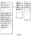
- the types of worksheet e.g., slip
- the worksheet includes various types of slips, totaling sheets and analizing sheets.
- filling-in sheets used in business including various types of slips, ledgers, and forms, and tables, are referred to as worksheets.
- writing a slip code into () in z1() level of hierarchy determines the type of slip
- writing a commodity code into () in z2 () determines the type of slip for a specific commodity.
- the specified slip is a sales slip and the commodity is commodity A for sale
- the sales quantity, unit price, and others will be displayed.
- the sales slip for commodity ⁇ could be displayed on an area basis or a person-in-charge basis.
- a commodity selecting parameter may be specified first and then a slip parameter be specified.
- the above hierarchical structure is used in entering the data when the person in charge sold a commodity. For example, when the person in charge sold a commodity and specified the commodity, the slip table used for the commodity is displayed. When the commodity was sold, the sales slip, order-received slip, amount recoverable slip, sales quantity slip, or the like is selected.
- the period of time is specified. For example, entering a checkmark into () in each of -g2 (), -g1 (), and g0 () specifies from two days ago to today. Entering a checkmark into () in g0 () specifies only today. Entering a checkmark into () in +g3 () specifies a check on the state of the data only three days later. An example of using the G-axis parameters will be explained later.
- the system of the present invention has the above-described data structure and is designed to be able to perform sequential transmission and reception of common data between the head store and a branch store, between the main office and a branch office, or between the main office and each company in the group. The transmission and reception will be described later.
- the information the data access control cell has includes various addresses.
- the address By the address, the real data stored in another data cell can be specified.
- real data can be written into another data cell specified by the address.
- control cell can function as an active header. This is because the control cell includes the address for an update flag explained later and the transmission destination address for the update flag. In a case where many microcomputers employ the method of the present invention, even when only the control cell is taken out from one computer and used in another computer, the real data in another computer can be accessed.
- the transmission of the address for the control cell through communication means enables the real data in the user's computer located at a distant place to be accessed.
- Information on slips used in the present invention enables a date totalizing function to be achieved in the present system. This not only enables consolidated settlement between an affiliated company and the head office or between branch offices but also provides the user with business support.
- FIG. 4 shows a case where a person in charge sold good and entered the data into a worksheet (e.g., a sales slip).
- FIG. 4 shows a sales slip.
- a Z-axis parameter For example, by giving a Z-axis parameter, a selection is made from the slip table of FIG. 3. The selected slip is displayed on the screen, with the items to be filled in being blank.
- the person in charge is specified using a Y-axis parameter, the name of the person in charge is displayed automatically in the person-in-charge field.
- the sales slip is usually used on the day of sale. Thus, the date on that day is written automatically in the sales day.
- the person in charge enters the code for a customer (customer code) or an individual customer indefinite code if the purchaser is an unregistered individual customer. Then, when the commodity code for the sold commodity, the quantity, and the unit price are entered, the sum total of money is displayed.
- the data inputted as described above is stored in an intelligent data cell explained later.
- FIG. 5 shows the relationship between the above-described data access control cell 1000, an intelligent data cell 2000, a cell control section 3000, a display section 4000, and an operator section 5000.
- the display section 4000 is controlled via a display control section, which is omitted in the figure.
- a slip as shown in FIG. 4 appears on the display and enables data about sales work to be inputted.
- a sales slip of FIG. 4 will be explained as a representative example.
- the screen that allows parameters on the X-, Y-, Z-, and G-axes to be entered is caused to appear on the display 4000. From this screen, parameters are entered, thereby supplying the parameters to the control cell 1000 via the cell control section 3000. Then, the control section 1000 specifies the read address in the intelligent data cell 2000 via the cell control section 3000. As a result, the slip screen for the input of the specified data appears on the display 4000.
- the user operates the keyboard in the operator section 5000, writes the necessary data into the slip, and finishes the action. Then, the written data is written into the intelligent data cell via the cell control section 3000.
- the intelligent data cell 2000 includes a region 2001 in which the slip layout image data is stored and a region in which such data items as values and characters to be written in the blank spaces of the slip are stored.
- the control cell 1000 generates data items that also serve as read addresses in the intelligent data cell 2000.
- FIGS. 6 and 7 show an internal processing function provided in the control cell.
- the sales slip is accompanied by the address for storing the amount of money (MT) indicating the total sales, the address for storing the quantity (NT) indicating the total sales, the address for storing the unit price, the address for storing computing expressions, the address for storing the amount of money (Ms) indicating the amount of money the person in charge entered when selling the commodity, the address for storing the quantity (Ns) showing the quantity the person in charge entered when selling the commodities, the address for storing the update flag, and the address for the transmission destination to which the update flag is to be transferred.
- MT amount of money
- NT indicating the total sales
- Ms amount of money
- Ns showing the quantity the person in charge entered when selling the commodities
- the address for storing the update flag the address for the transmission destination to which the update flag is to be transferred.
- the update flag is set to, for example, "1". Then, the following calculations are performed on the amount of money (MT) and quantity (NT) using specified computing expressions: MT ⁇ MT + Ms and NT ⁇ NT + Ns. In this way, the updating process is carried out. After the updating process, the real data in the update flag, amount of money (Ms), and quantity (Ns) are cleared. Then, the update flag is written in the transmission destination (address) previously set.
- the control cell 1000 reads the update flag periodically and, when the update flag is set to "1", it updates the data as described above.
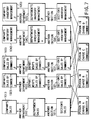
- FIG. 7 shows the relationship between the above-described update flag and the destination to which the update flag is transferred.
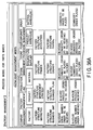
- the destinations to which the update flag for each of the persons in charge A, B, C, and D are the section's sales slip 1011, the section's sales slips 1021, 1031 by commodity, and the section's inventory management slips (ledgers) 1041, 1051.
- the amount of money (MT) from each person in charge is recognized as the amount of money (Ms) and the section's sales (MT) are created.
- the address for the department's sales slip is written as the transmission destination.
- the amount of money (MT) from each section is recognized as the amount of money (Ms) and the department's sales (MT) are created (MT ⁇ MT + Ms).
- the amount of money (MT) from each department is recognized as the amount of money (Ms) and the company's sales (MT) are created (MT ⁇ MT + Ms).
- the route of slips 1021, 1022, 1023 is related to sales slips for commodity ⁇ and creates sales information for each section, for each department, and for each company automatically.
- the route of slips 1031, 1032, 1033 is related to sales slips for commodity ⁇ and creates sales information for each section, for each department, and for each company automatically.
- the route of slips 1041, 1042, 1043 is related to inventory management slips for commodity ⁇ and creates inventory management information for each section, for each department, and for each company automatically.
- the route of slips 1051, 1052, 1053 is related to inventory management slips for commodity ⁇ and creates inventory management information for each section, for each department, and for each company automatically.
- a given computing expression is selected, depending on whether the data input mode or the correction mode is on. In the correction mode, for example, a subtracting process or an adding process is carried out, depending on the contents to be corrected.
- FIG. 6 although computing expressions (1) and (2) are shown as examples, more computing expressions or checking processes may be used. As the number of transmission destinations increases, the update flags are increased in number accordingly.
- FIG. 8 shows the route of sales slips 1011 and 1021 in further detail. When the person in charge has entered data into a sales slip, the information is transmitted to the section's sales slip. In the section's sales slip 1011, storage locations for the amount of money (Ms) are provided for the individual persons in charge A, B, C, and D. In addition, locations for the quantity (Ns) are provided for the persons in charge A, B, C, and D. Moreover, locations for the update flag are provided for the persons in charge A, B, C, and D.
- the update flag "1" is transferred to the update flag transmission destination. Then, in the department's sales slip 1012, the amount of money (MT) and quantity (NT) are updated. The updated information is transmitted to the company's sales slip.
- NT updated stock
- NT existing stock
- Ns sales quantity
- recovery slip information for each section, that for each department, and that for each company are created immediately.
- voucher information for each section, that for each department, and that for each company are created immediately.
- balance sheet information is arranged.
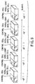
- sets of a data access control cell and an intelligent data cell shown in FIG. 5 are provided on a day-by-day basis as shown in FIG. 9.
- g0 () means the cell on that day
- -g1 () means the cell on the preceding day
- -g2 () means the cell on the day before the preceding day
- +g () means the cell on the following day
- +g2 () means the cell on the day after the following day.
- cells for one year or several years are provided on a day-by-day basis.
- the time when the contents of the data in each cell are fixed as information for one day may be determined in the world reference time. Alternatively, it may be set to any time in each country or each area and the contents of the data in each cell be fixed as information for one day.
- the amount of money in the amount recoverable slip is read on the basis of the recovery check table and it is judged whether the corresponding amount recovered slip (amount of money) is present. If the corresponding amount recovered is present, the amount-of-money information is written into a receipt slip. Then, the check item for the slip number is cleared from the recovery check table. It is assumed that commodity ⁇ is sold and the scheduled recovery day for the selling price is, for example, March 20. When March 20 has been reached, the amount of money in the amount recoverable slip is read on the basis of the recovery check table and it is judged whether the corresponding amount recovered slip (amount of money) is present.
- the amount recoverable slip is collated with the amount recovered slip as described above.
- the amount recovered slip is absent several times in succession (the bill has not been paid), the relevant slip and customer list are printed out.
- the amount recoverable slips for each day are accumulated, calculating the total amount of money for each department and that for each company. What is still unpaid is gathered into an accounts receivable slip, thereby calculating the total amount of money.
- the daily totalizing slips are as follows.
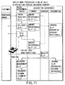
- FIG. 11 shows the slip processing flow in sales work.
- the person in charge in the sales department enters data items, including the commodity code and received order organization code, into an order received slip.
- data is inputted to the delivery slip and claim slip corresponding to the order received slip.
- the slips belonging to the finance department in the accounting division data is inputted to the amount recoverable slip (1) corresponding to the order received slip and the amount recoverable slip (2) corresponding to the scheduled delivery slip.
- data is also inputted to the amount recoverable slip (3) corresponding to the claim slip.
- the commodity code, quantity, unit price, amount of money, and others to be written in the amount recoverable slips (1), (2), and (3) have been transferred automatically when the order received slip, delivery slip, and claim slip have been issued.
- the data is written in the receipt slip in the cashier department.
- collation is made in the recovery management slip. If the receipt is correct, an amount recovered slip is issued.
- the recovery of accounts receivable is added up.
- the accounts receivable are added up on the journal slip when the preceding amount recoverable slip (2) is issued.
- the above slip is subjected to the totalizing process every day as described above.
- the commodity code, the code for the person in charge, the organization code, the customer code, and others correspond to the slip.
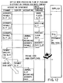
- FIG. 12 shows the slip processing flow in sales work. While FIG. 11 shows an example of receiving an order, FIG. 12 shows an example of placing an order.
- the purchasing department issues an ordering slip.
- An accounts payable slip (1) corresponding to the ordering slip is issued under the control of the finance department.
- the purchasing department issues a receiving slip corresponding to the ordering slip. This slip is such a slip as is issued when the supplier has answered that the commodity is in stock after the order was placed.
- An accounts payable slip (2) corresponding to the receiving slip is issued under the control of the finance department.
- the purchasing department issues a purchase claim slip. Since payment must be made, the purchasing department issues a payment acknowledged slip.
- the finance department issues an accounts payable slip (3) corresponding to the purchase claim slip.
- the finance department issues a payment specifying slip.
- the cashier department issues a payment slip, thereby actually paying money into the bank, paying by draft, or paying in cash.
- the above slip is subjected to the totalizing process every day as described above.
- the commodity code, the code for the person in charge, the organization code, the customer code, and others are included in the header of the slip.
- the information in the slip subjected to the totalizing process includes the date information on that day and days in the future. That is, information on a different day from that day on which the data was processed might be written in the accounts payable slip, payment slip, amount recoverable slip, and receipt slip, and others.
- the slip data items are stored in the data storage locations in the cell allocated to the scheduled days. For example, when the scheduled payment day is today, the slip data is stored in the cell (see FIG. 9) of parameter g0 () on the G-axis. When the scheduled recovery day is tomorrow, the slip data is stored in the cell (see FIG. 9) of parameter g1 () on the G-axis.
- business support involving the above-described totalizing process, merchandise management, and various data management is interlocked through a network in such a manner that it overcomes the time barrier, regional barrier, and language barrier.
- FIG. 13 schematically shows a case where a system of the present invention is constructed, taking domestic areas and overseas areas into account.
- a microcomputer 5001 at the head office at home, a microcomputer 5002 at a branch office in a domestic area, a microcomputer 5003 at a branch office in foreign country 1, and a microcomputer 5004 at a branch office in foreign country 2 are connected to each other via a network 6000 and a communication interface.
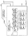
- FIG. 14 shows the basic configuration of the microcomputer.
- Numeral 103 indicates a hardware system control section, where a CPU 111, a ROM 112, and a RAM 113 are connected via a bus 114.
- the operator section 5000 and a disk driver 115 are also connected to the bus 114.
- ROM 112 a program serving as an operating system (OS) that controls the basic operation of the control section 113 is written.
- the CPU 111 exchanges instructions with the ROM 112 and performs operation on the basis of the operating system.
- the RAM 113 is used as work memory for storing data temporarily.
- the bus 114 is connected to a bus 212 via a bus 211. To the bus 212, functional blocks the present invention features are connected. A display 4000 is also connected via a display interface 121 to the bus 212.
- the bus 212 is further connected to a network via a transmission/reception interface 122.
- a network including a public telephone network, the Internet, and an intranet, can be used.
- the image and data appearing on the display 4000 is controlled by a display control section 213.
- the data taken in via a transmission/reception interface 122 is loaded into and stored temporarily in a receiving section 214.
- the data loaded into the receiving section 214 is converted in data format by a data format conversion section 215, if necessary.
- the converted data is stored in the receiving section 214.
- the data stored in a transmitting section 216 is sent via the transmission/reception interface 122 to the network.
- the transmitted data includes the telephone number specifying the called party and the identification number (ID).
- ID the identification number
- the transmitted data is further scrambled and transmitted.
- the data format of the transmitted data might be converted by the data format converting section 215. The reason for this is that the data format of the computer at the called party might differ from the data format of the present system at the calling party.
- the data format converting section 215 has the function of converting item names of the received data, if necessary. This function is needed for the following reasons: for example, when the customer has sent a voucher for the commodity, it is a recovery slip on the reception side; moreover, when the customer has sent a sales claim slip, it corresponds to a purchase claim slip on the reception side; additionally, when the customer has sent an order placed slip, it is an order received slip on the reception side. These conversions belong to the function of converting slip item names.
- the data format converting section 215 further includes a language conversion dictionary for translating business terms in various languages and the function of converting the currency unit.
- the item names in a slip appearing on the screen are prepared in various languages.
- the item names of the corresponding slip can be converted by the language conversion dictionary into the language the user desires.
- the cell control section 3000 as shown in FIG. 4 and a cell file 7000 in which cell groups are stored are connected to the bus 212.
- the sales information as explained in FIGS. 7 and 8 are constructed not only in the cells in the same computer but also in the cells in all the other computers that transmit and receive the data to and from each other.
- the transmitting section 216 functions at the time when the updating process has finished.
- a system setting control section 8000 used to do initial setting in the whole system and correct a function is connected to the bus 212.
- the transmitting section 216 includes a list of transmission destinations and a transmission memory.
- the cell control section 3000 reports that the updating process has been performed (steps A1, A2).
- the transmitting section 216 determines the transmission destination from the list of transmission destinations (step A3) and temporarily copies the X-, Y-, Z-, and G-axis parameters to be transmitted (the parameters specifying each slip explained in FIGS. 7 and 8) and the intelligent data corresponding to the slip into the transmission memory (step A4).
- the transmitting section 216 converts those data items into transmission data (serial) and calls the transmission destination (steps A5, A6).
- the transmission destination is called using the telephone number or password on the basis of the rules of the network.
- the transmitting section transmits the data (steps A7, A8). After the transmission, the transmitting section clears the transmission memory and ends the process (step A9).
- FIG. 16 shows the function of the receiving section 214 when the intelligent data has been received as described above.
- the receiving section 214 sends a reception enable response (steps B1, B2, B3). After sending the response, then the called party sends the data.
- the receiving section 214 loads the data temporarily into the reception memory (step B4).
- the receiving section 214 judges whether the received data is the intelligent data (step B5). If it is the intelligent data, the receiving section 214 replaces the data in the intelligent data cell in the cell file 7000 with the received intelligent data, making use of the received X-, Y-, Z-, and G-axis parameters (the parameters specifying each slip in FIGS. 7 and 8) (step B6). This makes the sales information and stock information resulting from the sale of commodities by persons in charge A, B, C, and D all the same in any computer.
- the receiving process is carried out each time the reception data arrives, and the data is updated.
- the time when transmission is made can be determined arbitrarily according to the transmission rule and is determined at the transmitting section. It is possible to specify the receiving party and prevent the data from an unspecified device from being received. It is also possible to specify the called party and transfer the data only to the specified called party.
- the slip information is transferred to the microcomputer at the head office by the transmission method described earlier. Then, the corresponding data items at the head office are updated. Conversely, when the slip data is updated on the microcomputer at the head office, the slip information is transferred to the microcomputer at a branch office by the transmission method described earlier. Then, the corresponding data items at the branch office are updated. In this way, by sharing the data with plural branch offices, the data would never be lost, even if any one of the microcomputers failed.
- a microcomputer is added to the network and shares the data, it receives the data from another microcomputer by the transmission method described earlier. With this approach, the network system of the present invention realizes a computer with a large-scale, high-speed totalizing function.
- the data format converting section 215, transmitting section 214, receiving section 216, display control section 213, cell control section 3000, and cell file (data storage section) 7000 may be recorded on a recording medium (e.g., an optical disk or a magnetic disk) and the recording medium be installed in a personal computer, thereby realizing the above-described functional blocks.
- a recording medium e.g., an optical disk or a magnetic disk
- the idea of the present invention also covers the data structure recorded on the recording medium and the control data for realizing the above functions.
- the present invention is not restricted to the above embodiment.
- the sales information is transmitted to the section's sales, the department's sales, and the company's sale simultaneously.
- the sales information may be transmitted only to the section level or the smallest group unit level, instead of being transferring to the entire organization at the same time when the commodity was sold. Then, the department's sales information or the company's sales information may be gathered by the executives of the company, if necessary.
- FIG. 17 shows a state where sales information is gathered on a section basis when commodities were sold.
- four persons in charge A, B, C, and D in the same section sold commodities ⁇ and ⁇ and entered data into a sales slip.
- the destinations to which the update flag for each of the persons in charge A, B, C, and D are the section's sales slip 1011, the section's sales slips 1021, 1031 by commodity, and the section's inventory management slips (ledgers) 1041, 1051.
- the amount of money (MT) from each person in charge is recognized as the amount of money (Ms) and the section's sales (MT) are created.
- the slip 1021 is a sales slip for commodity ⁇ and sales information is created section by section automatically.
- the slip 1031 is a sales slip for commodity ⁇ and sales information is created section by section automatically.
- the slip 1041 is an inventory management slip for commodity ⁇ and inventory management information is created section by section automatically.
- the slip 1051 is an inventory management slip for commodity ⁇ and inventory management information is created section by section automatically.
- the transmission/reception decision section 1061 is provided in the receiving section 214, transmitting section 216, or cell control section 3000 in FIG. 4.
- the computer the persons in charge A, B, C, and D operate is the microcomputer 5003 at the branch office in foreign country 1 in FIG. 13.
- the computer 5003 transmits the updated data via the network to the microcomputer 5001 at the head office and the microcomputer 5002 at the branch office.
- the data is stored in the corresponding locations having the identical data structure.
- sales information is constructed in the computer 5001 at the head office in such a manner that it has the same format as that of the data in the computer 5003 in foreign country 1.
- the transmission/reception decision section 1061 is capable of determining not only the data to be transmitted to another computer but also whether to permit the acceptance of the data transmitted from another computer.
- the timing with which the daily totalized data is transmitted to another computer for updating is set in various ways. For example, when computers are provided at a first branch office, for example, one of them is set as the representative computer of the first branch office. The representative computer is so set that the remaining computers used at the first branch office transmit the updated data to the representative computer chronologically. Namely, at the branch offices or the head office, the representative computer gathers the data chronologically.
- time zones for data transmission and reception are determined beforehand.
- the data is transmitted and received on a 6-hour basis, a 12-hour basis, or a 24-hour basis.
- the computer on the data reception side constructs a cell for each day of FIG. 9 using a unique reference (or using local time or the time determined in the world time as a reference).
- the user when the sales for all the branches or the sales for the whole company are required, the user operates the computer. For example, when the user operates the operator section 5000, opens the menu screen, and selects and displays the sales slips for all the branches or for the whole company, the computing processes as shown in FIGS. 7 and 8 are carried out automatically, allowing the user to look at the present sales situation.
- the user when the user gives parameters in the direction of the G-axis to specify the period of inquiry and further specifies an amount recoverable slip, it is possible to totalize the amount of money to be collected written on the amount recoverable slip for several days. This enables the user to know the total sum of money to be collected in a few days. When specifying an accounts receivable slip, the user can know the total sum of money to be paid in a few days.
- FIG. 18 shows examples of the amount recoverable for the whole company and the accounts receivable for the whole company, the present invention is not limited to these.
- the amount recoverable by commodity and the accounts receivable by commodity may be obtained.
- the amount recoverable for each department or division and the account receivable for each department or division may be obtained.
- the system of the present invention enables information (cells) to be transmitted and received freely to and from an affiliated company or another company. This makes it possible to perform a consolidated accounting process in a cooperate group at high speed.
- a recovery slip information (payer information) indicating from which company the money was collected is written.
- a voucher information (payee information) indicating which company the money was paid to is written.
- the amount of money collected for the whole company and the amount of money paid for the whole company can be obtained using those pieces of information as described above.
- Various types of business information about not only the user's company but also other companies can be stored in cells having the data structure of the present invention.
- a balance sheet, a statement of profits and losses, and a cash flow sheet can be created on the microcomputer in each company.
- the daily totalizing file of account titles and a daily totalizing file of subsidiary account titles can be created.
- the file can be created currency by currency since the present system covers international areas.
- pieces of information including consolidated automatic journal slips, consolidation adjustment journal slips, daily totalization of consolidated account titles, and daily totalization of consolidated subsidiary account titles, are transmitted from a subsidiary company to the parent company on the basis of the communication rules. Additionally, consolidated accounting organization information, the beginning balance of consolidated account titles, and the beginning balance of consolidated subsidiary account titles are also transmitted as accounting information to the parent company.
- the parent company can create a consolidated cash flow sheet, a consolidated income statement, a consolidated balance sheet, and the like on the basis of the account information from subsidiary companies.
- the companies which have been registered with each other can carry out a consolidated accounting process easily and automatically. They can execute it monthly, semiannually, or annually.
- the system that has been constructed beforehand is used.
- a computer has to be constructed when it is purchased by the user in such a manner that it has the function the user desires.
- a computer system of the present invention is designed to enable the user to construct such a function.
- the computer system is designed to enable the user to reconstruct the function of the computer so as to adapt to the new company structure.
- FIG. 19 shows the relationship between the control cell 1000, data cell 2000, cell control section 3000, display section 4000, operator section 5000, and display control section 213.
- an address for reading the data in the data cell 2000 is written.
- the address is determined by entering the above-described parameters on each of the X-, Y-, and Z-axes via the cell control section 300 from the operator section 5000.
- the address in the data cell 2000 is specified via the cell control section 3000 and the image data, character data, and numeric data are read. These data items are displayed on the display via the display control section 213.
- the image data includes such frame image data as slips and ledgers.
- the character data includes such data as item names, captions, and names for slips or ledgers.
- the numeric data includes such data as date, sales, and the amount paid. In a microcomputer just purchased, there are such frame data as slips and ledgers. The numeric data items are written as "0", because they will be inputted from now on.
- FIG. 20 shows the process of effecting modeling (D2) after a computer is purchased (D1), setting rules for the use of computers or business rules (D3), and actually using and applying computers (D4) (or the construction and execution processes).
- Modeling means selecting a business function on the computer so as to adapt to the company structure of the user who has purchased the computer.
- Setting rules means setting various rules, including the scope of an employee's official authority (e.g., sales authority or approval authority), the limit of credit given, and various conditions of customers, after the company structure is constructed as an electronic organization on the computer.
- the computer system of the present invention can be adapted easily to the company by just selecting the organization and function after the purchase.
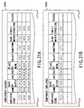
- the personnel structure (Y-axis) of the user's company (X-axis) and the employees' ledger (Z-axis) can be read and displayed. Immediately after the purchase, because the employees' information filling-in field is blank, it is necessary to enter the company's employees' information into the field.
- the input items include code, name, the date of birth, age, post, place of work, salary, hometown, alma mater, family structure, special talent, and comment.
- a temporary employees' ledger is created in a similar manner as shown in FIG. 21B.
- information on additional conditions, including working hours, is added. Some items, including post, hometown, alma mater, and family structure, are omitted.
- a detailed statement of salary for each of the employees and temporary employees must be created.
- the detailed statements of salary are handled at, for example, the cashier's office.
- the user when specifying and displaying the accounting structure (Y-axis) of the company (X-axis) and the detailed statement of salary (Z-axis), the user can deal with the detailed statements of salary for all the employees and temporary employees.
- FIG. 22 shows an example of the detailed statements of salary displayed on the screen.
- the frame of the detailed statement of salary appears and then an employee's code and salary appear.
- the next detailed statement of salary is clicked, then the following different employee's detailed statement of salary comes to the front.
- each employee's detailed statement of salary has been prepared automatically on the basis of each employee's code.
- the amounts of salary have been written in the detailed statements of salary displayed.
- the reason for this is that the address and the transmission destination address have been written in the control data for displaying the employees' ledger.
- the control data is the data stored in the control cell. Although not shown in the field for the amount paid into the bank, it is accompanied by the bank into which salary is to be paid and the number of an employee's bank account.
- FIGS. 21A and 21B the employees' ledger has been explained using an example of the screen appearing on the display in constructing the data. Inside the control cell, however, the transmission destination information on the pieces of information written is attached in such a manner that it is linked with each field of the ledger.
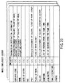
- FIG. 23 shows the data structure format for the whole employees' ledger.
- FIGS. 21A and 21B show the display format for the employees' ledger.
- the detailed statement of salary, place-of-work ledger, and accounting ledger are specified as the transmission destinations of each employee's code and name.
- the transmission destination of post includes the detailed statement of salary and place-of-work ledger.
- the place-of-work information is so specified that it is transferred to the place-of-work ledger.
- the salary information is so specified that it is transferred to the detailed statement of salary and accounting ledger.
- the hometown information is so specified that it is transferred to a list of persons from the same town.
- the alma mater information is so specified that it is transferred to an alumni association ledger.
- FIG. 24 shows a processing routine in a case where data on the detailed statements of salary is constructed automatically after the whole employees' ledger has been created.
- the setup mode is on and the whole employees' ledger has been created (steps E1, E2)
- the number of employees in the salary ledger is counted and as many detailed statements of salary as equal the number of employees are prepared (step E3).
- the detailed statement of salary for each employee is created (E4).
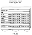
- data on the detailed statement of salary is created in the control cell as shown in FIG. 25.
- data items specifically, the address for the data cell (in the address, data items, including an employee's code and an employee's name, have been written)
- transmission destination information is also incorporated. As for the transmission destination of each data item written in the detailed statement of salary, salary, allowance, premium, and others are transferred to the information part of the corresponding employee's code in the accounting ledger.
- FIG. 26 shows an example of a ledger related to salary at the accounting department.
- the ledger pieces of information on the salary and allowance for each employee are written, followed by transmission destination information for each piece of information. Since the number of the bank account is incidental to the amount paid into the bank, the amount paid into the bank is transmitted to a paying slip for each bank.
- FIG. 27 briefly shows how the salary paid information is transmitted at the accounting division.
- the amount of salary paid to each employee is transmitted to a slip that totals the amount of salary paid in the whole department.
- the total sum of the amount of salary paid in the department is transmitted to a slip that totals the amount of salary paid in the whole company.
- the amount paid into the bank is transmitted to the bank paying slip.
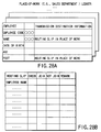
- FIG. 28A shows the state where, for example, the sales department's personnel ledger is created, with the employees' ledger already created.
- the transmission destination information includes a routing slip (FIG. 28B) used in the organization to which the employees belong.
- Information on the name of an employee is transmitted to the field for employee's name on the routing slip.
- the necessary information about the employees is created and then the organization to which each employee belongs is set. After information about the employee's salary is determined, the information is directed automatically to the accounting system.
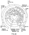
- FIG. 29 shows a standard model when the company is organized.
- various types of slips are circulated. As explained earlier, each of them can be linked with the necessary places.
- FIG. 29 shows each type of functional model set in the system of the present invention. To make it easier to understand, each model is shown, centered on the idea of company management. Each functional model is assigned a reference symbol and will be explained briefly.
- a functional model 500 is a model at the personnel and salary department. When the functional model is turned on, this makes it possible to deal with data items including a detailed statement of salary and a letter of appointment used in doing work related to personnel and salary.
- the individual functional models are classified into the contents of work and the work regulations. Slips handled in the work are allocated to the items about the contents of work. The limits to work and agreement on the work are inputted to the work regulations.
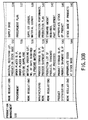
- FIGS. 30A, 30B and 31 The contents of each block in FIG. 29 are shown in detail in FIGS. 30A, 30B and 31.
- the same reference symbols in FIG. 29 are also used in FIGS. 30A, 30B and 31.
- the functional models necessary in business (which may be referred to as functional blocks or functional parts) have been standardized.
- the slips, forms, and others (generally called worksheets) related to the block are displayed. Then, the desired slip and form are selected, the slip and form become active in use now.
- a slip or a form into which no data is entered is recognized as unused on the computer.
- the relevant model is selected. As long as no data is entered into the block, the block is recognized as the block of an used functional model on the computer.
- other related functional models become active, some functional blocks become active automatically. For example, as explained earlier, the worksheets for the functional blocks related to each other, like the personnel ledger and the place-of-work ledger, might become active automatically.
- the user displays the systematized business functional models on the screen, selects the block of the desired functional model, and actually uses the slips and ledgers registered in the functional block, thereby reflecting the user's business on the screen automatically.
- FIG. 32 is a conceptual diagram of what has been explained above.
- a business model (of the freely adaptable type) corresponds to the systematic part of the functional block explained in FIGS. 30A, 30B and 31.
- An application (of the quickly adaptable type) corresponds to the system controlled by entering the data into the slips and ledgers explained in FIGS. 1A to 18.
- the user can display the functional blocks necessary to the company and enter the data into the slips and ledgers in the necessary blocks, thereby constructing a computer system suitable for the company.
- Company A, company B, ... at right in FIG. 32 show the state after they each have constructed their own computer systems.
- the present invention comprises first display means, second display means, third display means, and interlocking control means.
- the first display means has items for functional blocks organized as units in business and displays an item menu for the functional blocks as a result of a call operation.
- the items of jobs done in the organizations of the functional blocks are classified. Names are given to the jobs in such a manner that the job names have meanings in business and suggest their contents.
- the items are defined as worksheets into which working data is entered.
- the second display means has the job items and displays a menu for the job items included in the selected functional block, when any one of the functional blocks displayed on the first display means is selected.
- the third display means displays the worksheet corresponding to the item, when any one of the job items displayed on the second display means.
- the interlocking control means not only superimposes the input data on the worksheet displayed on the third display means, but also supplies the update information to the information transmission destination included in the worksheet.
- FIG. 33 shows the operation at the start-up when initial setting is done in a case where a computer system of the present invention has been purchased as a terminal.
- the business modeling function block is displayed in the form of a menu on the screen (steps F1 and F2). This is done under the control of the system setting control section 8000 of FIG 14.
- the functional block is the outermost functional block shown in FIG. 29, which includes personnel, salary, accounting, financial affairs, production control, sales physical distribution, customer information, marketing, and networking.
- the items for the worksheets (including slips and ledgers) necessary for various jobs done in the functional block are displayed in the form of a menu screen (steps F3 and F4).
- various slips and forms for jobs and rules are displayed.
- the user enters the necessary data into the desired worksheet.
- the desired worksheet For example, the above-described employees' ledger or the like is created.
- information on sales authority e.g., the largest turnover
- is entered for each person in charge (step F5).
- entering the data enables a company structure to be designed automatically on the computer.
- the busy mode is turned on, the system is brought into the in-operation state.
- the user think that the functional blocks are insufficient the user should turn on the setting mode and select and add functional blocks. For example, this is a case where a company that engaged in only sales begins to process parts.
- the present invention is not limited to the above embodiment, which is representative only for the explanation of the basic idea.
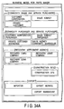
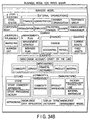
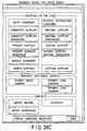
- FIGS. 34A, 34B and 34C show an example of a functional block displayed in the initial setting mode.
- model design panel for any one of company management, factory management, production line, store management, store food processing, and corporate group management can be selected.
- FIGS. 35A and 35B show a state where the company management panel has been selected and opened.
- FIGS. 36A and 36B show a state where the factory management panel has been selected and opened.
- FIG. 37 shows a state where the production line panel has been selected and opened.
- FIGS. 38A and 38B show a state where the store management panel has been selected and opened.
- FIG. 39 shows a state where the store food processing panel has been selected and opened.
- FIG. 40 shows a state where the corporate group management panel has been selected and opened.
- Each panel further has classification items. When any one of the items is selected, the types of worksheets used under the item are displayed.
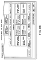
- FIG. 41 shows an example of various types of slips displayed when the item "RECEIVING ORDERS FOR GOODS" is selected under the items of FIGS. 35A and 35B.
- the business items to which the slip belongs become active.
- FIG. 42 shows an example of various types of slips displayed when the item "PLACING ORDERS FOR GOODS" is selected under the items of FIGS. 35A and 35B.
- the business items to which the slip belongs become active.
- FIG. 43 shows an example of various types of slips displayed when the item "GOODS IN STOCK " is selected under the items of FIGS. 35A and 35B.
- the business items to which the slip belongs become active.
- FIG. 44 shows an example of various types of slips displayed when the item "FINANCE" is selected under the items of FIGS. 34A, 34B and 34C.
- the business items to which the slip belongs become active.
- FIG. 45 shows an example of various types of slips displayed when the item "ACCOUNTING" is selected under the items of FIGS. 34A, 34B and 34C.
- the business items to which the slip belongs become active.
- FIG. 46 shows an example of various types of slips displayed when the item "CONSOLIDATED MANAGEMENT" is selected under the items of FIG. 34A, 34B and 34C or 40.
- the business items to which the slip belongs become active.
- control file having the important function of the invention may, of course, be recorded on a recording medium (e.g., an optical disk or a magnetic disk).
- a recording medium e.g., an optical disk or a magnetic disk.
- the recording medium includes:
- the application of the present invention is not limited to the above embodiment. While in the above explanation, the computer body subjected to initial setting or the recording medium includes all the business functional blocks, the information recording medium may be provided for a provider through a network.
- a user who has made a contract may take in the necessary menu information through the network, construct a business model as explained in FIGS. 29 to 40, and load the data in the necessary business block and worksheets into the user's computer.
- the system of the present invention has a communication function and can take in cells. Therefore, by constructing the functional blocks and various worksheets in the direction of the Z-axis of the cell, a unique business model can be obtained and put into operation.
- a business support system As described above, according to the present invention, there are provided a business support system, a business support method, and a business support data recording medium which realize a computer with a large-scale, high-speed totalizing function. Furthermore, according to the present invention, there are provided a business support system, a business support method, and a business support data recording medium which are highly reliable because the data is compensated for by another computer even if any microcomputer terminal has failed. In addition, it is possible to provide a business support system, a business support method, and a business support data recording medium which enable the past data to be stored immediately, even if a new microcomputer is added to the network.
Landscapes
- Engineering & Computer Science (AREA)
- Business, Economics & Management (AREA)
- Human Resources & Organizations (AREA)
- Theoretical Computer Science (AREA)
- Strategic Management (AREA)
- Entrepreneurship & Innovation (AREA)
- General Physics & Mathematics (AREA)
- Physics & Mathematics (AREA)
- Economics (AREA)
- Quality & Reliability (AREA)
- Operations Research (AREA)
- Data Mining & Analysis (AREA)
- Tourism & Hospitality (AREA)
- Marketing (AREA)
- General Business, Economics & Management (AREA)
- Development Economics (AREA)
- Educational Administration (AREA)
- Game Theory and Decision Science (AREA)
- Databases & Information Systems (AREA)
- General Engineering & Computer Science (AREA)
- Management, Administration, Business Operations System, And Electronic Commerce (AREA)
- Computer And Data Communications (AREA)
- Information Transfer Between Computers (AREA)
Applications Claiming Priority (2)
| Application Number | Priority Date | Filing Date | Title |
|---|---|---|---|
| JP19599599A JP2001022730A (ja) | 1999-07-09 | 1999-07-09 | ビジネス支援装置及び記録媒体 |
| JP19599599 | 1999-07-09 |
Publications (2)
| Publication Number | Publication Date |
|---|---|
| EP1074921A2 true EP1074921A2 (fr) | 2001-02-07 |
| EP1074921A3 EP1074921A3 (fr) | 2003-01-22 |
Family
ID=16350482
Family Applications (1)
| Application Number | Title | Priority Date | Filing Date |
|---|---|---|---|
| EP00114026A Withdrawn EP1074921A3 (fr) | 1999-07-09 | 2000-07-04 | Système d'aide aux affaires et support d'enregistrement |
Country Status (7)
| Country | Link |
|---|---|
| EP (1) | EP1074921A3 (fr) |
| JP (1) | JP2001022730A (fr) |
| KR (1) | KR20010039705A (fr) |
| CN (1) | CN1284682A (fr) |
| AU (1) | AU750537C (fr) |
| CA (1) | CA2312875A1 (fr) |
| TW (1) | TW522392B (fr) |
Cited By (2)
| Publication number | Priority date | Publication date | Assignee | Title |
|---|---|---|---|---|
| JP2017168090A (ja) * | 2016-03-14 | 2017-09-21 | 株式会社オービック | プロジェクト別債権管理装置、プロジェクト別債権管理方法、および、プロジェクト別債権管理プログラム |
| JP2017174389A (ja) * | 2016-03-22 | 2017-09-28 | 株式会社オービック | 債権債務管理装置、債権債務管理方法、および、債権債務管理プログラム |
Families Citing this family (8)
| Publication number | Priority date | Publication date | Assignee | Title |
|---|---|---|---|---|
| JP2002342561A (ja) * | 2001-05-14 | 2002-11-29 | Knowledge Soft Corp | ネットワークを利用したビジネスデータ処理装置 |
| US7710853B2 (en) * | 2004-03-18 | 2010-05-04 | Lg Electronics, Inc. | Recording medium with segment information thereon and apparatus and methods for forming, recording, and reproducing the recording medium |
| CN100428761C (zh) * | 2005-08-23 | 2008-10-22 | 中国移动通信集团公司 | 移动终端的软件更新方法 |
| US8392602B2 (en) | 2005-09-30 | 2013-03-05 | Rockwell Automation Technologies, Inc. | Embedding controllers and devices with data to facilitate up-to-date control and configuration information |
| JP2007206894A (ja) * | 2006-01-31 | 2007-08-16 | Chugoku Electric Power Co Inc:The | データ集計システム |
| JP6994907B2 (ja) * | 2017-11-01 | 2022-01-14 | 株式会社オービック | 会社間仕訳連携処理システム、会社間仕訳連携処理方法および会社間仕訳連携処理プログラム |
| KR102351310B1 (ko) * | 2019-03-11 | 2022-01-14 | 장두현 | 다중회사 통합경영관리 프로그램을 기록한 컴퓨터로 판독 가능한 기록매체 |
| TWI831114B (zh) * | 2022-01-14 | 2024-02-01 | 玉山商業銀行股份有限公司 | 跨平台交易與會計分離之完整性驗證方法、系統、電腦裝置及電腦可讀取的記錄媒體 |
Family Cites Families (9)
| Publication number | Priority date | Publication date | Assignee | Title |
|---|---|---|---|---|
| US4989141A (en) * | 1987-06-01 | 1991-01-29 | Corporate Class Software | Computer system for financial analyses and reporting |
| US5008853A (en) * | 1987-12-02 | 1991-04-16 | Xerox Corporation | Representation of collaborative multi-user activities relative to shared structured data objects in a networked workstation environment |
| US5319777A (en) * | 1990-10-16 | 1994-06-07 | Sinper Corporation | System and method for storing and retrieving information from a multidimensional array |
| US5276871A (en) * | 1991-03-18 | 1994-01-04 | Bull Hn Information Systems Inc. | Method of file shadowing among peer systems |
| JPH08314946A (ja) * | 1995-05-12 | 1996-11-29 | Wahei Umesato | 事務処理用データベース設計支援装置 |
| JPH09167191A (ja) * | 1995-12-15 | 1997-06-24 | Casio Comput Co Ltd | データ処理装置 |
| JP3577822B2 (ja) * | 1996-02-14 | 2004-10-20 | 富士ゼロックス株式会社 | 情報提示装置及び情報提示方法 |
| JPH10289172A (ja) * | 1997-04-11 | 1998-10-27 | Nec Corp | データ転送システム |
| JPH11149403A (ja) * | 1997-11-14 | 1999-06-02 | Mitsubishi Electric Corp | データ共有方式およびデータ共有ネットワークシステム |
-
1999
- 1999-07-09 JP JP19599599A patent/JP2001022730A/ja active Pending
-
2000
- 2000-06-29 CA CA002312875A patent/CA2312875A1/fr not_active Abandoned
- 2000-07-04 EP EP00114026A patent/EP1074921A3/fr not_active Withdrawn
- 2000-07-04 AU AU43833/00A patent/AU750537C/en not_active Ceased
- 2000-07-06 KR KR1020000038637A patent/KR20010039705A/ko not_active Ceased
- 2000-07-07 CN CN00119999A patent/CN1284682A/zh active Pending
- 2000-10-05 TW TW089113160A patent/TW522392B/zh active
Cited By (3)
| Publication number | Priority date | Publication date | Assignee | Title |
|---|---|---|---|---|
| JP2017168090A (ja) * | 2016-03-14 | 2017-09-21 | 株式会社オービック | プロジェクト別債権管理装置、プロジェクト別債権管理方法、および、プロジェクト別債権管理プログラム |
| JP2017174389A (ja) * | 2016-03-22 | 2017-09-28 | 株式会社オービック | 債権債務管理装置、債権債務管理方法、および、債権債務管理プログラム |
| JP2021022405A (ja) * | 2016-03-22 | 2021-02-18 | 株式会社オービック | 債権債務管理装置、債権債務管理方法、および、債権債務管理プログラム |
Also Published As
| Publication number | Publication date |
|---|---|
| TW522392B (en) | 2003-03-01 |
| AU750537C (en) | 2003-03-06 |
| CN1284682A (zh) | 2001-02-21 |
| JP2001022730A (ja) | 2001-01-26 |
| EP1074921A3 (fr) | 2003-01-22 |
| AU4383300A (en) | 2001-01-25 |
| AU750537B2 (en) | 2002-07-18 |
| KR20010039705A (ko) | 2001-05-15 |
| CA2312875A1 (fr) | 2001-01-09 |
Similar Documents
| Publication | Publication Date | Title |
|---|---|---|
| US7181427B1 (en) | Automated credit application system | |
| US6058375A (en) | Accounting processor and method for automated management control system | |
| JP4226171B2 (ja) | 取引データを処理する会計システム、およびその方法、並びにそのためのプログラムを格納した記憶媒体 | |
| JP6528070B2 (ja) | 記帳システム | |
| JPWO2001082162A1 (ja) | コンピュータ間通信ネットワークを用いて取引及び決済を管理する方法 | |
| JP2011170490A (ja) | SaaS型汎用会計処理システム | |
| WO2004095207A2 (fr) | Modelisation de donnees d'ordre | |
| CN101071481A (zh) | 一种差旅服务系统和方法 | |
| US11769131B2 (en) | Financial processing and data management system and method | |
| AU750537B2 (en) | A business support system | |
| JP2009176121A (ja) | 経営管理システム | |
| TW559713B (en) | Method and apparatus for managing business data | |
| JP2022134059A (ja) | 電子伝票の統合管理・運用システム | |
| JP2005250809A (ja) | 金融商品取引支援システム | |
| JP3188241B2 (ja) | ネットワーク利用の知的データ処理方法及び装置及び記録媒体 | |
| JP2002158661A (ja) | ネットワーク構築方法と経営レポート収集方法と装置 | |
| KR100719161B1 (ko) | 기업의 근로자 또는 임직원을 위한 복리후생 방법 | |
| JP2003016206A (ja) | 経費運用システム、経費運用方法及び出力媒体 | |
| JP2002117216A (ja) | ビジネス支援装置及び方法及び記録媒体 | |
| JP2002342585A (ja) | 取引明細管理システム | |
| US20230394457A1 (en) | System and Method for Processing Purchase and Financial Data | |
| US20130173328A1 (en) | Computerized system and method for managing injection of resources into a flow of multiple resource utilization events | |
| KR100650225B1 (ko) | 무역서식에 대한 보험가입데이터 추출 시스템 및 방법 | |
| CN113592647A (zh) | 一种基于领域模型抽象的交易方法及系统 | |
| JP2000311198A (ja) | ネットワーク利用の知的データ処理装置 |
Legal Events
| Date | Code | Title | Description |
|---|---|---|---|
| PUAI | Public reference made under article 153(3) epc to a published international application that has entered the european phase |
Free format text: ORIGINAL CODE: 0009012 |
|
| 17P | Request for examination filed |
Effective date: 20000712 |
|
| AK | Designated contracting states |
Kind code of ref document: A2 Designated state(s): AT BE CH CY DE DK ES FI FR GB GR IE IT LI LU MC NL PT SE |
|
| AX | Request for extension of the european patent |
Free format text: AL;LT;LV;MK;RO;SI |
|
| PUAL | Search report despatched |
Free format text: ORIGINAL CODE: 0009013 |
|
| AK | Designated contracting states |
Kind code of ref document: A3 Designated state(s): AT BE CH CY DE DK ES FI FR GB GR IE IT LI LU MC NL PT SE |
|
| AX | Request for extension of the european patent |
Free format text: AL;LT;LV;MK;RO;SI |
|
| RIC1 | Information provided on ipc code assigned before grant |
Free format text: 7G 06F 17/30 A, 7G 06F 17/60 B |
|
| STAA | Information on the status of an ep patent application or granted ep patent |
Free format text: STATUS: THE APPLICATION HAS BEEN WITHDRAWN |
|
| 18W | Application withdrawn |
Effective date: 20030416 |