EP1075109A2 - Kabelmodem mit einer drahtlosen Kommunikationsfunktion - Google Patents
Kabelmodem mit einer drahtlosen Kommunikationsfunktion Download PDFInfo
- Publication number
- EP1075109A2 EP1075109A2 EP00306577A EP00306577A EP1075109A2 EP 1075109 A2 EP1075109 A2 EP 1075109A2 EP 00306577 A EP00306577 A EP 00306577A EP 00306577 A EP00306577 A EP 00306577A EP 1075109 A2 EP1075109 A2 EP 1075109A2
- Authority
- EP
- European Patent Office
- Prior art keywords
- cable modem
- expansion unit
- information
- cable
- information processing
- Prior art date
- Legal status (The legal status is an assumption and is not a legal conclusion. Google has not performed a legal analysis and makes no representation as to the accuracy of the status listed.)
- Ceased
Links
- 238000004891 communication Methods 0.000 title claims abstract description 43
- 230000010365 information processing Effects 0.000 claims abstract description 36
- 238000012546 transfer Methods 0.000 claims abstract description 23
- 230000008878 coupling Effects 0.000 claims description 8
- 238000010168 coupling process Methods 0.000 claims description 8
- 238000005859 coupling reaction Methods 0.000 claims description 8
- 238000005259 measurement Methods 0.000 claims description 6
- 238000000034 method Methods 0.000 description 10
- 238000010586 diagram Methods 0.000 description 9
- 238000010276 construction Methods 0.000 description 5
- 238000006243 chemical reaction Methods 0.000 description 4
- 230000005540 biological transmission Effects 0.000 description 3
- 238000009434 installation Methods 0.000 description 2
- 230000003247 decreasing effect Effects 0.000 description 1
Images


Classifications
-
- H—ELECTRICITY
- H04—ELECTRIC COMMUNICATION TECHNIQUE
- H04N—PICTORIAL COMMUNICATION, e.g. TELEVISION
- H04N7/00—Television systems
- H04N7/10—Adaptations for transmission by electrical cable
-
- H—ELECTRICITY
- H04—ELECTRIC COMMUNICATION TECHNIQUE
- H04L—TRANSMISSION OF DIGITAL INFORMATION, e.g. TELEGRAPHIC COMMUNICATION
- H04L12/00—Data switching networks
- H04L12/28—Data switching networks characterised by path configuration, e.g. LAN [Local Area Networks] or WAN [Wide Area Networks]
- H04L12/46—Interconnection of networks
- H04L12/4604—LAN interconnection over a backbone network, e.g. Internet, Frame Relay
- H04L12/462—LAN interconnection over a bridge based backbone
- H04L12/4625—Single bridge functionality, e.g. connection of two networks over a single bridge
-
- H—ELECTRICITY
- H04—ELECTRIC COMMUNICATION TECHNIQUE
- H04L—TRANSMISSION OF DIGITAL INFORMATION, e.g. TELEGRAPHIC COMMUNICATION
- H04L1/00—Arrangements for detecting or preventing errors in the information received
- H04L1/0001—Systems modifying transmission characteristics according to link quality, e.g. power backoff
- H04L1/0002—Systems modifying transmission characteristics according to link quality, e.g. power backoff by adapting the transmission rate
-
- H—ELECTRICITY
- H04—ELECTRIC COMMUNICATION TECHNIQUE
- H04L—TRANSMISSION OF DIGITAL INFORMATION, e.g. TELEGRAPHIC COMMUNICATION
- H04L12/00—Data switching networks
- H04L12/28—Data switching networks characterised by path configuration, e.g. LAN [Local Area Networks] or WAN [Wide Area Networks]
- H04L12/2801—Broadband local area networks
-
- H—ELECTRICITY
- H04—ELECTRIC COMMUNICATION TECHNIQUE
- H04W—WIRELESS COMMUNICATION NETWORKS
- H04W84/00—Network topologies
- H04W84/02—Hierarchically pre-organised networks, e.g. paging networks, cellular networks, WLAN [Wireless Local Area Network] or WLL [Wireless Local Loop]
- H04W84/10—Small scale networks; Flat hierarchical networks
- H04W84/12—WLAN [Wireless Local Area Networks]
-
- H—ELECTRICITY
- H04—ELECTRIC COMMUNICATION TECHNIQUE
- H04W—WIRELESS COMMUNICATION NETWORKS
- H04W88/00—Devices specially adapted for wireless communication networks, e.g. terminals, base stations or access point devices
- H04W88/08—Access point devices
Definitions
- the present invention relates to a cable modem that exchanges information by using a CATV network as an information transfer medium.
- FIG. 9 An example of a conventional cable modem is shown in Fig. 9.
- This cable modem 81 is, on the one hand, connected by way of a 75 ⁇ coaxial cable 82 to a CATV station (head end) of a CATV network (not shown), and, on the other hand, connected by way of cables 84a, 84b, ... , such as a LAN cable and a USB (universal serial bus) cable, to an information processing terminals 83a, 83b, ... , such as personal computers (this system will be referred to as conventional system 1).
- reference numeral 91 represents a set-top box connected to an RF coaxial cable 100
- reference numeral 92 represents a television monitor connected to the set-top box.
- Reference symbol LO represents a living room
- reference symbols L1 and L2 represent other rooms separate therefrom.
- Japanese Patent Application Laid-Open No. H10-234028 discloses a cable modem (CATV home unit) provided with a CATV data transmission/reception unit and a wireless LAN unit.
- CATV data transmission/reception unit is connected by way of a CATV cable to a CATV network, and is connected to individual information processing terminals through wireless communication by the wireless LAN unit (this system will be referred to as conventional system 2).
- the connection between the cable modem 81 and information processing terminals 83a, 83b, ... , such as personal computers, requires installation of cables 84a, 84b, ... , such as a LAN cable and a USB cable.
- cables 84a, 84b, ... such as a LAN cable and a USB cable.
- installation of the cables requires large-scale work.
- An object of the present invention is to provide a cable modem having a wireless communication function that permits easy and inexpensive switching from wired communication to wireless communication.
- a cable modem having a wireless communication function and using a CATV network as an information transfer medium is provided with a cable modem proper that is connected by way of a coaxial cable to a CATV network and an expansion unit attached thereto having a wireless LAN function that permits communication with an information processing terminal on a wireless basis.
- this expansion unit and the cable modem proper are coupled together by use of a plug and a connector in such a way as to be freely removable. This permits easy switching from wired communication to wireless communication.
- the plug in this cable modem configured as described above, is a plug for a LAN cable and the connector is a connector for a LAN cable. This permits easy switching from wired communication to wireless communication.
- the bit error rate of the expansion unit is measured at regular time intervals so that the output level and the data transfer rate are varied according to the measurement results in order to keep communication quality above a predetermined level.
- a wireless network is used for communication with an information processing terminal, there is the risk of poor communication quality depending on the location of the information processing terminal. Even in such a case, this configuration makes it possible to keep communication quality above a predetermined level all the time.
- the cable modem has a function of transmitting information on how much to increase or decrease the output level according to the measurement results to an interface portion of the information processing terminal that communicates with the cable modem on a wireless basis.
- This permits the output level and the data transfer rate to be adjusted also in the interface portion of the information processing terminal, and thereby makes it possible to keep communication quality above a predetermined level all the time also on the part of the information processing terminal. That is, by adjusting the output level and the data transfer rate in both the cable modem and the interface portion of the information processing terminal, it is possible to keep communication quality above a predetermined level.
- Fig. 1 is a block diagram showing the system configuration of a cable modem having a wireless communication function according to the invention.
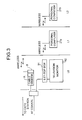
- Fig. 2 is a block diagram showing the configuration of the interface portion attached to an information processing terminal.
- the cable modem is composed of a cable modem proper A and an expansion unit B.
- the cable modem proper A includes a tuner 1, a CATV-side modulator/demodulator 2 (a DEMOD (demodulator) 2a and a MOD (modulator) 2b), a first MAC (medium access controller) 3, a CPU 4, a buffer 5, and a second MAC.
- the expansion unit B includes an SS wireless part 7 that performs modulation/demodulation and frequency conversion on the wireless side, an output level adjuster 8, and an antenna 9.
- the interface portion C attached to the information processing terminal 27 includes an output level adjuster 21, a reception amplifier (power amplifier) 22, a frequency converter 23, a modulator/demodulator 24, a MAC 25, and an output controller 26.
- the tuner 1 selects information received from a CATV network, converts it into a demodulatable intermediate frequency, and feeds it to the demodulator 2a.
- the tuner 1 also incorporates a filter through which it transmits a modulated signal to the CATV network. Thus, through this filter, the tuner 1 sends out information fed from the modulator 2b to the CATV network, and takes in information from the CATV network into the cable modem.
- the DEMOD (demodulator) 2a demodulates the intermediate-frequency output, generally QAM-modulated, fed from the tuner 1 and converts it into data packets, which are then fed to the first MAC 3.
- the MOD (modulator) 2b modulates the output of the first MAC 3 (i.e. information to be transmitted to the CATV network), generally into a QPSK signal format, and feeds it to the tuner 1.
- the first MAC 3 classifies, or categorizes, information from the CATV network and information from a subscriber (end user) into signals to be processed inside the cable modem and signals to be transmitted to the subscriber or to the CATV network.
- the first MAC 3 also adds and removes headers and footers to and from data packets, i.e. packets of information, so as to convert the format of data packets.
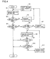
- the CPU 4 controls the direction and timing in and with which to output information, and stores the information to be output temporarily in the buffer 5. Moreover, actually using the wireless-side network, the CPU 4 measures the BER (bit error rate) and, according to the thus measured BER, feeds the output level adjuster 8 of the expansion unit B with a signal that instructs it to increase or decrease the output level on the wireless side. This signal, requesting an increase or decrease in the output level, is also transmitted through the wireless circuit of the expansion unit B to the interface portion C (see Fig. 2) of a subscriber. On the basis of this signal, the interface portion C of the subscriber adjusts, through the output controller 26, the output level of the output level adjuster 21.
- BER bit error rate
- step S1 the BER on the wireless network side is measured (step S1), and whether the measured BER value is equal to or greater than a first predetermined threshold value or not is checked (step S2). If the BER value is smaller than the first threshold value (i.e. if the check in step S2 results in "no"), a signal requesting a decrease in the output level is fed to the output level adjuster 8 of the expansion unit B to decrease the output level (step S3), and the data transfer rate is set at the maximum value (step S4).
- the BER value is equal to or greater than the first threshold value (i.e. if the check in step S2 results in "yes")
- the second threshold value > the first threshold value is checked (step S5). If the BER value is smaller than the second threshold value (i.e. if the check in step S5 results in "yes"), the current output level is judged to be adequate, and the procedure is ended without outputting a signal.
- step S6 whether the output level of the output level adjuster 8 has already reached the upper limit or not is checked. If the output level has not reached the upper limit (i.e. if the check in step S6 results in "no"), a signal requesting an increase in the output level is fed to the output level adjuster 8 of the expansion unit B to increase the output level (step S7), and the data transfer rate is set at the maximum value (step S4).
- step 6 the output level is found to have reached the upper limit (i.e. if the check in step S6 results in "yes")
- step 8 the BER on the wireless network side is measured again
- step S9 the output level is judged to be adequate, and the procedure is ended without outputting a signal.
- step S10 whether the data transfer rate at that time is at the minimum value or not is checked. If the data transfer rate is at the minimum value, the procedure is ended. On the other hand, if the data transfer rate is not at the minimum value (i.e. if the check in step S10 results in "no"), the data transfer rate is further decreased (step S11), and then the procedure returns to step S8. Thereafter, the operations in steps S8 to S11 are repeated.
- CPE customer premises equipment
- MCNS standards
- the output level and the data transfer rate are adjusted in the manner described above.
- the second MAC 6 converts and classifies data on the wireless side, and also exchanges data between the cable modem proper and the SS wireless part 7.
- IP-conforming data packets are used, and therefore, with respect to data security, it is possible to use conventional security techniques, such as those using a public or secret key, as they are.
- the SS wireless part 7 performs modulation for transmission and demodulation for reception on the wireless side. With respect to this SS wireless part 7, it is possible to readily utilize the modulation/demodulation techniques used in conventional wireless modems.
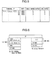
- Fig. 6 is a protocol stack diagram showing the data conversion processes in the first and second MACs 3 and 6.
- Fig. 3 shows an example of the construction of a network system employing a cable modem according to the present invention. The features of this construction will be clear if compared with the conventional example shown in Fig. 9.
- reference numeral 91 represents a set-top box
- reference numeral 92 represents a television monitor
- 27a and 27b represent personal computers.
- the information that the cable modem has received from the CATV network is first demodulated, and then the first MAC 3 separates the information into control information required by the cable modem itself and information to be transmitted to a subscriber's information processing terminal.
- the first MAC 3 separates the information into control information required by the cable modem itself and information to be transmitted to a subscriber's information processing terminal.
- the thus separated information is subjected to modulation and then to frequency conversion, and is then transmitted to the information processing terminal.
- the information that the cable modem has received from the information processing terminal through the interface portion C is demodulated, and is then, after identifying the sender by referring to the management table shown in Fig. 5, separated into messages to the cable modem itself and information to be transmitted to the CATV station (head end). This information is then modulated and send out to the CATV network.
- Figs. 7 and 8 are external perspective views showing examples of the coupling mechanism between the cable modem proper A and the expansion unit B of the cable modem having a wireless communication function configured as described above.
- a plug 13 is provided in the cable modem proper A, and a connector 12 is provided in the portion facing it of the expansion unit B, constituting as a whole a coupling mechanism of a slot-in type.
- a connector for example, an RJ-45 jack
- a plug for example, an RJ-45 plug
- This coupling mechanism which couples the cable modem proper A and the expansion unit B together by use of LAN connectors, permits easy switching between wired and wireless communication.
- a cable modem having a wireless communication function is provided with a cable modem proper that is connected by way of a coaxial cable to a CATV network and an expansion unit attached thereto having a wireless LAN function that permits communication with an information processing terminal on a wireless basis.
- this expansion unit and the cable modem proper are coupled together by use of a plug and a connector in such a way as to be freely removable. This permits easy switching from wired communication to wireless communication.
- the bit error rate of the expansion unit is measured at regular time intervals so that the output level and the data transfer rate are varied according to the measurement results in order to keep communication quality above a predetermined level.
- a wireless network is used for communication with an information processing terminal, there is the risk of poor communication quality depending on the location of the information processing terminal. Even in such a case, this configuration makes it possible to keep communication quality above a predetermined level all the time.
- the cable modem has a function of transmitting information on how much to increase or decrease the output level according to the measurement results to an interface portion of the information processing terminal that communicates with the cable modem on a wireless basis.
- This permits the output level and the data transfer rate to be adjusted also in the interface portion of the information processing terminal, and thereby makes it possible to keep communication quality above a predetermined level all the time also on the part of the information processing terminal. That is, by adjusting the output level and the data transfer rate in both the cable modem and the interface portion of the information processing terminal, it is possible to keep communication quality above a predetermined level. Moreover, by adjusting the output level adequately, it is possible to save energy.
Landscapes
- Engineering & Computer Science (AREA)
- Signal Processing (AREA)
- Computer Networks & Wireless Communication (AREA)
- Quality & Reliability (AREA)
- Multimedia (AREA)
- Small-Scale Networks (AREA)
- Two-Way Televisions, Distribution Of Moving Picture Or The Like (AREA)
- Communication Control (AREA)
- Mobile Radio Communication Systems (AREA)
- Telephonic Communication Services (AREA)
- Computer And Data Communications (AREA)
Applications Claiming Priority (2)
| Application Number | Priority Date | Filing Date | Title |
|---|---|---|---|
| JP22257699 | 1999-08-05 | ||
| JP22257699A JP3392077B2 (ja) | 1999-08-05 | 1999-08-05 | 無線通信機能付きケーブルモデム |
Publications (2)
| Publication Number | Publication Date |
|---|---|
| EP1075109A2 true EP1075109A2 (de) | 2001-02-07 |
| EP1075109A3 EP1075109A3 (de) | 2003-03-19 |
Family
ID=16784643
Family Applications (1)
| Application Number | Title | Priority Date | Filing Date |
|---|---|---|---|
| EP00306577A Ceased EP1075109A3 (de) | 1999-08-05 | 2000-08-02 | Kabelmodem mit einer drahtlosen Kommunikationsfunktion |
Country Status (5)
| Country | Link |
|---|---|
| US (1) | US6931659B1 (de) |
| EP (1) | EP1075109A3 (de) |
| JP (1) | JP3392077B2 (de) |
| KR (1) | KR100340919B1 (de) |
| CN (1) | CN1168230C (de) |
Cited By (6)
| Publication number | Priority date | Publication date | Assignee | Title |
|---|---|---|---|---|
| EP1414241A1 (de) * | 2002-10-23 | 2004-04-28 | Fondazione Ugo Bordoni | System zur transparenten Übertragung von Radiofrequenzsignalen auf einem Kabelnetz |
| EP1237317A3 (de) * | 2001-02-28 | 2007-04-04 | Nec Corporation | Verfahren und System zum Wechsel von Übertragungsmodus |
| FR2913159A1 (fr) * | 2007-06-29 | 2008-08-29 | Thomson Licensing Sas | Methode et interface de connexion d'un reseau sans fil et d'un resaeu coaxial |
| US9253003B1 (en) | 2014-09-25 | 2016-02-02 | Corning Optical Communications Wireless Ltd | Frequency shifting a communications signal(S) in a multi-frequency distributed antenna system (DAS) to avoid or reduce frequency interference |
| US9338823B2 (en) | 2012-03-23 | 2016-05-10 | Corning Optical Communications Wireless Ltd | Radio-frequency integrated circuit (RFIC) chip(s) for providing distributed antenna system functionalities, and related components, systems, and methods |
| US9813229B2 (en) | 2007-10-22 | 2017-11-07 | Corning Optical Communications Wireless Ltd | Communication system using low bandwidth wires |
Families Citing this family (88)
| Publication number | Priority date | Publication date | Assignee | Title |
|---|---|---|---|---|
| US6842459B1 (en) | 2000-04-19 | 2005-01-11 | Serconet Ltd. | Network combining wired and non-wired segments |
| US7346918B2 (en) | 2000-12-27 | 2008-03-18 | Z-Band, Inc. | Intelligent device system and method for distribution of digital signals on a wideband signal distribution system |
| US8601519B1 (en) * | 2000-12-28 | 2013-12-03 | At&T Intellectual Property I, L.P. | Digital residential entertainment system |
| US7698723B2 (en) * | 2000-12-28 | 2010-04-13 | At&T Intellectual Property I, L.P. | System and method for multimedia on demand services |
| US8677423B2 (en) * | 2000-12-28 | 2014-03-18 | At&T Intellectual Property I, L. P. | Digital residential entertainment system |
| US20020157115A1 (en) * | 2001-04-24 | 2002-10-24 | Koninklijke Philips Electronics N.V. | Wireless communication point of deployment module for use in digital cable compliant devices |
| IL161190A0 (en) | 2001-10-11 | 2004-08-31 | Serconet Ltd | Outlet with analog signal adapter, method for use thereof and a network using said outlet |
| US20030115610A1 (en) * | 2001-12-14 | 2003-06-19 | Insik Cho | Cable modem (or xDSL modem) integrated with access point |
| KR100511291B1 (ko) * | 2002-03-22 | 2005-08-31 | 엘지전자 주식회사 | 무선통신에서의 영상신호 전송방법 |
| KR100474434B1 (ko) * | 2002-07-19 | 2005-03-10 | 삼성전자주식회사 | 디지털 영상시스템 및 그 제어방법 |
| IL152824A (en) | 2002-11-13 | 2012-05-31 | Mosaid Technologies Inc | A socket that can be connected to and the network that uses it |
| JP2004214722A (ja) * | 2002-12-26 | 2004-07-29 | Sharp Corp | ケーブルモデム用チューナおよびこれを備えたケーブルモデム |
| JP2004253900A (ja) * | 2003-02-18 | 2004-09-09 | Renesas Technology Corp | 通信補助装置および通信補助装置を用いた通信システム |
| US7162234B1 (en) | 2003-05-20 | 2007-01-09 | Mark J. Smith | Wireless communication device |
| US7023871B2 (en) * | 2003-05-28 | 2006-04-04 | Terayon Communication Systems, Inc. | Wideband DOCSIS on catv systems using port-trunking |
| US7668098B2 (en) * | 2003-06-19 | 2010-02-23 | Intel Corporation | Method and apparatus for improving the upstream data transfer rate for a cable modem |
| IL157787A (en) | 2003-09-07 | 2010-12-30 | Mosaid Technologies Inc | Modular outlet for data communications network |
| CN100385878C (zh) * | 2003-11-11 | 2008-04-30 | 华为技术有限公司 | 宽带网络中的终端接入设备及其接入网络的方法 |
| IL159838A0 (en) | 2004-01-13 | 2004-06-20 | Yehuda Binder | Information device |
| IL160417A (en) | 2004-02-16 | 2011-04-28 | Mosaid Technologies Inc | Unit added to the outlet |
| CN100389574C (zh) * | 2004-03-19 | 2008-05-21 | 联想(北京)有限公司 | 一种近距无线通信的移动终端及其实现方法 |
| IL161869A (en) * | 2004-05-06 | 2014-05-28 | Serconet Ltd | A system and method for carrying a signal originating is wired using wires |
| US7873058B2 (en) | 2004-11-08 | 2011-01-18 | Mosaid Technologies Incorporated | Outlet with analog signal adapter, a method for use thereof and a network using said outlet |
| US8059539B2 (en) * | 2004-12-29 | 2011-11-15 | Hewlett-Packard Development Company, L.P. | Link throughput enhancer |
| GB0500601D0 (en) * | 2005-01-13 | 2005-02-16 | Koninkl Philips Electronics Nv | Communication device and method of communication using wireless communication protocol |
| US7813451B2 (en) | 2006-01-11 | 2010-10-12 | Mobileaccess Networks Ltd. | Apparatus and method for frequency shifting of a wireless signal and systems using frequency shifting |
| US8873585B2 (en) | 2006-12-19 | 2014-10-28 | Corning Optical Communications Wireless Ltd | Distributed antenna system for MIMO technologies |
| US20100054746A1 (en) | 2007-07-24 | 2010-03-04 | Eric Raymond Logan | Multi-port accumulator for radio-over-fiber (RoF) wireless picocellular systems |
| US8175459B2 (en) | 2007-10-12 | 2012-05-08 | Corning Cable Systems Llc | Hybrid wireless/wired RoF transponder and hybrid RoF communication system using same |
| US8175649B2 (en) | 2008-06-20 | 2012-05-08 | Corning Mobileaccess Ltd | Method and system for real time control of an active antenna over a distributed antenna system |
| WO2009081376A2 (en) | 2007-12-20 | 2009-07-02 | Mobileaccess Networks Ltd. | Extending outdoor location based services and applications into enclosed areas |
| US8887220B2 (en) * | 2008-07-25 | 2014-11-11 | At&T Intellectual Property I, L.P. | Network interface devices |
| EP2394379B1 (de) | 2009-02-03 | 2016-12-28 | Corning Optical Communications LLC | Verteilte antennensysteme auf glasfaserbasis, bestandteile und entsprechende verfahren zu ihrer kalibrierung |
| AU2010210766A1 (en) | 2009-02-03 | 2011-09-15 | Corning Cable Systems Llc | Optical fiber-based distributed antenna systems, components, and related methods for monitoring and configuring thereof |
| US9673904B2 (en) | 2009-02-03 | 2017-06-06 | Corning Optical Communications LLC | Optical fiber-based distributed antenna systems, components, and related methods for calibration thereof |
| WO2010089719A1 (en) | 2009-02-08 | 2010-08-12 | Mobileaccess Networks Ltd. | Communication system using cables carrying ethernet signals |
| US9590733B2 (en) | 2009-07-24 | 2017-03-07 | Corning Optical Communications LLC | Location tracking using fiber optic array cables and related systems and methods |
| US8279805B2 (en) | 2009-08-24 | 2012-10-02 | At&T Intellectual Property I, L.P. | Residential gateway |
| US8280259B2 (en) | 2009-11-13 | 2012-10-02 | Corning Cable Systems Llc | Radio-over-fiber (RoF) system for protocol-independent wired and/or wireless communication |
| US20110176496A1 (en) * | 2010-01-15 | 2011-07-21 | Roy Rabinda K | On-the-fly video quality switching for video distribution networks and methods therefor |
| US8275265B2 (en) | 2010-02-15 | 2012-09-25 | Corning Cable Systems Llc | Dynamic cell bonding (DCB) for radio-over-fiber (RoF)-based networks and communication systems and related methods |
| WO2011123336A1 (en) | 2010-03-31 | 2011-10-06 | Corning Cable Systems Llc | Localization services in optical fiber-based distributed communications components and systems, and related methods |
| US8570914B2 (en) | 2010-08-09 | 2013-10-29 | Corning Cable Systems Llc | Apparatuses, systems, and methods for determining location of a mobile device(s) in a distributed antenna system(s) |
| US9160449B2 (en) | 2010-10-13 | 2015-10-13 | Ccs Technology, Inc. | Local power management for remote antenna units in distributed antenna systems |
| US9252874B2 (en) | 2010-10-13 | 2016-02-02 | Ccs Technology, Inc | Power management for remote antenna units in distributed antenna systems |
| EP2643947B1 (de) | 2010-11-24 | 2018-09-19 | Corning Optical Communications LLC | Stromverteilungsmodul(e) mit heissstart- und/oder stoppfunktion für verteilte antennensysteme und zugehörige aggregate, komponenten, und verfahren |
| US11296504B2 (en) | 2010-11-24 | 2022-04-05 | Corning Optical Communications LLC | Power distribution module(s) capable of hot connection and/or disconnection for wireless communication systems, and related power units, components, and methods |
| WO2012148940A1 (en) | 2011-04-29 | 2012-11-01 | Corning Cable Systems Llc | Systems, methods, and devices for increasing radio frequency (rf) power in distributed antenna systems |
| CN103548290B (zh) | 2011-04-29 | 2016-08-31 | 康宁光缆系统有限责任公司 | 判定分布式天线系统中的通信传播延迟及相关组件、系统与方法 |
| KR101799311B1 (ko) * | 2011-06-28 | 2017-11-21 | 삼성전자 주식회사 | 무선통신장치 및 그 제어방법 |
| USD704175S1 (en) * | 2012-03-02 | 2014-05-06 | Interlite Ab | Wireless communication interface |
| WO2013148986A1 (en) | 2012-03-30 | 2013-10-03 | Corning Cable Systems Llc | Reducing location-dependent interference in distributed antenna systems operating in multiple-input, multiple-output (mimo) configuration, and related components, systems, and methods |
| CN102664794A (zh) * | 2012-04-18 | 2012-09-12 | 苏州泽佑科技有限公司 | 可相互连接的路由器 |
| US9781553B2 (en) | 2012-04-24 | 2017-10-03 | Corning Optical Communications LLC | Location based services in a distributed communication system, and related components and methods |
| EP2842245A1 (de) | 2012-04-25 | 2015-03-04 | Corning Optical Communications LLC | Verteilte antennensystemarchitekturen |
| US9154222B2 (en) | 2012-07-31 | 2015-10-06 | Corning Optical Communications LLC | Cooling system control in distributed antenna systems |
| WO2014024192A1 (en) | 2012-08-07 | 2014-02-13 | Corning Mobile Access Ltd. | Distribution of time-division multiplexed (tdm) management services in a distributed antenna system, and related components, systems, and methods |
| US9455784B2 (en) | 2012-10-31 | 2016-09-27 | Corning Optical Communications Wireless Ltd | Deployable wireless infrastructures and methods of deploying wireless infrastructures |
| US10257056B2 (en) | 2012-11-28 | 2019-04-09 | Corning Optical Communications LLC | Power management for distributed communication systems, and related components, systems, and methods |
| CN105308876B (zh) | 2012-11-29 | 2018-06-22 | 康宁光电通信有限责任公司 | 分布式天线系统中的远程单元天线结合 |
| US9647758B2 (en) | 2012-11-30 | 2017-05-09 | Corning Optical Communications Wireless Ltd | Cabling connectivity monitoring and verification |
| US9158864B2 (en) | 2012-12-21 | 2015-10-13 | Corning Optical Communications Wireless Ltd | Systems, methods, and devices for documenting a location of installed equipment |
| US9497706B2 (en) | 2013-02-20 | 2016-11-15 | Corning Optical Communications Wireless Ltd | Power management in distributed antenna systems (DASs), and related components, systems, and methods |
| EP3008828B1 (de) | 2013-06-12 | 2017-08-09 | Corning Optical Communications Wireless Ltd. | Zeitduplexierung (tdd) in verteilten kommunikationssystemen, einschliesslich verteilten antennensystemen (dass) |
| WO2014199384A1 (en) | 2013-06-12 | 2014-12-18 | Corning Optical Communications Wireless, Ltd. | Voltage controlled optical directional coupler |
| US9247543B2 (en) | 2013-07-23 | 2016-01-26 | Corning Optical Communications Wireless Ltd | Monitoring non-supported wireless spectrum within coverage areas of distributed antenna systems (DASs) |
| US9661781B2 (en) | 2013-07-31 | 2017-05-23 | Corning Optical Communications Wireless Ltd | Remote units for distributed communication systems and related installation methods and apparatuses |
| EP3039814B1 (de) | 2013-08-28 | 2018-02-21 | Corning Optical Communications Wireless Ltd. | Leistungssteuerung für verteilte kommunikationssysteme sowie entsprechende komponenten, systeme und verfahren |
| US9385810B2 (en) | 2013-09-30 | 2016-07-05 | Corning Optical Communications Wireless Ltd | Connection mapping in distributed communication systems |
| WO2015079435A1 (en) | 2013-11-26 | 2015-06-04 | Corning Optical Communications Wireless Ltd. | Selective activation of communications services on power-up of a remote unit(s) in a distributed antenna system (das) based on power consumption |
| US9178635B2 (en) | 2014-01-03 | 2015-11-03 | Corning Optical Communications Wireless Ltd | Separation of communication signal sub-bands in distributed antenna systems (DASs) to reduce interference |
| US9775123B2 (en) | 2014-03-28 | 2017-09-26 | Corning Optical Communications Wireless Ltd. | Individualized gain control of uplink paths in remote units in a distributed antenna system (DAS) based on individual remote unit contribution to combined uplink power |
| US9357551B2 (en) | 2014-05-30 | 2016-05-31 | Corning Optical Communications Wireless Ltd | Systems and methods for simultaneous sampling of serial digital data streams from multiple analog-to-digital converters (ADCS), including in distributed antenna systems |
| US9509133B2 (en) | 2014-06-27 | 2016-11-29 | Corning Optical Communications Wireless Ltd | Protection of distributed antenna systems |
| US9525472B2 (en) | 2014-07-30 | 2016-12-20 | Corning Incorporated | Reducing location-dependent destructive interference in distributed antenna systems (DASS) operating in multiple-input, multiple-output (MIMO) configuration, and related components, systems, and methods |
| US9730228B2 (en) | 2014-08-29 | 2017-08-08 | Corning Optical Communications Wireless Ltd | Individualized gain control of remote uplink band paths in a remote unit in a distributed antenna system (DAS), based on combined uplink power level in the remote unit |
| TWI538431B (zh) * | 2014-09-02 | 2016-06-11 | 宏正自動科技股份有限公司 | 地面數位視訊廣播系統及其調變方法 |
| US9653861B2 (en) | 2014-09-17 | 2017-05-16 | Corning Optical Communications Wireless Ltd | Interconnection of hardware components |
| US9602210B2 (en) | 2014-09-24 | 2017-03-21 | Corning Optical Communications Wireless Ltd | Flexible head-end chassis supporting automatic identification and interconnection of radio interface modules and optical interface modules in an optical fiber-based distributed antenna system (DAS) |
| US9420542B2 (en) | 2014-09-25 | 2016-08-16 | Corning Optical Communications Wireless Ltd | System-wide uplink band gain control in a distributed antenna system (DAS), based on per band gain control of remote uplink paths in remote units |
| US9729267B2 (en) | 2014-12-11 | 2017-08-08 | Corning Optical Communications Wireless Ltd | Multiplexing two separate optical links with the same wavelength using asymmetric combining and splitting |
| US20160249365A1 (en) | 2015-02-19 | 2016-08-25 | Corning Optical Communications Wireless Ltd. | Offsetting unwanted downlink interference signals in an uplink path in a distributed antenna system (das) |
| US9785175B2 (en) | 2015-03-27 | 2017-10-10 | Corning Optical Communications Wireless, Ltd. | Combining power from electrically isolated power paths for powering remote units in a distributed antenna system(s) (DASs) |
| US9681313B2 (en) | 2015-04-15 | 2017-06-13 | Corning Optical Communications Wireless Ltd | Optimizing remote antenna unit performance using an alternative data channel |
| US9948349B2 (en) | 2015-07-17 | 2018-04-17 | Corning Optical Communications Wireless Ltd | IOT automation and data collection system |
| US10560214B2 (en) | 2015-09-28 | 2020-02-11 | Corning Optical Communications LLC | Downlink and uplink communication path switching in a time-division duplex (TDD) distributed antenna system (DAS) |
| US9648580B1 (en) | 2016-03-23 | 2017-05-09 | Corning Optical Communications Wireless Ltd | Identifying remote units in a wireless distribution system (WDS) based on assigned unique temporal delay patterns |
| US10236924B2 (en) | 2016-03-31 | 2019-03-19 | Corning Optical Communications Wireless Ltd | Reducing out-of-channel noise in a wireless distribution system (WDS) |
Family Cites Families (34)
| Publication number | Priority date | Publication date | Assignee | Title |
|---|---|---|---|---|
| US5054034A (en) * | 1985-05-20 | 1991-10-01 | Telebit Corporation | Ensemble modem structure for imperfect transmission media |
| US4816825A (en) * | 1987-02-27 | 1989-03-28 | Zenith Electronics Corporation | Method and apparatus for power level control in area networks |
| US5101499A (en) * | 1987-09-15 | 1992-03-31 | Jerry R. Iggulden | Television local wireless transmission and control |
| US5155590A (en) * | 1990-03-20 | 1992-10-13 | Scientific-Atlanta, Inc. | System for data channel level control |
| JPH02149137A (ja) | 1988-11-30 | 1990-06-07 | Nec Corp | 送信電力制御方式 |
| NZ239283A (en) * | 1990-08-23 | 1994-09-27 | Ericsson Telefon Ab L M | Mobile cellular radio: handoff between half rate and full rate channels according to estimated received signal quality |
| US5669066A (en) * | 1993-05-14 | 1997-09-16 | Telefonaktiebolaget Lm Ericsson | Dynamic control of transmitting power at a transmitter and attenuation at a receiver |
| US5602869A (en) * | 1993-10-18 | 1997-02-11 | Paradyne Corporation | Adaptive transmit levels for modems operating over cellular |
| US5606725A (en) * | 1994-11-29 | 1997-02-25 | Xel Communications, Inc. | Broadband network having an upstream power transmission level that is dynamically adjusted as a function of the bit error rate |
| US5636213A (en) * | 1994-12-28 | 1997-06-03 | Motorola | Method, transceiver, and system for providing wireless communication compatible with 10BASE-T Ethernet |
| US5748443A (en) * | 1995-01-04 | 1998-05-05 | International Business Machines Corporation | Mating adapter between a module and chassis of a computer processing system |
| US5708961A (en) * | 1995-05-01 | 1998-01-13 | Bell Atlantic Network Services, Inc. | Wireless on-premises video distribution using digital multiplexing |
| US5710981A (en) * | 1995-05-23 | 1998-01-20 | Ericsson Inc. | Portable radio power control device and method using incrementally degraded received signals |
| JP2968706B2 (ja) | 1995-07-26 | 1999-11-02 | 日本電気エンジニアリング株式会社 | 移動無線機 |
| US5907801A (en) * | 1995-09-22 | 1999-05-25 | At&T Wireless Services, Inc. | Apparatus and method for optimizing wireless financial transactions |
| FI105746B (fi) | 1995-09-29 | 2000-09-29 | Nokia Mobile Phones Ltd | Integroitu radioviestintäjärjestelmä |
| US5790806A (en) * | 1996-04-03 | 1998-08-04 | Scientific-Atlanta, Inc. | Cable data network architecture |
| US5903548A (en) * | 1996-12-19 | 1999-05-11 | Itronix Corporation | Portable electronic communications device having switchable LAN/WAN wireless communications features |
| JPH10234028A (ja) | 1997-02-18 | 1998-09-02 | Mitsumi Electric Co Ltd | Catvホームユニットシステム |
| CA2229904C (en) * | 1997-02-19 | 2006-10-24 | Google Technology Holdings LLC | In-home wireless |
| US5930247A (en) | 1997-02-27 | 1999-07-27 | At&T Corp. | Broadband data reception system for WorldNet™ access |
| US5870134A (en) * | 1997-03-04 | 1999-02-09 | Com21, Inc. | CATV network and cable modem system having a wireless return path |
| US6404776B1 (en) * | 1997-03-13 | 2002-06-11 | 8 × 8, Inc. | Data processor having controlled scalable input data source and method thereof |
| US5994998A (en) * | 1997-05-29 | 1999-11-30 | 3Com Corporation | Power transfer apparatus for concurrently transmitting data and power over data wires |
| JP3045985B2 (ja) * | 1997-08-07 | 2000-05-29 | インターナショナル・ビジネス・マシーンズ・コーポレイション | 接続確立方法、通信方法、状態変化伝達方法、状態変化実行方法、無線装置、無線デバイス、及びコンピュータ |
| US6259891B1 (en) * | 1997-09-04 | 2001-07-10 | Hughes Electronics Corporation | Adapter and method for use in a portable communication signal receiver system |
| US5982363A (en) * | 1997-10-24 | 1999-11-09 | General Instrument Corporation | Personal computer-based set-top converter for television services |
| US6377981B1 (en) * | 1997-11-20 | 2002-04-23 | Cyberstar, L.P. | Modular digital data communication cyberstation and cyberserver |
| US6539205B1 (en) * | 1998-03-23 | 2003-03-25 | Skyworks Solutions, Inc. | Traffic channel quality estimation from a digital control channel |
| US6169569B1 (en) * | 1998-05-22 | 2001-01-02 | Temic Telefumken | Cable modem tuner |
| US6097732A (en) * | 1998-10-30 | 2000-08-01 | Advanced Micro Devices, Inc. | Apparatus and method for controlling transmission parameters of selected home network stations transmitting on a telephone medium |
| US6570974B1 (en) * | 1998-12-31 | 2003-05-27 | At&T Corp. | Cable connected network server platform for telephone white-yellow page services and emergency 911 location identification |
| US6529743B1 (en) * | 1999-03-29 | 2003-03-04 | 3Com Corporation | Universal wireless telephone to modem adapter |
| US6469681B2 (en) * | 1999-10-12 | 2002-10-22 | 3Com Corporation | Removable antenna for connection to miniature modular jacks |
-
1999
- 1999-08-05 JP JP22257699A patent/JP3392077B2/ja not_active Expired - Fee Related
-
2000
- 2000-08-01 US US09/629,339 patent/US6931659B1/en not_active Expired - Fee Related
- 2000-08-01 KR KR1020000044668A patent/KR100340919B1/ko not_active Expired - Fee Related
- 2000-08-02 EP EP00306577A patent/EP1075109A3/de not_active Ceased
- 2000-08-03 CN CNB001224778A patent/CN1168230C/zh not_active Expired - Fee Related
Cited By (8)
| Publication number | Priority date | Publication date | Assignee | Title |
|---|---|---|---|---|
| EP1237317A3 (de) * | 2001-02-28 | 2007-04-04 | Nec Corporation | Verfahren und System zum Wechsel von Übertragungsmodus |
| EP1414241A1 (de) * | 2002-10-23 | 2004-04-28 | Fondazione Ugo Bordoni | System zur transparenten Übertragung von Radiofrequenzsignalen auf einem Kabelnetz |
| FR2913159A1 (fr) * | 2007-06-29 | 2008-08-29 | Thomson Licensing Sas | Methode et interface de connexion d'un reseau sans fil et d'un resaeu coaxial |
| US9813229B2 (en) | 2007-10-22 | 2017-11-07 | Corning Optical Communications Wireless Ltd | Communication system using low bandwidth wires |
| US9338823B2 (en) | 2012-03-23 | 2016-05-10 | Corning Optical Communications Wireless Ltd | Radio-frequency integrated circuit (RFIC) chip(s) for providing distributed antenna system functionalities, and related components, systems, and methods |
| US9948329B2 (en) | 2012-03-23 | 2018-04-17 | Corning Optical Communications Wireless, LTD | Radio-frequency integrated circuit (RFIC) chip(s) for providing distributed antenna system functionalities, and related components, systems, and methods |
| US9253003B1 (en) | 2014-09-25 | 2016-02-02 | Corning Optical Communications Wireless Ltd | Frequency shifting a communications signal(S) in a multi-frequency distributed antenna system (DAS) to avoid or reduce frequency interference |
| US9515855B2 (en) | 2014-09-25 | 2016-12-06 | Corning Optical Communications Wireless Ltd | Frequency shifting a communications signal(s) in a multi-frequency distributed antenna system (DAS) to avoid or reduce frequency interference |
Also Published As
| Publication number | Publication date |
|---|---|
| KR20010021175A (ko) | 2001-03-15 |
| EP1075109A3 (de) | 2003-03-19 |
| KR100340919B1 (ko) | 2002-06-20 |
| CN1283932A (zh) | 2001-02-14 |
| CN1168230C (zh) | 2004-09-22 |
| US6931659B1 (en) | 2005-08-16 |
| JP3392077B2 (ja) | 2003-03-31 |
| JP2001053750A (ja) | 2001-02-23 |
Similar Documents
| Publication | Publication Date | Title |
|---|---|---|
| US6931659B1 (en) | Cable modem having a wireless communication function | |
| US7054279B2 (en) | Method and apparatus for optimizing signal transformation in a frame-based communications network | |
| US5818619A (en) | Wireless communication system | |
| EP1157503B1 (de) | Verfahren und vorrichtung zur kommunikation zwischen einem klientengerät und einem linearen breitbandnetz | |
| JP4633790B2 (ja) | 配線による無線用信号の搬送システムおよび搬送方法 | |
| US6661798B2 (en) | Digital home information integrating system | |
| US8548035B2 (en) | Powerline communicator (PLC) modem employing an analog magnetic transducer | |
| JP4176011B2 (ja) | Avデータ送信装置、avデータ受信装置、avデータ表示・再生装置 | |
| AU3673601A (en) | Method to establish a home network in multiple physical layers | |
| US8306129B2 (en) | Power line communication apparatus, power line communication system, and registration processing method | |
| WO2004107113A2 (en) | Networking methods and apparatus | |
| EP3267754A1 (de) | Drahtloskommunikationssystem, drahtloskommunikationsvorrichtung, drahtloskommunikationsverfahren und computerprogramm | |
| CN115242309A (zh) | 无线光纤网络终端 | |
| EP0939510A2 (de) | Verfahren zur drahtlosen Übertragung | |
| US20250047518A1 (en) | Low data rate, low power bi-directional transmissions over existing physical communication media using a portable network communications module | |
| JP4446878B2 (ja) | Avデータ送信装置、avデータ受信装置、avデータ表示・再生装置 | |
| CN118488160A (zh) | 通过现有实体通讯媒介的低数据率、低功率、双向传输的系统及方法 | |
| JP4110788B2 (ja) | 通信システム | |
| JP2846393B2 (ja) | マルチメディア無線ローカルエリアネットワーク方式 | |
| KR20020033871A (ko) | 랜 허브 장치와 컴퓨터에 호환이 되는 케이블 모뎀 | |
| JPH10145379A (ja) | 通信端末装置 | |
| JP2007174594A (ja) | 電子機器、テレビジョン受像機及びテレビジョンチューナ | |
| JPH07312573A (ja) | 中継通信装置 | |
| KR19990018663A (ko) | 비대칭 디지탈 가입자선 시스템을 채용한 퍼스널 컴퓨터의 인터넷 접속장치 | |
| JP2002135507A (ja) | カラー画像読取装置 |
Legal Events
| Date | Code | Title | Description |
|---|---|---|---|
| PUAI | Public reference made under article 153(3) epc to a published international application that has entered the european phase |
Free format text: ORIGINAL CODE: 0009012 |
|
| AK | Designated contracting states |
Kind code of ref document: A2 Designated state(s): AT BE CH CY DE DK ES FI FR GB GR IE IT LI LU MC NL PT SE |
|
| AX | Request for extension of the european patent |
Free format text: AL;LT;LV;MK;RO;SI |
|
| PUAL | Search report despatched |
Free format text: ORIGINAL CODE: 0009013 |
|
| AK | Designated contracting states |
Kind code of ref document: A3 Designated state(s): AT BE CH CY DE DK ES FI FR GB GR IE IT LI LU MC NL PT SE Designated state(s): AT BE CH CY DE DK ES FI FR GB GR IE IT LI LU MC NL PT SE |
|
| AX | Request for extension of the european patent |
Extension state: AL LT LV MK RO SI |
|
| 17P | Request for examination filed |
Effective date: 20030507 |
|
| 17Q | First examination report despatched |
Effective date: 20030612 |
|
| AKX | Designation fees paid |
Designated state(s): DE FR GB |
|
| STAA | Information on the status of an ep patent application or granted ep patent |
Free format text: STATUS: THE APPLICATION HAS BEEN REFUSED |
|
| 18R | Application refused |
Effective date: 20051020 |