EP1075223B1 - Wirbelsäulen-osteosynthesesystem insbesondere zur vorderen fixierung - Google Patents
Wirbelsäulen-osteosynthesesystem insbesondere zur vorderen fixierung Download PDFInfo
- Publication number
- EP1075223B1 EP1075223B1 EP99916955A EP99916955A EP1075223B1 EP 1075223 B1 EP1075223 B1 EP 1075223B1 EP 99916955 A EP99916955 A EP 99916955A EP 99916955 A EP99916955 A EP 99916955A EP 1075223 B1 EP1075223 B1 EP 1075223B1
- Authority
- EP
- European Patent Office
- Prior art keywords
- screw
- connector
- branches
- connection element
- vertebra
- Prior art date
- Legal status (The legal status is an assumption and is not a legal conclusion. Google has not performed a legal analysis and makes no representation as to the accuracy of the status listed.)
- Expired - Lifetime
Links
- 238000005452 bending Methods 0.000 claims description 3
- 230000006978 adaptation Effects 0.000 description 1
- 210000000988 bone and bone Anatomy 0.000 description 1
- 238000012937 correction Methods 0.000 description 1
- 239000007943 implant Substances 0.000 description 1
- 238000004519 manufacturing process Methods 0.000 description 1
- 239000002184 metal Substances 0.000 description 1
- 238000010079 rubber tapping Methods 0.000 description 1
- 206010039722 scoliosis Diseases 0.000 description 1
- 210000000278 spinal cord Anatomy 0.000 description 1
Images


Classifications
-
- A—HUMAN NECESSITIES
- A61—MEDICAL OR VETERINARY SCIENCE; HYGIENE
- A61B—DIAGNOSIS; SURGERY; IDENTIFICATION
- A61B17/00—Surgical instruments, devices or methods
- A61B17/56—Surgical instruments or methods for treatment of bones or joints; Devices specially adapted therefor
- A61B17/58—Surgical instruments or methods for treatment of bones or joints; Devices specially adapted therefor for osteosynthesis, e.g. bone plates, screws or setting implements
- A61B17/68—Internal fixation devices, including fasteners and spinal fixators, even if a part thereof projects from the skin
- A61B17/70—Spinal positioners or stabilisers, e.g. stabilisers comprising fluid filler in an implant
- A61B17/7001—Screws or hooks combined with longitudinal elements which do not contact vertebrae
- A61B17/7041—Screws or hooks combined with longitudinal elements which do not contact vertebrae with single longitudinal rod offset laterally from single row of screws or hooks
-
- A—HUMAN NECESSITIES
- A61—MEDICAL OR VETERINARY SCIENCE; HYGIENE
- A61B—DIAGNOSIS; SURGERY; IDENTIFICATION
- A61B17/00—Surgical instruments, devices or methods
- A61B17/56—Surgical instruments or methods for treatment of bones or joints; Devices specially adapted therefor
- A61B17/58—Surgical instruments or methods for treatment of bones or joints; Devices specially adapted therefor for osteosynthesis, e.g. bone plates, screws or setting implements
- A61B17/68—Internal fixation devices, including fasteners and spinal fixators, even if a part thereof projects from the skin
- A61B17/70—Spinal positioners or stabilisers, e.g. stabilisers comprising fluid filler in an implant
- A61B17/7001—Screws or hooks combined with longitudinal elements which do not contact vertebrae
- A61B17/7035—Screws or hooks, wherein a rod-clamping part and a bone-anchoring part can pivot relative to each other
- A61B17/7037—Screws or hooks, wherein a rod-clamping part and a bone-anchoring part can pivot relative to each other wherein pivoting is blocked when the rod is clamped
-
- A—HUMAN NECESSITIES
- A61—MEDICAL OR VETERINARY SCIENCE; HYGIENE
- A61B—DIAGNOSIS; SURGERY; IDENTIFICATION
- A61B17/00—Surgical instruments, devices or methods
- A61B17/56—Surgical instruments or methods for treatment of bones or joints; Devices specially adapted therefor
- A61B17/58—Surgical instruments or methods for treatment of bones or joints; Devices specially adapted therefor for osteosynthesis, e.g. bone plates, screws or setting implements
- A61B17/68—Internal fixation devices, including fasteners and spinal fixators, even if a part thereof projects from the skin
- A61B17/70—Spinal positioners or stabilisers, e.g. stabilisers comprising fluid filler in an implant
- A61B17/7001—Screws or hooks combined with longitudinal elements which do not contact vertebrae
- A61B17/7044—Screws or hooks combined with longitudinal elements which do not contact vertebrae also having plates, staples or washers bearing on the vertebrae
-
- A—HUMAN NECESSITIES
- A61—MEDICAL OR VETERINARY SCIENCE; HYGIENE
- A61B—DIAGNOSIS; SURGERY; IDENTIFICATION
- A61B17/00—Surgical instruments, devices or methods
- A61B17/56—Surgical instruments or methods for treatment of bones or joints; Devices specially adapted therefor
- A61B17/58—Surgical instruments or methods for treatment of bones or joints; Devices specially adapted therefor for osteosynthesis, e.g. bone plates, screws or setting implements
- A61B17/68—Internal fixation devices, including fasteners and spinal fixators, even if a part thereof projects from the skin
- A61B17/70—Spinal positioners or stabilisers, e.g. stabilisers comprising fluid filler in an implant
- A61B17/7001—Screws or hooks combined with longitudinal elements which do not contact vertebrae
- A61B17/7035—Screws or hooks, wherein a rod-clamping part and a bone-anchoring part can pivot relative to each other
- A61B17/704—Screws or hooks, wherein a rod-clamping part and a bone-anchoring part can pivot relative to each other the longitudinal element passing through a ball-joint in the screw head
Definitions
- the invention relates to osteosynthesis systems spinal cord especially for anterior fixation.
- a spinal osteosynthesis device comprising a connector with two branches that can clamp together a connecting rod, the branches being able to be threaded on a vertebral pedicle screw.
- this connector well suited for a part fixation posterior spine on the vertebral pedicles, does not provide sufficient stability for a fixation in the anterior part of the spine.
- An object of the invention is to provide a system spinal osteosynthesis of a different type, adapted for anterior fixation, easy to assemble, ensuring good stability of the system on the spine and compatible with endoscopic mounting.
- the connector can be made small in order to be put in place by normal route or Endoscopic.
- the attachment of the connector to the vertebra using the two screws ensures a accurate, stable and secure positioning of the connector and therefore of the connecting element.
- This connector is easy to assemble to the connecting element and the screws.
- the extension presents a recess receiving the second screw.
- the extension presents a spherical imprint at an edge of the recess for to be opposed to the vertebra.
- one of the branches intended to be opposite the vertebra has a receiving recess of the first screw, and a spherical imprint on one edge of the recess intended to be opposed to the vertebra.
- the extended branch is suitable for be manually bent, especially by means of a tool.
- the first screw comprises a head and a collar separate from the head and able to cooperate with one of the branches intended to be adjacent to the vertebra, to immobilize the connector in rotation relative to the first screw.
- the flange has a face, particularly conical, able to immobilize the connector by friction.
- the first screw presents a threaded orifice, the system comprising a clamping screw adapted to constitute a screw-nut connection with this orifice and to build on one of the branches intended to be opposite the vertebra to tighten the branches.
- the system comprises a ring fit to be threaded on the stem and received ink the branches, the connector and the ring being shaped to allow adjustment of the orientation of the rod in two planes perpendicular to each other, before tightening branches.
- the two branches are part of the same elastically deformable part for bring the branches closer to each other.
- the connector is able to be fixed to the vertebral screw and the first connecting element in choosing an angular position of the element of connection to the connector.
- an object of the invention is in the alternative, to provide a suitable system for a anterior fixation ensuring rigidity particularly high.
- the system comprises a second elongated connecting element, the connector being adapted to be attached simultaneously to the two connecting elements.
- the presence of the two connecting elements gives the system a very high rigidity, without to complicate its assembly, without increasing the volume of its different parts (which makes it compatible with an endoscopic montage), and while maintaining the possibility of adjusting the angular position of the connector relative to the first link element.
- the system according to the invention does not require bending identical on the two connecting elements. In addition, number of connectors may remain low.
- the system is arranged so that the second link element can not be connector only in a single angular position by report to the connector.
- the shape of the second connecting element controls the relative angular position of the connectors attached to it. So we can predict and choose to advance this angular position following the curvature prior to giving this link element, to the manufacture or better during the intervention surgical.
- the second connecting element has lower bending resistance than the first link element.
- the first link element has mainly a connector support function and the second linkage element has mainly a relative angular positioning function of the connectors.
- the branches are able to tighten simultaneously the two connecting elements.
- the system is arranged so that the second link element, when attached to connector, extends in a trajectory of the second vertebral screw for disengaging the connector.
- the system comprises a second connector, the two connectors being able to be simultaneously fixed to each of the two connecting elements.
- the system is intended to be fixed in the anterior part of the rachis.
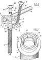
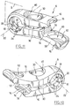
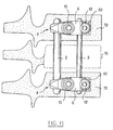
- the system comprises in the first embodiment an elongate connecting rod 2 with circular section and several subassemblies 4 to connector capable of being attached to it.
- Each of these subsets including two are visible in Figure 1 and only one is visible in FIG. 2, comprises a connector 6, a first vertebral screw or main screw 8, a screw of tightening 10, a second vertebral screw or screw secondary 12, and a ring 13.
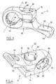
- the connector 6 comprises two branches 16 extending facing and distance from each other by giving the connector a general profile in "U".
- Connector 6 has a plane of symmetry S perpendicular to the width of the branches 16 and parallel to their length.
- the connector at the level of the birth of the branches 16, the connector has two cylindrical inner faces coaxial 18, 20 axis 22 perpendicular to the plane "S" and of different radii, the face 20 of larger radius is in two parts disjointed and extends from on the other side of the face 18 of smaller radius, which is crossed by the plane "S". Both sides 18, 20 form at their junctions two circular ridges 24 of axis 22.
- the ring 13 has a cylindrical inner face 26 and a coaxial outer spherical face 28.
- the face internal cylindrical 26 has a radius approximately equal to that of the rod 2 so that the ring 13, slotted on a side along its axis, can be received by adjustment sliding on the rod.
- the ring 13 can be housed between the branches 16 facing the faces cylindrical 18, 20.
- the spherical outer face 28 of the ring has a radius adapted so that in this position, the edges 24 of the connector 6 are in linear contact with the spherical outer face 28 of the ring 13 and he serve as supports.
- the angular position of the rod 2 threaded in the ring 13 can be set in two planes perpendicular to each other over an amplitude for example 15 ° on either side of an average position of the stem in which the stem is perpendicular to the plan "S".
- the branches 16 have two recesses respective cylindrical cylinders which are in this case through holes 30 extending coaxially in look at each other.
- the main screw 8 is a screw vertebral bicortical and presents a threaded body to this end in a manner known per se. She presents a head 32 having a smooth cylindrical outer face 34. junction between the head and the body, the screw has a annular flange 36 having a flat underside perpendicular to a longitudinal axis of the screw and a frustoconical upper face 38 with the most narrow truncated cone located on the side of the head 32 of the opinion.
- the head 32 has a coaxial threaded orifice 39 to the body of the screw and, formed in the threaded face of orifice 39, a non-circular shape such as a hexagonal hexagonal print.
- the clamping screw 10 has a threaded body 42 capable of forming a connection screw-nut with this orifice 39, and a screw head 44 in which a six-sided hexagonal pattern is formed sections.
- the head 44 has a spherical lower outer surface convex 46 whose narrowest section is located towards the tip of the screw.
- the two branches 16 are able to be threaded simultaneously on the head 32 of the main screw 8 introduced from the lower branch against which the upper face 38 of the flange 36 comes in abutment.
- the tightening screw 10 is then inserted into the head 32 of the main screw 8 from the branch upper 16.
- the tightening of the screw 10 in the head 32 of the main screw 8 causes the approximation of 16 branches of each other and the friction lock of the rod 2 in the chosen position with respect to the connector 6.
- the orifice 30 of the lower branch 16 has an edge lower, opposite to the upper branch and intended for to be on the side of the vertebra, presenting an impression spherical concave 40 intended to come into contact with the upper face 38 of the flange 36 to make by friction locking a rotation of the connector 6 by relative to the axis of the main screw 8.
- the orifice 30 of the upper branch 16 has an upper edge, opposite to the lower branch and intended to be opposed to the vertebra with concave spherical imprint 40 intended to come into contact with the underside spherical convex 46 of the head 44 of the clamping screw 10 and to fix it and the screw 8 by adjusting the angular orientation of the main screw 8 with respect to the connector.
- the extension 50 has a recess under the shape of a through hole 52.
- the lower branch 16 is bent at the level of the extension 50 in a opposite direction to the upper branch 16 so that the axes of the openings 30 and 52 that it carries are not not quite parallel.
- the secondary screw 12 is a vertebral screw, here monocortical, presenting a body threaded and a head 56 with a spherical underside convex 58, the narrowest section of which is side of the body. His head has a six-footprint sections.
- the orifice 52 of the extension has an upper edge, oriented on the side of the other branch 16 and intended to be opposite the vertebra, having a spherical imprint concave 60 intended to come into contact with the face convex spherical lower 58 of the head 56 of the screw secondary 12 by adjusting the orientation angle of this screw relative to the connector 6.
- the lower branch 16 can be bent for accentuate or reduce curvature in order to better fit the shape of the anterior part of his vertebra of destination. Once bent, this branch 16 is no longer stressed in flexion since it is attached to the vertebra with two screws 8, 12 along its length.
- the two main screws 8 and 12 are self-tapping and include bone threads.
- the main screw 8 does not have a hexagonal imprint in its threaded orifice 39, but the flange 36 has a shape hexagonal or has two parallel flats and diametrically opposed to each other that can cooperate with a spanner to put this screw 8 into rotation relative to the connector 6.
- connector 6 is one single piece.
- the different parts of the system are in biocompatible metal.
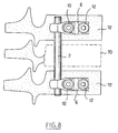
- the rod 2 After having instrumented the two vertebrae adjacent 72, the rod 2 is positioned in the rings connectors 6 and we adjust its angular position on each subset. Final tightening takes place thanks to the clamping screw 10 which fits into the main screw 8 and thus compresses the connector 6 to tighten the rod.
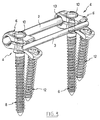
- the system is very close to that of first mode. It differs however in the presence a second elongated connecting rod 3 or rod circular section, and by adapting the connector 6 upon receipt of this second rod.
- the ring 13 is received on the first rod or rod main 2.
- the two connecting rods 2, 3 each have a rectilinear shape profiled here circular profile.
- the secondary rod 3 has a section, transversely to its longitudinal axis, of a diameter smaller than that of the main stem 2.
- the main stem 2 will have for example a diameter of 6 mm.
- the diameter of the stem Secondary 3 will be between 30% and 80% of the diameter of the main stem 2. This small diameter allows the surgeon to choose the curvature of the secondary stem 3 which corresponds to that of the floor of the spine instrumented.
- the rings 13 allow a relative angulation between the two 6 connectors, the main stem 2 does not need to be bent. It can therefore have a diameter important to be very robust.
- the branches 16 of the connector have cylindrical imprints or jaws 74 respectively, arranged in the faces of the branches facing one another.
- the impressions 74 extend opposite one another and have axes parallel to each other, and perpendicular to the plane of symmetry S.
- the impression 74 extends to a free end of the branch so that the orifice 30 is interposed between the faces 18, 20 of a part, and the imprint 74, on the other hand.
- the impression 74 extends between the two orifices 30 and 52, at the birth of the extension 50. It is contiguous to the orifice 52 so that it bites on its edge 60.
- the secondary rod 3 is intended to be received in the imprint 74 of the lower branch 16 in a single angular position relative to the connector, perpendicular to the S plane of symmetry.
- the imprint 74 of the upper branch comes into contact with the secondary rod 3 which is thus in contact surface with each of the two footprints perform a friction lock on the secondary rod 3 relative to the connector 6, which are thus rigidly fixed to each other.
- the secondary rod 3 is placed in the impression 74 of the lower branch after the secondary screw 12 was introduced into port 52.
- the position of the footprint 74 of the lower branch makes sure that the secondary rod 3 then extends in the path of the head of the secondary screw 12 for its disengagement of the connector and its exit from the orifice 52. By therefore, once the secondary rod 3 is attached to the connector, the secondary screw 12 can no longer be separated from the connector.
- the upper branch 16 of the connector presents its free end a notch 76 that bites on the footprint 74 to which it is contiguous and facilitates the operation by means of a tool of the secondary screw 12 despite the clutter of the upper branch.
- Putting the system in the second mode is similar to that of the first mode system.
- the setting up the main screw 8 and secondary 12 is unchanged.
- the main rod 2 After having instrumented the two vertebrae 72, the main rod 2 is positioned in the rings 13 of the connectors 6 and the position is adjusted angular of each subset 4 with respect to this 2.
- the secondary rod 3 is then introduced into the fingerprints 74 of the connectors 6 after having previously bent manually to get the curvature required at the corresponding spinal stage. In case of default, this rod 3 can be removed to correct its curvature then replaced.
- Figure 9 shows the system before tightening the branches. Final tightening takes place thanks to the clamping screw 10 which fits into the screw main 8 and thus compresses the connector 6 to squeeze both branches 16 towards each other.
- the connectors 6, at least two in number, are rigidly simultaneously attached each to the same main rods and secondary stem.
- the branch extended may be the one intended to be the most distant from the vertebra.
- the characteristics can be implemented relating to the presence of the two vertebral screws on the connector independently of those relating to the presence of the main and secondary stems, and reciprocally.
Landscapes
- Health & Medical Sciences (AREA)
- Orthopedic Medicine & Surgery (AREA)
- Life Sciences & Earth Sciences (AREA)
- Neurology (AREA)
- Surgery (AREA)
- Heart & Thoracic Surgery (AREA)
- Engineering & Computer Science (AREA)
- Biomedical Technology (AREA)
- Nuclear Medicine, Radiotherapy & Molecular Imaging (AREA)
- Medical Informatics (AREA)
- Molecular Biology (AREA)
- Animal Behavior & Ethology (AREA)
- General Health & Medical Sciences (AREA)
- Public Health (AREA)
- Veterinary Medicine (AREA)
- Surgical Instruments (AREA)
- Prostheses (AREA)
- Orthopedics, Nursing, And Contraception (AREA)
Claims (17)
- Wirbelsäulen-Osteosynthesesystem besonders für die vordere Fixierung, das ein längliches Verbindungselement (2), eine erste Wirbelschraube (8) und ein Anschlußstück (6) umfaßt, das zwei Schenkel (16) umfaßt, die geeignet sind, das Verbindungselement (2) zwischeneinander einzuklemmen, wobei mindestens ein erster der Schenkel (16) geeignet ist, auf der ersten Wirbelschraube (8) in Eingriff gebracht zu werden, wobei das System eine zweite Wirbelschraube (12) umfaßt, und wobei der erste Schenkel (16) eine Verlängerung (50) umfaßt, die geeignet ist, auf der zweiten Schraube (12) in Eingriff gebracht zu werden, dadurch gekennzeichnet, daß die Verlängerung derart angeordnet ist, daß sich die beiden Schrauben von ein und derselben Seite des Verbindungselementes aus erstrecken.
- System nach Anspruch 1, dadurch gekennzeichnet, daß die Verlängerung (50) eine Ausnehmung (52) zur Aufnahme der zweiten Schraube (12) aufweist.
- System nach Anspruch 2, dadurch gekennzeichnet, daß die Verlängerung (50) eine kugelige Vertiefung (60) an einem Rand der Ausnehmung (52) aufweist, der dazu geeignet ist, vom Wirbel wegzuweisen.
- System nach einem der Ansprüche 1 bis 3, dadurch gekennzeichnet, daß einer der Schenkel (16), der dazu bestimmt ist, vom Wirbel wegzuweisen, eine Ausnehmung (30) zur Aufnahme der ersten Schraube (8) und eine kugelige Vertiefung (40) an einem Rand der Ausnehmung aufweist, der dazu bestimmt ist, vom Wirbel wegzuweisen.
- System nach einem der Ansprüche 1 bis 4, dadurch gekennzeichnet, daß der längliche Schenkel (16) geeignet ist, von Hand, besonders mittels eines Werkzeugs, gebogen zu werden.
- System nach einem der Ansprüche 1 bis 5, dadurch gekennzeichnet, daß die erste Schraube (8) einen Kopf (32) und einen Kragen (36) umfaßt, der vom Kopf unterschieden ist und geeignet ist, mit einem der Schenkel (16) zusammenzuwirken, um das Anschlußstück (6) bezüglich der ersten Schraube (8) drehunbeweglich zu machen.
- System nach Anspruch 6, dadurch gekennzeichnet, daß der Kragen (36) eine insbesondere konische Fläche (38) aufweist, die geeignet ist, das Anschlußstück (6) durch Reibung unbeweglich zu machen.
- System nach einem der Ansprüche 1 bis 7, dadurch gekennzeichnet, daß die erste Schraube (8) eine mit Gewinde versehene Öffnung (39) aufweist, und daß das System eine Klemmschraube (10) umfaßt, die geeignet ist, eine Schrauben-Mutter-Verbindung mit dieser Öffnung zu bilden und gegen einen der Schenkel (16) anzuliegen, der dazu bestimmt ist, vom Wirbel wegzuweisen, um die Schenkel (16) festzuklemmen.
- System nach einem der Ansprüche 1 bis 8, dadurch gekennzeichnet, daß es einen Ring (13) umfaßt, der geeignet ist, auf dem Verbindungselement (2) aufgezogen zu werden und zwischen den Schenkeln (16) aufgenommen zu werden, und daß das Verbindungsstück (6) und der Ring (13) dazu ausgebildet sind, eine Regulierung der Richtung des Verbindungselementes (2) in zwei zueinander senkrechten Ebenen vor dem Festklemmen der Schenkel (16) zu gestatten.
- System nach einem der Ansprüche 1 bis 9, dadurch gekennzeichnet, daß die beiden Schenkel (16) Teil ein und desselben Stückes (6) bilden, das elastisch verformbar ist, um die Schenkel aneinander anzunähern.
- System nach einem der Ansprüche 1 bis 10, dadurch gekennzeichnet, daß das Verbindungsstück (6) dazu geeignet ist, an der Wirbelschraube (8) und am ersten Verbindungselement (2) befestigt zu werden, indem man eine Winkellage des Verbindungselements bezüglich des Verbindungsstückes wählt.
- System nach einem der Ansprüche 1 bis 11, dadurch gekennzeichnet, daß es ein zweites, längliches Verbindungselement (3) umfaßt, wobei das Anschlußstück (6) geeignet ist, gleichzeitig an den beiden Verbindungselementen (2, 3) befestigt zu werden.
- System nach Anspruch 12, dadurch gekennzeichnet, daß es derart eingerichtet ist, daß das zweite Verbindungselement (3) nur in einer einzigen Winkellage in Bezug auf das Verbindungsstück (6) an diesem befestigt werden kann.
- System nach Anspruch 12 oder 13, dadurch gekennzeichnet, daß das zweite Verbindungselement (3) einen schwächeren Biegewiderstand aufweist als das erste Verbindungselement (2).
- System nach einem der Ansprüche 12 bis 14, dadurch gekennzeichnet, daß die beiden Schenkel (16) dazu geeignet sind, gleichzeitig die zwei Verbindungselemente (2, 3) festzuklemmen.
- System nach einem der Ansprüche 12 bis 15, dadurch gekennzeichnet, daß es derart angeordnet ist, daß das zweite Verbindungselement (3) dann, wenn es am Anschlußstück (6) befestigt ist, sich für ein Lösen des Anschlußstücks (6) in einer Bewegungsbahn der zweiten Wirbelschraube (12) erstreckt.
- System nach einem der Ansprüche 12 bis 16, dadurch gekennzeichnet, daß es ein zweites Anschlußstück umfaßt, wobei die beiden Anschlußstücke (6) geeignet sind, gleichzeitig jeweils an den beiden Verbindungselementen (2, 3) befestigt zu werden.
Applications Claiming Priority (5)
| Application Number | Priority Date | Filing Date | Title |
|---|---|---|---|
| FR9805387A FR2778086B1 (fr) | 1998-04-29 | 1998-04-29 | Systeme d'osteosynthese rachidienne pour une fixation anterieure |
| FR9805387 | 1998-04-29 | ||
| FR9812662A FR2784282B1 (fr) | 1998-10-09 | 1998-10-09 | Systeme d'osteosynthese rachidienne a rigidite amelioree |
| FR9812662 | 1998-10-09 | ||
| PCT/FR1999/001019 WO1999055246A1 (fr) | 1998-04-29 | 1999-04-29 | Systeme d'osteosynthese rachidienne pour une fixation anterieure |
Publications (2)
| Publication Number | Publication Date |
|---|---|
| EP1075223A1 EP1075223A1 (de) | 2001-02-14 |
| EP1075223B1 true EP1075223B1 (de) | 2005-11-16 |
Family
ID=26234298
Family Applications (2)
| Application Number | Title | Priority Date | Filing Date |
|---|---|---|---|
| EP99916956A Expired - Lifetime EP1075224B1 (de) | 1998-04-29 | 1999-04-29 | Wirbelsäulen-osteosynthesesystem mit spannvorrichtung, insbesondere zur vorderen fixierung |
| EP99916955A Expired - Lifetime EP1075223B1 (de) | 1998-04-29 | 1999-04-29 | Wirbelsäulen-osteosynthesesystem insbesondere zur vorderen fixierung |
Family Applications Before (1)
| Application Number | Title | Priority Date | Filing Date |
|---|---|---|---|
| EP99916956A Expired - Lifetime EP1075224B1 (de) | 1998-04-29 | 1999-04-29 | Wirbelsäulen-osteosynthesesystem mit spannvorrichtung, insbesondere zur vorderen fixierung |
Country Status (10)
| Country | Link |
|---|---|
| US (4) | US6569164B1 (de) |
| EP (2) | EP1075224B1 (de) |
| JP (2) | JP4245806B2 (de) |
| KR (2) | KR20010043166A (de) |
| AT (2) | ATE233521T1 (de) |
| AU (2) | AU759236B2 (de) |
| CA (2) | CA2330802A1 (de) |
| DE (3) | DE69905707T2 (de) |
| ES (1) | ES2155427T3 (de) |
| WO (2) | WO1999055246A1 (de) |
Families Citing this family (209)
| Publication number | Priority date | Publication date | Assignee | Title |
|---|---|---|---|---|
| US6206922B1 (en) * | 1995-03-27 | 2001-03-27 | Sdgi Holdings, Inc. | Methods and instruments for interbody fusion |
| US6569164B1 (en) * | 1998-04-29 | 2003-05-27 | Stryker Spine | Spinal osteosynthesis system for anterior fixation |
| US8323341B2 (en) | 2007-09-07 | 2012-12-04 | Intrinsic Therapeutics, Inc. | Impaction grafting for vertebral fusion |
| WO2002054978A2 (en) * | 1999-08-18 | 2002-07-18 | Intrinsic Orthopedics Inc | Devices and method for nucleus pulposus augmentation and retention |
| US7998213B2 (en) | 1999-08-18 | 2011-08-16 | Intrinsic Therapeutics, Inc. | Intervertebral disc herniation repair |
| US7717961B2 (en) | 1999-08-18 | 2010-05-18 | Intrinsic Therapeutics, Inc. | Apparatus delivery in an intervertebral disc |
| US6883520B2 (en) * | 1999-08-18 | 2005-04-26 | Intrinsic Therapeutics, Inc. | Methods and apparatus for dynamically stable spinal implant |
| WO2009033100A1 (en) * | 2007-09-07 | 2009-03-12 | Intrinsic Therapeutics, Inc. | Bone anchoring systems |
| WO2004100841A1 (en) | 1999-08-18 | 2004-11-25 | Intrinsic Therapeutics, Inc. | Devices and method for augmenting a vertebral disc nucleus |
| US7972337B2 (en) | 2005-12-28 | 2011-07-05 | Intrinsic Therapeutics, Inc. | Devices and methods for bone anchoring |
| WO2001030248A1 (en) * | 1999-10-22 | 2001-05-03 | Reiley Mark A | Facet arthroplasty devices and methods |
| JP3383257B2 (ja) | 2000-03-10 | 2003-03-04 | 株式会社ロバート・リード商会 | ロッド固定装置 |
| JP2004516040A (ja) | 2000-06-30 | 2004-06-03 | リトラン、スティーブン | 多軸継手装置及び方法 |
| US7166073B2 (en) | 2000-09-29 | 2007-01-23 | Stephen Ritland | Method and device for microsurgical intermuscular spinal surgery |
| US6692434B2 (en) | 2000-09-29 | 2004-02-17 | Stephen Ritland | Method and device for retractor for microsurgical intermuscular lumbar arthrodesis |
| US6626906B1 (en) * | 2000-10-23 | 2003-09-30 | Sdgi Holdings, Inc. | Multi-planar adjustable connector |
| US7651516B2 (en) * | 2000-12-01 | 2010-01-26 | Spinevision S.A. | Connection assembly for the field of spinal osteosynthesis and method for using at least one such assembly |
| US6702817B2 (en) * | 2001-01-19 | 2004-03-09 | Aesculap Ag & Co. Kg | Locking mechanism for a bone screw |
| FR2821131B1 (fr) * | 2001-02-22 | 2003-12-12 | Spine Next Sa | Vis a fixation |
| US6991632B2 (en) * | 2001-09-28 | 2006-01-31 | Stephen Ritland | Adjustable rod and connector device and method of use |
| AU2002327801B2 (en) | 2001-09-28 | 2008-03-06 | Stephen Ritland | Connection rod for screw or hook polyaxial system and method of use |
| FR2831420B1 (fr) * | 2001-10-30 | 2004-07-16 | Vitatech | Appareil de maintien du rachis a assemblage par coincement |
| US7763047B2 (en) * | 2002-02-20 | 2010-07-27 | Stephen Ritland | Pedicle screw connector apparatus and method |
| FR2836368B1 (fr) * | 2002-02-25 | 2005-01-14 | Spine Next Sa | Dispositif de liaison sequentiel |
| US6966910B2 (en) * | 2002-04-05 | 2005-11-22 | Stephen Ritland | Dynamic fixation device and method of use |
| EP2457528A1 (de) | 2002-05-08 | 2012-05-30 | Stephen Ritland | Dynamische Befestigungsvorrichtung und Verwendungsverfahren dafür |
| FR2842093B1 (fr) * | 2002-07-12 | 2005-04-15 | Scient X | Dispositif d'ancrage osseux avec articulation spherique |
| US20040015166A1 (en) * | 2002-07-22 | 2004-01-22 | Gorek Josef E. | System and method for stabilizing the spine by securing spine stabilization rods in crossed disposition |
| FR2842724B1 (fr) | 2002-07-23 | 2005-05-27 | Spine Next Sa | Systeme de fixation vertebrale |
| DE50206605D1 (de) * | 2002-09-04 | 2006-06-01 | Aesculap Ag & Co Kg | Orthopädische fixationseinrichtung |
| US7615070B2 (en) * | 2002-10-11 | 2009-11-10 | Spineco, Inc. | Electro-stimulation and medical delivery device |
| US20040111088A1 (en) * | 2002-12-06 | 2004-06-10 | Picetti George D. | Multi-rod bone attachment member |
| US8262571B2 (en) | 2003-05-22 | 2012-09-11 | Stephen Ritland | Intermuscular guide for retractor insertion and method of use |
| US7951176B2 (en) | 2003-05-30 | 2011-05-31 | Synthes Usa, Llc | Bone plate |
| US7270665B2 (en) * | 2003-06-11 | 2007-09-18 | Sdgi Holdings, Inc. | Variable offset spinal fixation system |
| US11259851B2 (en) | 2003-08-26 | 2022-03-01 | DePuy Synthes Products, Inc. | Bone plate |
| DE20321552U1 (de) | 2003-08-26 | 2007-12-27 | Synthes Gmbh | Knochenplatte |
| US20050049595A1 (en) | 2003-09-03 | 2005-03-03 | Suh Sean S. | Track-plate carriage system |
| US7909860B2 (en) | 2003-09-03 | 2011-03-22 | Synthes Usa, Llc | Bone plate with captive clips |
| CN1849098A (zh) * | 2003-09-04 | 2006-10-18 | Sdgi控股股份有限公司 | 使用杆-板前路系统校正脊柱变形的方法 |
| KR101050877B1 (ko) * | 2003-09-08 | 2011-07-20 | 신세스 게엠바하 | 뼈 고정 장치 |
| DE20314297U1 (de) * | 2003-09-12 | 2003-11-20 | AlloCon GmbH, 42929 Wermelskirchen | Knochenschraube |
| US8070785B2 (en) | 2003-09-16 | 2011-12-06 | Spineco, Inc. | Bone anchor prosthesis and system |
| AU2003271507B2 (en) * | 2003-10-30 | 2009-04-09 | Synthes Gmbh | Bone plate |
| US7722650B2 (en) * | 2003-11-14 | 2010-05-25 | Ashman Richard B | Variable angle spinal implant connection assembly |
| US11291484B2 (en) | 2004-01-26 | 2022-04-05 | DePuy Synthes Products, Inc. | Highly-versatile variable-angle bone plate system |
| US8574268B2 (en) | 2004-01-26 | 2013-11-05 | DePuy Synthes Product, LLC | Highly-versatile variable-angle bone plate system |
| US7637928B2 (en) * | 2004-01-26 | 2009-12-29 | Synthes Usa, Llc | Variable angle locked bone fixation system |
| US20050182317A1 (en) * | 2004-01-29 | 2005-08-18 | Haddad Souheil F. | Method and apparatus for locating medical devices in tissue |
| US7862594B2 (en) | 2004-02-27 | 2011-01-04 | Custom Spine, Inc. | Polyaxial pedicle screw assembly |
| US7819902B2 (en) * | 2004-02-27 | 2010-10-26 | Custom Spine, Inc. | Medialised rod pedicle screw assembly |
| US7163539B2 (en) | 2004-02-27 | 2007-01-16 | Custom Spine, Inc. | Biased angle polyaxial pedicle screw assembly |
| US7892257B2 (en) | 2004-02-27 | 2011-02-22 | Custom Spine, Inc. | Spring loaded, load sharing polyaxial pedicle screw assembly and method |
| WO2005096973A1 (en) * | 2004-04-08 | 2005-10-20 | Tresona Instrument Ab | Device for correcting and stabilising a scoliosis curvature |
| US7914556B2 (en) * | 2005-03-02 | 2011-03-29 | Gmedelaware 2 Llc | Arthroplasty revision system and method |
| US7901435B2 (en) * | 2004-05-28 | 2011-03-08 | Depuy Spine, Inc. | Anchoring systems and methods for correcting spinal deformities |
| US8034085B2 (en) * | 2004-05-28 | 2011-10-11 | Depuy Spine, Inc. | Non-fusion spinal correction systems and methods |
| US8114158B2 (en) | 2004-08-03 | 2012-02-14 | Kspine, Inc. | Facet device and method |
| DE102004046163A1 (de) | 2004-08-12 | 2006-02-23 | Columbus Trading-Partners Pos und Brendel GbR (vertretungsberechtigte Gesellschafter Karin Brendel, 95503 Hummeltal und Bohumila Pos, 95445 Bayreuth) | Kindersitz für Kraftfahrzeuge |
| EP1799134A4 (de) * | 2004-09-14 | 2011-03-09 | Spineco Inc | Implantatvorrichtung |
| US7455639B2 (en) | 2004-09-20 | 2008-11-25 | Stephen Ritland | Opposing parallel bladed retractor and method of use |
| US20060084976A1 (en) | 2004-09-30 | 2006-04-20 | Depuy Spine, Inc. | Posterior stabilization systems and methods |
| US7766940B2 (en) | 2004-12-30 | 2010-08-03 | Depuy Spine, Inc. | Posterior stabilization system |
| US7896906B2 (en) * | 2004-12-30 | 2011-03-01 | Depuy Spine, Inc. | Artificial facet joint |
| US8092496B2 (en) | 2004-09-30 | 2012-01-10 | Depuy Spine, Inc. | Methods and devices for posterior stabilization |
| US20060095037A1 (en) * | 2004-10-29 | 2006-05-04 | Jones Bryan S | Connector assemblies for connecting a bone anchor to a fixation element |
| US7594924B2 (en) * | 2005-03-03 | 2009-09-29 | Accelerated Innovation, Llc | Spinal stabilization using bone anchor seat and cross coupling with improved locking feature |
| WO2006096351A1 (en) * | 2005-03-03 | 2006-09-14 | Accelerated Innovation, Llc | Spinal stabilization using bone anchor and anchor seat with tangential locking feature |
| CN103479419B (zh) | 2005-04-08 | 2017-04-12 | 帕拉迪格脊骨有限责任公司 | 棘突间脊椎和腰骶稳定装置及使用方法 |
| US9942511B2 (en) | 2005-10-31 | 2018-04-10 | Invention Science Fund I, Llc | Preservation/degradation of video/audio aspects of a data stream |
| US7678112B2 (en) * | 2005-04-26 | 2010-03-16 | Warsaw Orthopedic, Inc. | Open dorsal adjusting connector |
| CA2609386A1 (en) * | 2005-05-23 | 2006-11-30 | Availvs Corporation | Method for measuring luminance of light-emitting object and device therefor |
| US7608081B2 (en) * | 2005-05-23 | 2009-10-27 | Custom Spine, Inc. | Rod reducer |
| WO2007012025A2 (en) | 2005-07-19 | 2007-01-25 | Stephen Ritland | Rod extension for extending fusion construct |
| US7628799B2 (en) | 2005-08-23 | 2009-12-08 | Aesculap Ag & Co. Kg | Rod to rod connector |
| DE102005044532A1 (de) * | 2005-09-16 | 2007-04-05 | Ulrich Gmbh & Co. Kg | Ventrale Platte |
| FR2890850B1 (fr) | 2005-09-20 | 2009-04-17 | Abbott Spine Sa | Systeme de fixation vertebrale |
| FR2890851B1 (fr) * | 2005-09-21 | 2008-06-20 | Abbott Spine Sa | Ancillaire de mise en tension d'un lien souple. |
| US8075597B2 (en) * | 2005-09-23 | 2011-12-13 | Applied Orthopaedics Llc | Apparatus for retaining vertebrae |
| US7927359B2 (en) | 2005-10-06 | 2011-04-19 | Paradigm Spine, Llc | Polyaxial screw |
| EP1931269A1 (de) * | 2005-10-07 | 2008-06-18 | Alphatec Spine, Inc. | Querstangenverbinder |
| US7803174B2 (en) * | 2005-11-04 | 2010-09-28 | Warsaw Orthopedic, Inc. | Dorsal adjusting multi-rod connector |
| US8029546B2 (en) * | 2005-12-15 | 2011-10-04 | Warsaw Orthopedic, Inc. | Variable angle offset spinal connector assembly |
| US20070191844A1 (en) * | 2006-01-31 | 2007-08-16 | Sdgi Holdings, Inc. | In-series, dual locking mechanism device |
| US7585299B2 (en) * | 2006-02-17 | 2009-09-08 | Warsaw Orthopedic, Inc. | Dorsal adjusting spinal connector assembly |
| US8262696B2 (en) * | 2006-02-24 | 2012-09-11 | Medical Design, LLC | Multilevel facet/laminar fixation system |
| WO2007123920A2 (en) * | 2006-04-18 | 2007-11-01 | Joseph Nicholas Logan | Spinal rod system |
| US7794501B2 (en) * | 2006-04-27 | 2010-09-14 | Wasaw Orthopedic, Inc. | Expandable intervertebral spacers and methods of use |
| US20080015576A1 (en) * | 2006-04-28 | 2008-01-17 | Whipple Dale E | Large diameter bone anchor assembly |
| US8133262B2 (en) * | 2006-04-28 | 2012-03-13 | Depuy Spine, Inc. | Large diameter bone anchor assembly |
| US20080015596A1 (en) * | 2006-04-28 | 2008-01-17 | Whipple Dale E | Large diameter multiple piece bone anchor assembly |
| US8361129B2 (en) * | 2006-04-28 | 2013-01-29 | Depuy Spine, Inc. | Large diameter bone anchor assembly |
| US8172882B2 (en) | 2006-06-14 | 2012-05-08 | Spartek Medical, Inc. | Implant system and method to treat degenerative disorders of the spine |
| US7959564B2 (en) | 2006-07-08 | 2011-06-14 | Stephen Ritland | Pedicle seeker and retractor, and methods of use |
| KR101166614B1 (ko) * | 2006-09-18 | 2012-07-18 | 워쏘우 오르쏘페딕 인코포레이티드 | 정형외과용 플레이트 시스템 |
| US8672983B2 (en) * | 2006-09-18 | 2014-03-18 | Warsaw Orthopedic, Inc. | Orthopedic plate system |
| EP2047813A1 (de) | 2007-10-11 | 2009-04-15 | Abbott Spine | Knochenbefestigungssystem und Verfahren zu dessen Verwendung |
| US20080086130A1 (en) * | 2006-10-06 | 2008-04-10 | Depuy Spine, Inc. | Torsionally stable fixation |
| US7744632B2 (en) | 2006-12-20 | 2010-06-29 | Aesculap Implant Systems, Inc. | Rod to rod connector |
| US8747445B2 (en) | 2007-01-15 | 2014-06-10 | Ebi, Llc | Spinal fixation device |
| US10603077B2 (en) * | 2007-04-12 | 2020-03-31 | Globus Medical, Inc. | Orthopedic fastener for stabilization and fixation |
| US8092501B2 (en) | 2007-06-05 | 2012-01-10 | Spartek Medical, Inc. | Dynamic spinal rod and method for dynamic stabilization of the spine |
| US8109970B2 (en) | 2007-06-05 | 2012-02-07 | Spartek Medical, Inc. | Deflection rod system with a deflection contouring shield for a spine implant and method |
| US8021396B2 (en) | 2007-06-05 | 2011-09-20 | Spartek Medical, Inc. | Configurable dynamic spinal rod and method for dynamic stabilization of the spine |
| US8083772B2 (en) * | 2007-06-05 | 2011-12-27 | Spartek Medical, Inc. | Dynamic spinal rod assembly and method for dynamic stabilization of the spine |
| US8048115B2 (en) | 2007-06-05 | 2011-11-01 | Spartek Medical, Inc. | Surgical tool and method for implantation of a dynamic bone anchor |
| US8114134B2 (en) | 2007-06-05 | 2012-02-14 | Spartek Medical, Inc. | Spinal prosthesis having a three bar linkage for motion preservation and dynamic stabilization of the spine |
| US7963978B2 (en) | 2007-06-05 | 2011-06-21 | Spartek Medical, Inc. | Method for implanting a deflection rod system and customizing the deflection rod system for a particular patient need for dynamic stabilization and motion preservation spinal implantation system |
| US8048121B2 (en) | 2007-06-05 | 2011-11-01 | Spartek Medical, Inc. | Spine implant with a defelction rod system anchored to a bone anchor and method |
| US7942900B2 (en) | 2007-06-05 | 2011-05-17 | Spartek Medical, Inc. | Shaped horizontal rod for dynamic stabilization and motion preservation spinal implantation system and method |
| US8162979B2 (en) | 2007-06-06 | 2012-04-24 | K Spine, Inc. | Medical device and method to correct deformity |
| US20090076550A1 (en) * | 2007-09-18 | 2009-03-19 | Ortho Development Corporation | Spinal fixation system connectors |
| FR2921248A1 (fr) * | 2007-09-25 | 2009-03-27 | Abbott Spine Sa | Dispositif de serrage de deux portions d'une tresse et implant intervertebral comprenant une cale, une tresse et un tel dispositif de serrage |
| US8128635B2 (en) * | 2007-10-23 | 2012-03-06 | Zimmer Spine S.A.S. | Bone fixation tensioning tool and method |
| ATE536824T1 (de) * | 2007-10-23 | 2011-12-15 | Zimmer Spine | Befestigungsvorrichtungen und stabilisierungssysteme mit diesen befestigungsvorrichtungen |
| EP2222239B1 (de) * | 2007-10-23 | 2015-07-08 | K2M, Inc. | Polyaxiale schraubenanordnung |
| US20140114359A1 (en) * | 2012-10-23 | 2014-04-24 | Nexus Spine, L.L.C. | Transverse connector and related methods |
| WO2009097624A2 (en) * | 2008-02-02 | 2009-08-06 | Texas Scottish Rite Hospital For Children | Spinal rod link reducer |
| US9579126B2 (en) | 2008-02-02 | 2017-02-28 | Globus Medical, Inc. | Spinal rod link reducer |
| US9345517B2 (en) | 2008-02-02 | 2016-05-24 | Globus Medical, Inc. | Pedicle screw having a removable rod coupling |
| US9050141B2 (en) | 2008-02-02 | 2015-06-09 | Texas Scottish Rite Hospital For Children | Pedicle screw |
| US8267979B2 (en) | 2008-02-26 | 2012-09-18 | Spartek Medical, Inc. | Load-sharing bone anchor having a deflectable post and axial spring and method for dynamic stabilization of the spine |
| US8083775B2 (en) | 2008-02-26 | 2011-12-27 | Spartek Medical, Inc. | Load-sharing bone anchor having a natural center of rotation and method for dynamic stabilization of the spine |
| US20100030224A1 (en) | 2008-02-26 | 2010-02-04 | Spartek Medical, Inc. | Surgical tool and method for connecting a dynamic bone anchor and dynamic vertical rod |
| US8337536B2 (en) | 2008-02-26 | 2012-12-25 | Spartek Medical, Inc. | Load-sharing bone anchor having a deflectable post with a compliant ring and method for stabilization of the spine |
| US8057515B2 (en) | 2008-02-26 | 2011-11-15 | Spartek Medical, Inc. | Load-sharing anchor having a deflectable post and centering spring and method for dynamic stabilization of the spine |
| US8097024B2 (en) | 2008-02-26 | 2012-01-17 | Spartek Medical, Inc. | Load-sharing bone anchor having a deflectable post and method for stabilization of the spine |
| US8333792B2 (en) | 2008-02-26 | 2012-12-18 | Spartek Medical, Inc. | Load-sharing bone anchor having a deflectable post and method for dynamic stabilization of the spine |
| US8211155B2 (en) | 2008-02-26 | 2012-07-03 | Spartek Medical, Inc. | Load-sharing bone anchor having a durable compliant member and method for dynamic stabilization of the spine |
| US8016861B2 (en) | 2008-02-26 | 2011-09-13 | Spartek Medical, Inc. | Versatile polyaxial connector assembly and method for dynamic stabilization of the spine |
| ATE515239T1 (de) * | 2008-04-24 | 2011-07-15 | Zimmer Spine | System zur stabilisierung von mindestens einem abschnitt der wirbelsäule |
| WO2009141393A1 (en) * | 2008-05-20 | 2009-11-26 | Zimmer Spine | System for stabilizing at least three vertebrae |
| ES2387512T3 (es) * | 2008-09-05 | 2012-09-25 | Biedermann Technologies Gmbh & Co. Kg | Dispositivo de estabilización para huesos, en particular para la columna vertebral |
| US20100087867A1 (en) * | 2008-10-03 | 2010-04-08 | Assaf Klein | Fastener assembly that fastens to pedicle screw |
| GB2465156B (en) | 2008-11-05 | 2012-09-26 | Dalmatic Lystrup As | Bone fixation system |
| US20100114171A1 (en) * | 2008-11-05 | 2010-05-06 | K2M, Inc. | Multi-planar spinal fixation assembly with locking element |
| GB2465335B (en) * | 2008-11-05 | 2012-08-15 | Dalmatic Lystrup As | Bone fixation device |
| US8828058B2 (en) | 2008-11-11 | 2014-09-09 | Kspine, Inc. | Growth directed vertebral fixation system with distractible connector(s) and apical control |
| US8545500B2 (en) * | 2008-11-19 | 2013-10-01 | Omni Surgical LLC | Bone fixation assembly |
| US9351767B2 (en) * | 2009-03-24 | 2016-05-31 | Life Spine, Inc. | Supplementary spinal fixation/stabilization apparatus with dynamic inter-vertebral connection |
| US8357183B2 (en) | 2009-03-26 | 2013-01-22 | Kspine, Inc. | Semi-constrained anchoring system |
| US8109976B2 (en) * | 2009-05-21 | 2012-02-07 | Warsaw Orthopedic, Inc. | Systems and methods for vertebral stabilization |
| US20100305615A1 (en) * | 2009-05-29 | 2010-12-02 | Custom Spine, Inc. | Multi-level Polyaxial Screw Connection Mechanism |
| EP2477566B1 (de) * | 2009-09-14 | 2017-03-22 | Synthes GmbH | Druckplatte mit veränderlichem winkel |
| US9168071B2 (en) | 2009-09-15 | 2015-10-27 | K2M, Inc. | Growth modulation system |
| US8568456B2 (en) | 2009-09-21 | 2013-10-29 | Globus Medical, Inc. | Transverse connector having a locking element for capturing multiple rods |
| US8361123B2 (en) | 2009-10-16 | 2013-01-29 | Depuy Spine, Inc. | Bone anchor assemblies and methods of manufacturing and use thereof |
| CN102695465A (zh) | 2009-12-02 | 2012-09-26 | 斯帕泰克医疗股份有限公司 | 结合具有可偏转柱和复合脊柱杆的骨锚固件的小轮廓脊柱假体 |
| FR2954905B1 (fr) | 2010-01-06 | 2012-12-28 | Implanet | Dispositif de fixation vertebrale |
| US8317834B2 (en) * | 2010-01-28 | 2012-11-27 | Warsaw Orthopedic, Inc. | Pre-assembled construct for insertion into a patient |
| WO2011106339A1 (en) | 2010-02-23 | 2011-09-01 | K2M, Inc. | Polyaxial bone screw assembly |
| US8758347B2 (en) * | 2010-03-19 | 2014-06-24 | Nextremity Solutions, Inc. | Dynamic bone plate |
| US10219842B2 (en) * | 2010-03-23 | 2019-03-05 | Scapa Flow, Llc | Cervical link system |
| WO2011127443A1 (en) * | 2010-04-08 | 2011-10-13 | Globus Medical, Inc. | Jointed rod |
| US8518085B2 (en) | 2010-06-10 | 2013-08-27 | Spartek Medical, Inc. | Adaptive spinal rod and methods for stabilization of the spine |
| US8777996B2 (en) | 2010-07-12 | 2014-07-15 | Globus Medical, Inc. | Interspinous ligament transverse connector |
| US8920471B2 (en) | 2010-07-12 | 2014-12-30 | K2M, Inc. | Transverse connector |
| EP2471476A1 (de) * | 2010-11-10 | 2012-07-04 | Zimmer Spine | Knochenanker |
| US9247964B1 (en) * | 2011-03-01 | 2016-02-02 | Nuasive, Inc. | Spinal Cross-connector |
| US9387013B1 (en) | 2011-03-01 | 2016-07-12 | Nuvasive, Inc. | Posterior cervical fixation system |
| US8992579B1 (en) * | 2011-03-08 | 2015-03-31 | Nuvasive, Inc. | Lateral fixation constructs and related methods |
| US9333009B2 (en) | 2011-06-03 | 2016-05-10 | K2M, Inc. | Spinal correction system actuators |
| US20130085534A1 (en) * | 2011-09-30 | 2013-04-04 | Nicolas Hainard | Connectors for a secondary bone anchor |
| US9468468B2 (en) | 2011-11-16 | 2016-10-18 | K2M, Inc. | Transverse connector for spinal stabilization system |
| US9468469B2 (en) | 2011-11-16 | 2016-10-18 | K2M, Inc. | Transverse coupler adjuster spinal correction systems and methods |
| US8920472B2 (en) | 2011-11-16 | 2014-12-30 | Kspine, Inc. | Spinal correction and secondary stabilization |
| WO2014172632A2 (en) | 2011-11-16 | 2014-10-23 | Kspine, Inc. | Spinal correction and secondary stabilization |
| US9451987B2 (en) | 2011-11-16 | 2016-09-27 | K2M, Inc. | System and method for spinal correction |
| US8430916B1 (en) | 2012-02-07 | 2013-04-30 | Spartek Medical, Inc. | Spinal rod connectors, methods of use, and spinal prosthesis incorporating spinal rod connectors |
| US9060815B1 (en) | 2012-03-08 | 2015-06-23 | Nuvasive, Inc. | Systems and methods for performing spine surgery |
| FR2989264B1 (fr) * | 2012-04-11 | 2014-05-09 | Medicrea International | Materiel d'osteosynthese vertebrale |
| US8828056B2 (en) | 2012-04-16 | 2014-09-09 | Aesculap Implant Systems, Llc | Rod to rod cross connector |
| US8771319B2 (en) | 2012-04-16 | 2014-07-08 | Aesculap Implant Systems, Llc | Rod to rod cross connector |
| WO2014011580A1 (en) * | 2012-07-12 | 2014-01-16 | DePuy Synthes Products, LLC | Device, kit and method for correction of spinal deformity |
| US9301782B2 (en) | 2012-09-04 | 2016-04-05 | Zimmer, Inc. | External fixation |
| US9924969B2 (en) | 2012-09-04 | 2018-03-27 | Zimmer, Inc. | External fixation |
| KR101424128B1 (ko) | 2012-12-28 | 2014-08-01 | 대구가톨릭대학교산학협력단 | 골 외고정 장치 |
| US8979898B2 (en) | 2013-02-20 | 2015-03-17 | K2M, Inc. | Iliosacral polyaxial screw |
| US9237907B2 (en) | 2013-03-05 | 2016-01-19 | Warsaw Orthopedic, Inc. | Spinal correction system and method |
| US10360139B2 (en) * | 2013-03-12 | 2019-07-23 | Entit Software Llc | Identifying transport-level encoded payloads |
| US9468471B2 (en) | 2013-09-17 | 2016-10-18 | K2M, Inc. | Transverse coupler adjuster spinal correction systems and methods |
| US9517089B1 (en) | 2013-10-08 | 2016-12-13 | Nuvasive, Inc. | Bone anchor with offset rod connector |
| FR3012032B1 (fr) | 2013-10-18 | 2015-12-11 | Implanet | Dispositif et systeme de fixation vertebrale pour maintien d'une vertebre sur une tige, methode de blocage d'une boucle avec un tel dispositif. |
| US9877755B2 (en) | 2014-03-17 | 2018-01-30 | Pega Medical, Inc. | Orthopedic apparatus for correcting rotational bone deformities and method for using the orthopedic apparatus |
| US9962187B2 (en) | 2014-08-11 | 2018-05-08 | Zimmer, Inc. | External fixation |
| US9579123B2 (en) * | 2014-09-19 | 2017-02-28 | Globus Medical, Inc. | Orthopedic stabilization devices and methods for installation thereof |
| US9649133B2 (en) * | 2014-11-11 | 2017-05-16 | Intrepid Orthopedics | Supplemental fixation screw |
| JP7029959B2 (ja) * | 2015-04-07 | 2022-03-04 | ケー2エム, インコーポレイテッド | 脊椎安定化装置 |
| US9763703B2 (en) | 2015-05-05 | 2017-09-19 | Degen Medical, Inc. | Cross connectors, kits, and methods |
| EP3310280B1 (de) | 2015-06-17 | 2024-10-23 | Zimmer, Inc. | Knöchel-fixierungsvorrichtung |
| US9968378B1 (en) * | 2015-07-22 | 2018-05-15 | University Of South Florida | Adaptation sphere saddle |
| HU5038U (hu) | 2015-09-25 | 2019-07-29 | Pelle Gyoergy Dr | Csontrögzítõ implantátum |
| US9962192B2 (en) | 2016-03-17 | 2018-05-08 | Medos International Sarl | Multipoint fixation implants |
| US10905476B2 (en) | 2016-09-08 | 2021-02-02 | DePuy Synthes Products, Inc. | Variable angle bone plate |
| US10820930B2 (en) | 2016-09-08 | 2020-11-03 | DePuy Synthes Products, Inc. | Variable angle bone plate |
| US10624686B2 (en) | 2016-09-08 | 2020-04-21 | DePuy Synthes Products, Inc. | Variable angel bone plate |
| US11026727B2 (en) | 2018-03-20 | 2021-06-08 | DePuy Synthes Products, Inc. | Bone plate with form-fitting variable-angle locking hole |
| US10898232B2 (en) | 2018-03-20 | 2021-01-26 | Medos International Sàrl | Multipoint fixation implants and related methods |
| US10772665B2 (en) | 2018-03-29 | 2020-09-15 | DePuy Synthes Products, Inc. | Locking structures for affixing bone anchors to a bone plate, and related systems and methods |
| US11013541B2 (en) | 2018-04-30 | 2021-05-25 | DePuy Synthes Products, Inc. | Threaded locking structures for affixing bone anchors to a bone plate, and related systems and methods |
| US10925651B2 (en) | 2018-12-21 | 2021-02-23 | DePuy Synthes Products, Inc. | Implant having locking holes with collection cavity for shavings |
| US10893894B2 (en) | 2019-04-24 | 2021-01-19 | Aesculap Implant Systems, Llc | Transverse coupling for surgical implant extensions |
| US11426210B2 (en) | 2019-09-25 | 2022-08-30 | Medos International Sàrl | Multipoint angled fixation implants for multiple screws and related methods |
| US11653953B2 (en) | 2019-10-11 | 2023-05-23 | Medos International Sarl | Implant receivers and connectors with grip grooves for rod fixation |
| JP7676711B2 (ja) | 2020-02-14 | 2025-05-15 | メドス・インターナショナル・エスエイアールエル | 統合された多点固定ねじ |
| US11707307B2 (en) | 2020-12-04 | 2023-07-25 | Globus Medical, Inc. | Systems and methods for treating rib fractures and osteotomies using implantation |
| US12102364B2 (en) | 2020-12-04 | 2024-10-01 | Globus Medical, Inc. | Systems and methods for treating rib fractures and osteotomies using implantation |
| US20220249131A1 (en) * | 2021-02-09 | 2022-08-11 | Rtg Scientific, Llc | Fastening devices, systems, and methods |
| AU2024232696A1 (en) * | 2023-03-06 | 2025-10-09 | Zimmer Biomet CMF and Thoracic, LLC | Pectus bar and stabilizer devices |
Family Cites Families (36)
| Publication number | Priority date | Publication date | Assignee | Title |
|---|---|---|---|---|
| FR2244446A1 (en) | 1973-09-21 | 1975-04-18 | Cotrel Yves | Traction device for scoliosis - tensioner rod clamped across vert. rods tensions vertebrae under max stress |
| US4289123A (en) | 1980-03-31 | 1981-09-15 | Dunn Harold K | Orthopedic appliance |
| US4987892A (en) * | 1989-04-04 | 1991-01-29 | Krag Martin H | Spinal fixation device |
| FR2651992B1 (fr) | 1989-09-18 | 1991-12-13 | Sofamor | Implant pour osteosynthese rachidienne dorso-lombaire anterieure destine a la correction de cyphoses. |
| FR2658413B1 (fr) | 1990-02-19 | 1997-01-03 | Sofamor | Dispositif d'osteosynthese pour la correction des deviations rachidiennes. |
| US5147380A (en) * | 1991-10-03 | 1992-09-15 | Cordis Corporation | Biopsy forceps device having improved locking means |
| FR2689750B1 (fr) | 1992-04-10 | 1997-01-31 | Eurosurgical | Element d'ancrage osseux et dispositif d'osteosynthese rachidienne incorporant de tels elements. |
| ATE124238T1 (de) | 1992-05-18 | 1995-07-15 | Pina Vertriebs Ag | Implantat für die wirbeläule. |
| US5324290A (en) | 1992-09-24 | 1994-06-28 | Danek Medical, Inc. | Anterior thoracolumbar plate |
| FR2697744B1 (fr) | 1992-11-10 | 1995-03-03 | Fabrication Mat Orthopedique S | Instrumentation d'ostéosynthèse rachidienne par voie antérieure. |
| US5702395A (en) * | 1992-11-10 | 1997-12-30 | Sofamor S.N.C. | Spine osteosynthesis instrumentation for an anterior approach |
| US5306275A (en) | 1992-12-31 | 1994-04-26 | Bryan Donald W | Lumbar spine fixation apparatus and method |
| EP0699056B1 (de) | 1993-05-18 | 1997-01-29 | Schäfer micomed GmbH | Knochenchirurgische haltevorrichtung |
| US5628740A (en) * | 1993-12-23 | 1997-05-13 | Mullane; Thomas S. | Articulating toggle bolt bone screw |
| US5662652A (en) * | 1994-04-28 | 1997-09-02 | Schafer Micomed Gmbh | Bone surgery holding apparatus |
| DE9412744U1 (de) | 1994-08-06 | 1995-12-07 | Schäfer micomed GmbH, 73614 Schorndorf | Knochenchirurgische Haltevorrichtung |
| DE4433360C2 (de) * | 1994-07-19 | 1996-12-12 | Schaefer Micomed Gmbh | Knochenchirurgische Haltevorrichtung |
| FR2724553B1 (fr) | 1994-09-15 | 1996-12-20 | Tornier Sa | Fixateur externe ou interne destine a la reparation des fractures ou des arthroplasties du squelette |
| US6004322A (en) * | 1994-10-25 | 1999-12-21 | Sdgi Holdings, Inc. | Modular pedicle screw system |
| US5620443A (en) | 1995-01-25 | 1997-04-15 | Danek Medical, Inc. | Anterior screw-rod connector |
| FR2731344B1 (fr) | 1995-03-06 | 1997-08-22 | Dimso Sa | Instrumentation rachidienne notamment pour tige |
| US5716355A (en) * | 1995-04-10 | 1998-02-10 | Sofamor Danek Group, Inc. | Transverse connection for spinal rods |
| US5613968A (en) | 1995-05-01 | 1997-03-25 | Lin; Chih-I | Universal pad fixation device for orthopedic surgery |
| US5683391A (en) | 1995-06-07 | 1997-11-04 | Danek Medical, Inc. | Anterior spinal instrumentation and method for implantation and revision |
| FR2743712B1 (fr) * | 1996-01-19 | 1998-04-30 | Louis Rene | Dispositif d'ancrage d'osteosynthese vertebrale posterieure |
| EP0959791B1 (de) | 1996-04-18 | 2003-08-27 | Tresona Instrument Ab | Vorrichtung zur korrektur und zur stabilisierung der abweichenden krümmung einer wirbelsäule |
| DE29712697U1 (de) | 1997-07-18 | 1997-09-25 | ENDOTEC Vertriebs- und Beratungsgesellschaft für Medizintechnik mbH, 51399 Burscheid | Wirbelsäulenfixateur |
| US5964769A (en) * | 1997-08-26 | 1999-10-12 | Spinal Concepts, Inc. | Surgical cable system and method |
| DE69721278T2 (de) * | 1997-12-17 | 2004-02-05 | Robert Lange | Apparat zur Stabilisierung bestimmter Wirbel der Wirbelsäule |
| EP0933065A1 (de) | 1998-02-02 | 1999-08-04 | Sulzer Orthopädie AG | Schwenkbares Befestigungssystem an einer Knochenschraube |
| US6569164B1 (en) * | 1998-04-29 | 2003-05-27 | Stryker Spine | Spinal osteosynthesis system for anterior fixation |
| FR2780631B1 (fr) | 1998-07-06 | 2000-09-29 | Dimso Sa | Dispositif d'osteosynthese rachidienne pour fixation anterieure avec plaque |
| US6136002A (en) * | 1999-02-05 | 2000-10-24 | Industrial Technology Research Institute | Anterior spinal fixation system |
| DE19914232B4 (de) | 1999-03-29 | 2012-08-30 | Signus Medizintechnik Gmbh | Vorrichtung zum Stabilisieren von Wirbelkörpern einer Wirbelsäule |
| US6328739B1 (en) * | 1999-05-04 | 2001-12-11 | Industrial Technology Research Institute | Enhanced spine fixation apparatus |
| DE19944120B4 (de) * | 1999-09-15 | 2008-08-28 | Ulrich Gmbh & Co. Kg | Knochenschraube zur winkelvariablen Verbindung mit einem Längsträger |
-
1999
- 1999-04-29 US US09/674,207 patent/US6569164B1/en not_active Expired - Fee Related
- 1999-04-29 AT AT99916956T patent/ATE233521T1/de not_active IP Right Cessation
- 1999-04-29 KR KR1020007012084A patent/KR20010043166A/ko not_active Withdrawn
- 1999-04-29 ES ES99916956T patent/ES2155427T3/es not_active Expired - Lifetime
- 1999-04-29 EP EP99916956A patent/EP1075224B1/de not_active Expired - Lifetime
- 1999-04-29 CA CA002330802A patent/CA2330802A1/fr not_active Abandoned
- 1999-04-29 EP EP99916955A patent/EP1075223B1/de not_active Expired - Lifetime
- 1999-04-29 DE DE69905707T patent/DE69905707T2/de not_active Expired - Lifetime
- 1999-04-29 DE DE69928389T patent/DE69928389T2/de not_active Expired - Lifetime
- 1999-04-29 WO PCT/FR1999/001019 patent/WO1999055246A1/fr not_active Ceased
- 1999-04-29 AT AT99916955T patent/ATE309753T1/de not_active IP Right Cessation
- 1999-04-29 WO PCT/FR1999/001020 patent/WO1999055247A1/fr not_active Ceased
- 1999-04-29 AU AU35258/99A patent/AU759236B2/en not_active Ceased
- 1999-04-29 DE DE1075224T patent/DE1075224T1/de active Pending
- 1999-04-29 CA CA002330705A patent/CA2330705A1/fr not_active Abandoned
- 1999-04-29 JP JP2000545454A patent/JP4245806B2/ja not_active Expired - Fee Related
- 1999-04-29 AU AU35257/99A patent/AU762937B2/en not_active Ceased
- 1999-04-29 JP JP2000545455A patent/JP4245807B2/ja not_active Expired - Fee Related
- 1999-04-29 KR KR1020007012083A patent/KR20010034836A/ko not_active Withdrawn
- 1999-04-29 US US09/674,196 patent/US6565569B1/en not_active Expired - Fee Related
-
2003
- 2003-03-13 US US10/387,918 patent/US7008423B2/en not_active Expired - Fee Related
- 2003-03-17 US US10/390,227 patent/US6881215B2/en not_active Expired - Fee Related
Also Published As
| Publication number | Publication date |
|---|---|
| AU759236B2 (en) | 2003-04-10 |
| US20030187438A1 (en) | 2003-10-02 |
| AU762937B2 (en) | 2003-07-10 |
| CA2330705A1 (fr) | 1999-11-04 |
| JP4245807B2 (ja) | 2009-04-02 |
| ATE233521T1 (de) | 2003-03-15 |
| ES2155427T1 (es) | 2001-05-16 |
| AU3525799A (en) | 1999-11-16 |
| JP2002512840A (ja) | 2002-05-08 |
| US6565569B1 (en) | 2003-05-20 |
| EP1075224A1 (de) | 2001-02-14 |
| WO1999055246A1 (fr) | 1999-11-04 |
| DE69928389D1 (de) | 2005-12-22 |
| DE69905707D1 (de) | 2003-04-10 |
| KR20010034836A (ko) | 2001-04-25 |
| US7008423B2 (en) | 2006-03-07 |
| KR20010043166A (ko) | 2001-05-25 |
| DE1075224T1 (de) | 2001-10-11 |
| US6569164B1 (en) | 2003-05-27 |
| JP4245806B2 (ja) | 2009-04-02 |
| ES2155427T3 (es) | 2003-07-01 |
| DE69905707T2 (de) | 2003-11-06 |
| DE69928389T2 (de) | 2006-06-22 |
| EP1075223A1 (de) | 2001-02-14 |
| ATE309753T1 (de) | 2005-12-15 |
| JP2002512839A (ja) | 2002-05-08 |
| EP1075224B1 (de) | 2003-03-05 |
| WO1999055247A1 (fr) | 1999-11-04 |
| US6881215B2 (en) | 2005-04-19 |
| CA2330802A1 (fr) | 1999-11-04 |
| US20030171752A1 (en) | 2003-09-11 |
| AU3525899A (en) | 1999-11-16 |
Similar Documents
| Publication | Publication Date | Title |
|---|---|---|
| EP1075223B1 (de) | Wirbelsäulen-osteosynthesesystem insbesondere zur vorderen fixierung | |
| EP1119305B1 (de) | Spinales osteosynthesesystem mit verbesserter stabilität | |
| EP0536066B1 (de) | Osteosynthesevorrichtung für die Wirbelsäule | |
| CA2215485C (fr) | Instrumentation rachidienne notamment pour tige | |
| CA2133766C (fr) | Dispositif d'osteosynthese rachidienne | |
| EP0645986B1 (de) | Apparat zur behandlung der wirbelsäule | |
| EP1339337B1 (de) | Vorrichtung zur befestigung einer stange und eines kugelsymmetrischen schraubenkopfs | |
| EP0514303B1 (de) | Verriegelbares Verbindungsstück für Verankerungselemente für die Wirbelsäulenosteosynthese | |
| EP1198205A1 (de) | Osteosynthetische polyaxialverbindung | |
| FR2860138A1 (fr) | Assemblage et procede de fixation d'os | |
| FR2931054A1 (fr) | Systeme de connecteur spinal et systeme chirurgical spinal l'utilisant | |
| WO2000076413A1 (fr) | Implant pour dispositif d'osteosynthese notamment du rachis | |
| FR2780631A1 (fr) | Dispositif d'osteosynthese rachidienne pour fixation anterieure avec plaque | |
| FR2781359A1 (fr) | Materiel d'osteosynthese rachidienne | |
| FR2674118A1 (fr) | Dispositif d'osteosynthese rachidienne. | |
| FR2887434A1 (fr) | Materiel de traitement chirurgical de deux vertebres | |
| EP2862529B1 (de) | Wirbelbefestigungsvorrichtung und -system und Methode zum Blockieren einer Öse mit einer solchen Vorrichtung | |
| EP1278468B1 (de) | Querverbinder für wirbelsäulenosteosynthese | |
| EP0737449B1 (de) | Osteosynthesevorrichtung zum Zusammenheilen von Halswirbel | |
| FR2930720A1 (fr) | Element de liaison entre un element longitudinal d'un dispositif d'osteosynthese vertebrale et une vertebre, dispositif d'osteosynthese vertebrale le comprenant et outil pour sa pose | |
| FR2778086A1 (fr) | Systeme d'osteosynthese rachidienne pour une fixation anterieure | |
| EP2858584B1 (de) | Iliosakralimplantat zur verbindung mit einem spinalen osteosynthesesystem | |
| FR2870713A1 (fr) | Implant pour dispositif d'osteosynthese du rachis, et ensemble forme par cet implant, un connecteur et un ecrou | |
| FR3153734A1 (fr) | Dispositif de stabilisation vertébrale | |
| WO2007010410A1 (fr) | Implant d'osteosynthese |
Legal Events
| Date | Code | Title | Description |
|---|---|---|---|
| PUAI | Public reference made under article 153(3) epc to a published international application that has entered the european phase |
Free format text: ORIGINAL CODE: 0009012 |
|
| 17P | Request for examination filed |
Effective date: 20001113 |
|
| AK | Designated contracting states |
Kind code of ref document: A1 Designated state(s): AT BE CH CY DE DK ES FI FR GB GR IE IT LI LU MC NL PT SE |
|
| 17Q | First examination report despatched |
Effective date: 20031016 |
|
| GRAP | Despatch of communication of intention to grant a patent |
Free format text: ORIGINAL CODE: EPIDOSNIGR1 |
|
| RAP1 | Party data changed (applicant data changed or rights of an application transferred) |
Owner name: STRYKER SPINE |
|
| GRAS | Grant fee paid |
Free format text: ORIGINAL CODE: EPIDOSNIGR3 |
|
| GRAA | (expected) grant |
Free format text: ORIGINAL CODE: 0009210 |
|
| AK | Designated contracting states |
Kind code of ref document: B1 Designated state(s): AT BE CH CY DE DK ES FI FR GB GR IE IT LI LU MC NL PT SE |
|
| PG25 | Lapsed in a contracting state [announced via postgrant information from national office to epo] |
Ref country code: NL Free format text: LAPSE BECAUSE OF FAILURE TO SUBMIT A TRANSLATION OF THE DESCRIPTION OR TO PAY THE FEE WITHIN THE PRESCRIBED TIME-LIMIT Effective date: 20051116 Ref country code: IE Free format text: LAPSE BECAUSE OF FAILURE TO SUBMIT A TRANSLATION OF THE DESCRIPTION OR TO PAY THE FEE WITHIN THE PRESCRIBED TIME-LIMIT Effective date: 20051116 Ref country code: FI Free format text: LAPSE BECAUSE OF FAILURE TO SUBMIT A TRANSLATION OF THE DESCRIPTION OR TO PAY THE FEE WITHIN THE PRESCRIBED TIME-LIMIT Effective date: 20051116 Ref country code: AT Free format text: LAPSE BECAUSE OF FAILURE TO SUBMIT A TRANSLATION OF THE DESCRIPTION OR TO PAY THE FEE WITHIN THE PRESCRIBED TIME-LIMIT Effective date: 20051116 |
|
| REG | Reference to a national code |
Ref country code: GB Ref legal event code: FG4D Free format text: NOT ENGLISH |
|
| REG | Reference to a national code |
Ref country code: CH Ref legal event code: NV Representative=s name: MICHELI & CIE INGENIEURS-CONSEILS Ref country code: CH Ref legal event code: EP |
|
| REG | Reference to a national code |
Ref country code: IE Ref legal event code: FG4D Free format text: LANGUAGE OF EP DOCUMENT: FRENCH |
|
| REF | Corresponds to: |
Ref document number: 69928389 Country of ref document: DE Date of ref document: 20051222 Kind code of ref document: P |
|
| PG25 | Lapsed in a contracting state [announced via postgrant information from national office to epo] |
Ref country code: SE Free format text: LAPSE BECAUSE OF FAILURE TO SUBMIT A TRANSLATION OF THE DESCRIPTION OR TO PAY THE FEE WITHIN THE PRESCRIBED TIME-LIMIT Effective date: 20060216 Ref country code: GR Free format text: LAPSE BECAUSE OF FAILURE TO SUBMIT A TRANSLATION OF THE DESCRIPTION OR TO PAY THE FEE WITHIN THE PRESCRIBED TIME-LIMIT Effective date: 20060216 Ref country code: DK Free format text: LAPSE BECAUSE OF FAILURE TO SUBMIT A TRANSLATION OF THE DESCRIPTION OR TO PAY THE FEE WITHIN THE PRESCRIBED TIME-LIMIT Effective date: 20060216 |
|
| PG25 | Lapsed in a contracting state [announced via postgrant information from national office to epo] |
Ref country code: ES Free format text: LAPSE BECAUSE OF FAILURE TO SUBMIT A TRANSLATION OF THE DESCRIPTION OR TO PAY THE FEE WITHIN THE PRESCRIBED TIME-LIMIT Effective date: 20060227 |
|
| GBT | Gb: translation of ep patent filed (gb section 77(6)(a)/1977) |
Effective date: 20060223 |
|
| PG25 | Lapsed in a contracting state [announced via postgrant information from national office to epo] |
Ref country code: PT Free format text: LAPSE BECAUSE OF FAILURE TO SUBMIT A TRANSLATION OF THE DESCRIPTION OR TO PAY THE FEE WITHIN THE PRESCRIBED TIME-LIMIT Effective date: 20060417 |
|
| PG25 | Lapsed in a contracting state [announced via postgrant information from national office to epo] |
Ref country code: MC Free format text: LAPSE BECAUSE OF NON-PAYMENT OF DUE FEES Effective date: 20060430 Ref country code: BE Free format text: LAPSE BECAUSE OF NON-PAYMENT OF DUE FEES Effective date: 20060430 |
|
| NLV1 | Nl: lapsed or annulled due to failure to fulfill the requirements of art. 29p and 29m of the patents act | ||
| REG | Reference to a national code |
Ref country code: IE Ref legal event code: FD4D |
|
| PLBE | No opposition filed within time limit |
Free format text: ORIGINAL CODE: 0009261 |
|
| STAA | Information on the status of an ep patent application or granted ep patent |
Free format text: STATUS: NO OPPOSITION FILED WITHIN TIME LIMIT |
|
| 26N | No opposition filed |
Effective date: 20060817 |
|
| BERE | Be: lapsed |
Owner name: STRYKER SPINE Effective date: 20060430 |
|
| PGFP | Annual fee paid to national office [announced via postgrant information from national office to epo] |
Ref country code: IT Payment date: 20070616 Year of fee payment: 9 |
|
| PG25 | Lapsed in a contracting state [announced via postgrant information from national office to epo] |
Ref country code: LU Free format text: LAPSE BECAUSE OF NON-PAYMENT OF DUE FEES Effective date: 20060429 |
|
| PG25 | Lapsed in a contracting state [announced via postgrant information from national office to epo] |
Ref country code: CY Free format text: LAPSE BECAUSE OF FAILURE TO SUBMIT A TRANSLATION OF THE DESCRIPTION OR TO PAY THE FEE WITHIN THE PRESCRIBED TIME-LIMIT Effective date: 20051116 |
|
| PG25 | Lapsed in a contracting state [announced via postgrant information from national office to epo] |
Ref country code: IT Free format text: LAPSE BECAUSE OF NON-PAYMENT OF DUE FEES Effective date: 20080429 |
|
| PGFP | Annual fee paid to national office [announced via postgrant information from national office to epo] |
Ref country code: GB Payment date: 20140325 Year of fee payment: 16 |
|
| PGFP | Annual fee paid to national office [announced via postgrant information from national office to epo] |
Ref country code: CH Payment date: 20140425 Year of fee payment: 16 Ref country code: DE Payment date: 20140430 Year of fee payment: 16 Ref country code: FR Payment date: 20140328 Year of fee payment: 16 |
|
| REG | Reference to a national code |
Ref country code: DE Ref legal event code: R119 Ref document number: 69928389 Country of ref document: DE |
|
| REG | Reference to a national code |
Ref country code: CH Ref legal event code: PL |
|
| GBPC | Gb: european patent ceased through non-payment of renewal fee |
Effective date: 20150429 |
|
| PG25 | Lapsed in a contracting state [announced via postgrant information from national office to epo] |
Ref country code: GB Free format text: LAPSE BECAUSE OF NON-PAYMENT OF DUE FEES Effective date: 20150429 Ref country code: DE Free format text: LAPSE BECAUSE OF NON-PAYMENT OF DUE FEES Effective date: 20151103 Ref country code: LI Free format text: LAPSE BECAUSE OF NON-PAYMENT OF DUE FEES Effective date: 20150430 Ref country code: CH Free format text: LAPSE BECAUSE OF NON-PAYMENT OF DUE FEES Effective date: 20150430 |
|
| REG | Reference to a national code |
Ref country code: FR Ref legal event code: ST Effective date: 20151231 |
|
| PG25 | Lapsed in a contracting state [announced via postgrant information from national office to epo] |
Ref country code: FR Free format text: LAPSE BECAUSE OF NON-PAYMENT OF DUE FEES Effective date: 20150430 |