EP1075360B1 - Vorrichtung zur relativen bewegung von zwei teilen - Google Patents
Vorrichtung zur relativen bewegung von zwei teilen Download PDFInfo
- Publication number
- EP1075360B1 EP1075360B1 EP99950331A EP99950331A EP1075360B1 EP 1075360 B1 EP1075360 B1 EP 1075360B1 EP 99950331 A EP99950331 A EP 99950331A EP 99950331 A EP99950331 A EP 99950331A EP 1075360 B1 EP1075360 B1 EP 1075360B1
- Authority
- EP
- European Patent Office
- Prior art keywords
- link
- component
- arrangements
- arrangement
- relative
- Prior art date
- Legal status (The legal status is an assumption and is not a legal conclusion. Google has not performed a legal analysis and makes no representation as to the accuracy of the status listed.)
- Expired - Lifetime
Links
Images

Classifications
-
- B—PERFORMING OPERATIONS; TRANSPORTING
- B25—HAND TOOLS; PORTABLE POWER-DRIVEN TOOLS; MANIPULATORS
- B25J—MANIPULATORS; CHAMBERS PROVIDED WITH MANIPULATION DEVICES
- B25J9/00—Program-controlled manipulators
- B25J9/10—Program-controlled manipulators characterised by positioning means for manipulator elements
-
- B—PERFORMING OPERATIONS; TRANSPORTING
- B25—HAND TOOLS; PORTABLE POWER-DRIVEN TOOLS; MANIPULATORS
- B25J—MANIPULATORS; CHAMBERS PROVIDED WITH MANIPULATION DEVICES
- B25J17/00—Joints
- B25J17/02—Wrist joints
- B25J17/0258—Two-dimensional joints
- B25J17/0266—Two-dimensional joints comprising more than two actuating or connecting rods
-
- B—PERFORMING OPERATIONS; TRANSPORTING
- B25—HAND TOOLS; PORTABLE POWER-DRIVEN TOOLS; MANIPULATORS
- B25J—MANIPULATORS; CHAMBERS PROVIDED WITH MANIPULATION DEVICES
- B25J9/00—Program-controlled manipulators
- B25J9/02—Program-controlled manipulators characterised by movement of the arms, e.g. cartesian coordinate type
-
- Y—GENERAL TAGGING OF NEW TECHNOLOGICAL DEVELOPMENTS; GENERAL TAGGING OF CROSS-SECTIONAL TECHNOLOGIES SPANNING OVER SEVERAL SECTIONS OF THE IPC; TECHNICAL SUBJECTS COVERED BY FORMER USPC CROSS-REFERENCE ART COLLECTIONS [XRACs] AND DIGESTS
- Y10—TECHNICAL SUBJECTS COVERED BY FORMER USPC
- Y10S—TECHNICAL SUBJECTS COVERED BY FORMER USPC CROSS-REFERENCE ART COLLECTIONS [XRACs] AND DIGESTS
- Y10S414/00—Material or article handling
- Y10S414/13—Handlers utilizing parallel links
-
- Y—GENERAL TAGGING OF NEW TECHNOLOGICAL DEVELOPMENTS; GENERAL TAGGING OF CROSS-SECTIONAL TECHNOLOGIES SPANNING OVER SEVERAL SECTIONS OF THE IPC; TECHNICAL SUBJECTS COVERED BY FORMER USPC CROSS-REFERENCE ART COLLECTIONS [XRACs] AND DIGESTS
- Y10—TECHNICAL SUBJECTS COVERED BY FORMER USPC
- Y10T—TECHNICAL SUBJECTS COVERED BY FORMER US CLASSIFICATION
- Y10T74/00—Machine element or mechanism
- Y10T74/20—Control lever and linkage systems
- Y10T74/20207—Multiple controlling elements for single controlled element
- Y10T74/20305—Robotic arm
- Y10T74/20317—Robotic arm including electric motor
-
- Y—GENERAL TAGGING OF NEW TECHNOLOGICAL DEVELOPMENTS; GENERAL TAGGING OF CROSS-SECTIONAL TECHNOLOGIES SPANNING OVER SEVERAL SECTIONS OF THE IPC; TECHNICAL SUBJECTS COVERED BY FORMER USPC CROSS-REFERENCE ART COLLECTIONS [XRACs] AND DIGESTS
- Y10—TECHNICAL SUBJECTS COVERED BY FORMER USPC
- Y10T—TECHNICAL SUBJECTS COVERED BY FORMER US CLASSIFICATION
- Y10T74/00—Machine element or mechanism
- Y10T74/20—Control lever and linkage systems
- Y10T74/20207—Multiple controlling elements for single controlled element
- Y10T74/20305—Robotic arm
- Y10T74/20329—Joint between elements
Definitions
- This invention is related to a device according to the preamble of claim 1.
- the device forms a robot, the second element of which is adapted to carry, directly or indirectly, a working member.
- This working member may serve for arbitrary movement, processing, working etc. of objects.
- a device according to the preamble of claim 1 is known from FR-A-2 688 437.
- robots of the so called SCARA type are primarily used today. These robots are manufactured for the four degrees of freedom x, y, z and ⁇ z (rotation of the object about an axis parallel to the z-axis).
- x, y, z and ⁇ z rotation of the object about an axis parallel to the z-axis.
- two arms coupled in series are used, said arms working in the xy-plane, the axes thus being perpendicular to the xy-plane.
- a linear movement device is used. This device may be present either after the arms coupled in series or before the arms coupled in series.
- the arms coupled in series must move the drive assembly for the z-movement and in the latter case the drive assembly for the z-movement must move the arms coupled in series.
- the drive assembly for the ⁇ z -movement will always be located at the extreme end of the kinematic chain of the robot.
- SCARA robots In applications where lighter objects are to be moved with requirement of very short movement times, SCARA robots, as well as all other robots having kinematic links coupled in series, present the disadvantage that performance is restricted by the moving mass of the robot itself.
- This cycle time as short as possible is determined primarily by the thermal load of the motors.
- a larger motor torque and, accordingly, larger motors are required which results in a larger moving mass of the robot.
- a forced motor cooling may of course be used, transmissions be introduced to displace the motors more closely to the base of the robot etc. but this simultaneously makes the robot more expensive and less robust.
- One of these joints is realised by rotatability of an output axle from the drive means whereas the four other joints are implemented as either two cardan joints, which in an embodiment with two mutually hingedly connected arm components of the link arrangement connect one of these arm components with the remaining arm component and with the second element respectively, or as four cardan couplings or four spherical joints in case one of the arm components in the link arrangement comprises two links arranged in parallel.
- a transmission between a drive means on the stationary first element and a rotation device on the movable second element is used. This transmission must provide five degrees of freedom, which more specifically are realised in the form of a translation coupling and two cardan joints.
- a parallel robot structure which does not have all the above disadvantages relative to a SCARA robot, would be desirable.
- Such a robot kinematics is described in the European patent EP 0 668 130 B1.
- the movable element is there formed as a platform and moved by means of two arms having five joints and one arm with three joints.
- the arms with five joints work in the xy-plane and use an arrangement with parallel lines to obtain a constant inclination of the movable platform.
- the arm with joints works in the xz-plane and contributes to locking of all degrees of freedom of the movable platform.
- this SCARA-similar robot structure has the following disadvantages compared to the parallel robot structure in the US patent 4 976 582:
- a parallel robot with a SCARA-similar kinematics but not presenting the disadvantages mentioned above is described in the Swedish patent 9700090-5.
- Three drive means are there mounted with coinciding rotation centra and each drive means is connected to the movable element (platform) via arms having five degrees of freedom.
- the arms most closely to the movable platform consist of three, two and one link respectively and these links only have to transfer normal tensions between the movable and stationary elements (platforms). This makes the arm system very light and at the same time very rigid.
- the joints are only subjected to a normal force and the bearings may therefore be made small with a resulting small moving mass of the robot.
- All drive means are mounted on the stationary element (platform) (Fig 10) and since they have a common axis centre, the whole robot may be turned around by synchronous control of the drive means.
- a disadvantage with the robot structure according to the Swedish patent 9700090-5 is that one of the arms has three links between the movable element (platform) and an arm part mounted on an output axle of the drive means and that another arm only has one link. This results in the links for these arms not being possible to be mounted in pairs, which otherwise is an advantage, both from the point of view of force transfer and with regard to bearing design.
- the present invention has for its object to reduce the above discussed problems of the parallel robot structure in the Swedish patent 9700090-5.
- a robot is thereby obtained with link arrangements operating in parallel, said robot being well suited for floor mounting, and presenting, in addition, SCARA-kinematics and having a minimum of movable mass.
- This robot provides great possibilities for picking and placing objects to a low cost and with very short movement times. Examples of applications are sorting and packaging of cakes and pralines, handling of small packages, cans and bottles and packages of tablets and tablet charts within the pharmaceutical industry.
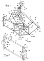
- FIG 1 illustrates an embodiment of the invention.
- a first element 1 is in the example conceived to be stationarily or rigidly mounted, e.g. to a stand secured to the floor and symbolised at 1. However, it is pointed out in this connection that the element 1 here described as "stationary” in itself may be movable in space by means of another movement equipment.
- a second element movable relative to the element 1 is denoted 2. This element has in the example the character of a frame.
- the element 2 is manipulatable in x-, y- and z-direction by means of force applying arrangements 3, 4 and 5.
- These are realised as drive means comprising a respective stationary portion a and a portion b movable relative thereto. It is preferred that the drive means 3, 4, 5 are shaped as rotation means, i.e. that their movable portions b are rotatable.
- These drive means 3, 4, 5 have their stationary portions a rigidly connected to the first element 1.
- At least three link arrangements A, B, C are coupled between the two elements 1, 2.
- the drive means 3, 4 and 5 are arranged to cause the link arrangements to move to thereby achieve a relative movement of the elements 1, 2.
- Each of the link arrangements A, B, C comprises at least one first component 6, 7, 8 and at least one second component 14, 15; 16, 17; 18, 19.
- the embodiment illustrated in Fig 1 will now initially be described, each link arrangement A, B, C in said embodiment comprising at least two parallel links, which can be said to form a forearm of each link arrangement.
- the first component 6, 7, 8 forms an upper arm of the respective link arrangement A, B, C.
- the second element 2 is built up as a frame to enable the hinged pairwise mounting in three dimension of the three pairs of parallel links 14, 15; 16, 17; 18, 19. It is decisive for the functioning of the robot with a SCARA-similar kinematics how the three pairs of links are mounted on the frame 2.
- the two links 14, 15; 16, 17; 18, 19 in each of the link arrangements A, B, C are hingedly connected to the upper arm component 6, 7 and 8 respectively of the link arrangements and to the frame 2. More specifically, the links 14 and 15 are, by means of joint arrangements 20, 21, connected to the arm component 6 whereas the links are connected to, by means of joint arrangements 22, 23, to the frame 2. These joint arrangements are designed so that they allow, in the assembled state of the robot, a relative movement with two and not more than two degrees of freedom between the forearm component formed by the links 14, 15 and the upper arm component 6 and the frame 2 respectively, said degrees of freedom consisting in pivotability in all directions about two real or imaginary axes placed at an angle to each other.
- the individual joints 20, 21, 22, 23 may be formed by cardan joints or ball joints.
- the forearm component of the link arrangement B comprises likewise two links 16, 17 arranged in parallel, said links being connected, via joints 24, 25, to the upper arm component 7 and, via joints 26, 27, to the frame 2.
- the forearm component is formed by the two parallel links 18, 19, which are connected, via joints 28, 29, to the upper arm component 8 and, via joints 30, 31, to the frame 2.
- the two links in each of the link pairs in the link arrangements A, B, C have substantially equal length, which means that they as a consequence of the parallelism form parallelograms.
- the drive means 3 has its movable portion b connected to the upper arm component 6 so that the latter is imparted pivotability about the axis denoted 37.
- the drive means 4 has its movable portion b connected to the upper arm component 7 of the link arrangement B so that the drive means 4 may impart the upper arm component 7 a pivoting movement. This pivoting movement occurs about the axis 37. It is pointed out that the two drive means 3 and 4 do not necessary have to have their axes of rotation parallel and even less coinciding as is illustrated in Fig 1 although this mostly is preferred, not the least since the kinematics then is simplified for turning around the robot with a large angle and more specifically up to a complete turn.
- the remaining C of the link arrangements has its upper arm component 8 pivotably arranged, more specifically about an axis denoted 38.
- This axis 38 is non-parallel to the pivoting axis 37 for at least one of the upper arm components 6, 7 belonging to the two other link arrangements A, B.
- the movable portion b of which comprises a gear wheel 9 contained in an angular gear 9/10.
- the conical gear wheel 10 is rigidly connected to the upper arm component 8 so that rotation of the gear wheel 10 gives rise to pivoting of the upper arm component 8 about the axis 38.
- the gear wheel 10 is rotatably supported in the upper arm component 7 of the link arrangement B by means of an axis 53.
- This arrangement means that on pivoting of the upper arm component 7 by means of the drive means 4 also the arm component 8 will accompany as a consequence of the fact that the axis 53 and also the gear wheel 10 will accompany the pivoting movement.
- the axis of rotation of the movable portion b of the drive means 5 coincides with the axis of rotation of b of the drive means 4.
- the mostly optimal embodiment in this regard is that the movable portions of all drive means 3, 4, 5 have their movable portions rotatable about one and the same geometrical axis 37.
- the lines 42 and 43 are parallel to the xy-plane whereas the line 44 is parallel to the z-axis. Furthermore, the line 43 forms the angle 45° with the line 42. At the same time, the directions of the lines 42, 43 and 44 define the orientation of the frame 2.
- the line 39 is defined by the joints 24 and 25 connecting the links 16 and 17 to the upper arm component 7 of the link arrangement B.
- the lines 39 and 42 must be mutually parallel.
- the line 41 is defined by the joints 20, 21 connecting the links 14 and 15 to the upper arm component 6. Pivoting centre lines 41 and 44 must, likewise, be mutually parallel.
- the line 40 in the link arrangement C is defined by the joints 28, 29 of the links 18, 19. The lines 40 and 43 must be mutually parallel.
- pivoting axis 37 for the drive means 3 belonging to the link arrangement A must be parallel to the lines 41 and 44.
- the pivoting axis 38 for the upper arm component 8 must be parallel to the lines 40 and 43.
- the pivoting axis 37 for the upper arm component 7 thereof i.e. the axis of rotation of the movable portion b of the drive means 4 of the link arrangement, is to be perpendicular to lines 39 and 42.
- the joints 18-31 may be of the type ball joint (spherical bearings) or cardan joint (Hooke-coupling).
- the use of ball joints is indicated in Fig 1. It is also possible to distribute the joint function of a pair of links according to Fig 2, where this arrangement is illustrated for the link pair 14, 15.
- a bearing 49 On the upper arm component 6 there is mounted a bearing 49, which enables the axle 46, which simultaneously functions as the stay 11 in Fig 1, to be rotated with its centre of rotation coinciding with the line 41.
- two bearings 47, 48 At the two ends of the axle 46 there are mounted two bearings 47, 48 so that the links 14, 15 may be pivoted upwardly/downwardly.
- the links are connected to the frame stay 32 via the bearings 50, 51 and 52.
- the bearing 52 provides the axle 45 with a centre of rotation coinciding with the line 44. It is pointed out that when the forearm component of the respective link arrangement is formed by two parallel links, the respective pivoting centre lines may be considered as being constituted of lines extending through such pivoting centra, which enable the links to pivot in their common plane.
- the links 14 and 15 should be equal in length and the distance between the joints 20 and 21 should be the same as the distance between the joints 22 and 23 (the distance between the joints is defined as the distance between the pivoting axes of the joints when the parallel links pivot in the plane formed by the links in unison).
- the links 16 and 17 should be equal in length and the distance between the joints 24 and 25 should be the same as the distance between the joints 26 and 27.
- the links 18 and 19 should be equal in length and the distance between the joints 28 and 29 should be equal to the distance between the joints 30 and 31.
- the upper arm component 7 comprises an angled portion 54, in which the axle 53 of the gear wheel 10 is journaled.
- the rotation centre axes for the drive means 4 and 5 must always coincide. On the contrary, it is not necessary that the rotation centre axis for the drive means 3 coincides with the common rotation centre axis for the drive means 4 and 5.
- the drive means 3, 4 and 5 will control the position of the frame 2 in x-, y- and z-direction.
- the robot may be used for e.g. picking and delivering objects with the working member 36 in the figure.
- the displacements of the working member will occur with a constant inclination ( ⁇ x and ⁇ y constant) whereas the orientation ( ⁇ z ) will depend on the direction of the arm component 7.
- it is, however, desired to be able to control the orientation of the object which means that a transmission for rotation of the working member 36 must be introduced, unless it is acceptable to increase the moving mass of the robot by placing a motor for ⁇ z -manipulation in the frame 2.
- the directions of the lines 42, 43 and 44 are decisive for the operation of the robot. If it is desired that the axis of rotation of the drive means 3 and 4 should be vertical so that the robot easily could be rotated around these axes as a SCARA robot, then the lines 41 and 44 must be vertical.
- the upper arm component 8 of the link arrangement C is movable relative to the upper arm component 7 of the link arrangement B and this in turn is pivotable relative to the first element 1, the upper arm component 8 will be movable relative to the first element 1 with two degrees of freedom, namely pivotability about two axes.
- pivot axes 37 and 38 for the upper arm components 7, 8 of the link arrangements B, C intersect each other.
- these pivot axes 37, 38 are perpendicular to each other.
- the line 44 has, in Fig 1, been placed on the frame part 32 and the line 42 on the frame part 33. However, this placement is arbitrary since the important thing is to have control over all degrees of freedom of the frame.
- the lines 44 and 42 may in principle be placed anywhere on an arbitrarily designed frame, as long as it is insured that the line 44 and the line 42 extend at an angle to each other.
- the joint pairs 22/23 and 26/27 may be placed anywhere on the lines 44 and 42 respectively.
- the line 43 there are great possibilities for variation.
- the line 43 may be displaced in parallel arbitrarily in the frame.
- the line 43 forms in the example a right angle to the line 44 whereas also the line 42 extends at a right angle relative to the line 44 and the line 43 forms an angle of substantially 45° relative to the line 42.
- these angle relations may be modified as indicated in Fig 3.
- the presentation given therein illustrates that the lines 43 and 42 may be changed, the line 44 being considered, in this case, as a starting point. It is indicated in Fig 3 with dashed lines that the lines 42 and 43 may be inclined considerably relative to the orientation illustrated in Fig 1. However, it is emphasised that the lines 42 and 43 may not be directed so that all lines 42, 43 and 44 would be present in the same plane.
- the lines 42, 43 and 44 may neither be parallel.
- the latter pivoting centre line 42 then forms an angle which preferably is in the range from -30 to +60° relative to planes perpendicular to the pivoting centre line 44.
- said angle of from -30 to +60° should be present as indicated in Fig 3 with respect to the line 42, namely only in one direction counted from the starting position as it appears from Fig 1.
- the pivoting centre line 43 for the joint arrangement 30, 31 forms angles which preferably are between -15 to +45° relative to planes perpendicular to the pivoting centre line 44 for the joint arrangement 22, 23 belonging to the link arrangement A.
- the orientation in the xy-plane of the frame i.e. its angle ⁇ z of rotation about the z-axis, is determined by the direction of the line 42 (in the xy-plane).
- the frame 2 in Fig 1 will be rotated when the arm component 7 is turned around.
- the arm component 7 may be replaced by a parallelogram, the extreme stay of which is connected to the arm part 12 and the inner stay of which is fixed to the stand 1.
- the drive means 4 is then arranged so that it puts the intermediate parallel stays in pivoting movement. Expressed in other words, this means that the arm component 7 in Fig 1 would be replaced by two parallel stays included in a parallelogram.
Landscapes
- Engineering & Computer Science (AREA)
- Robotics (AREA)
- Mechanical Engineering (AREA)
- Transmission Devices (AREA)
- Manipulator (AREA)
Claims (17)
- Einrichtung zur Relativbewegung zweier Elemente (1, 2), die mindestens drei Gliedanordnungen (A, B, C) umfasst, die zwischen den zwei Elementen (1, 2) eingefügt sind, sowie Kraft ausübende Anordnungen (3, 4, 5), um zu bewirken, dass sich die Gliedanordnungen (A, B, C) bewegen, um so für die Relativbewegung der Elemente (1, 2) zu sorgen, wobei jede der Gliedanordnungen mindestens eine erste Komponente (6, 7, 8) und mindestens eine zweite Komponente (14, 15, 16, 17, 18, 19) umfasst, wobei die ersten und zweiten Komponenten in jeder der Gliedanordnungen (A, B, C) verschwenkbar miteinander verbunden sind und zusätzlich mit einem jeweiligen zugeordneten der ersten und zweiten Elemente (1, 2) verschwenkbar verbunden sind, wobei die ersten und zweiten Komponenten in jeder der Gliedanordnungen (A, B, C) mittels Gelenkanordnungen (20, 21; 24, 25; 28, 29) miteinander verbunden sind, die zumindest in dem zusammengebauten Zustand der Einrichtung eine Relativbewegung mit zwei Freiheitsgraden zwischen den jeweiligen ersten und zweiten Komponenten ermöglichen, wobei die Freiheitsgrade in einer Verschwenkbarkeit um zwei reale oder imaginäre Achsen bestehen, die in einem Winkel zueinander angeordnet sind, wobei jede der mindestens einen zweiten Komponente durch Gelenkanordnungen (22, 23; 26, 27; 30, 31) mit dem zweiten Element (2) verbunden ist, die in dem zusammengebauten Zustand der Einrichtung eine relative Beweglichkeit zwischen den zweiten Komponenten und dem zweiten Element (2) mit zwei Freiheitsgraden in Form einer Schwenkbarkeit um zwei reale oder imaginäre Achsen ermöglichen, die in einem Winkel relativ zueinander angeordnet sind, wobei die mindestens eine zweite Komponente in jeder der Gliedanordnungen (A, B, C) mindestens zwei parallele Glieder umfasst, die jeweils durch Kardangelenke oder Kugelgelenke oder andere Gelenke, die ein Verschwenken um zwei oder drei in einem Winkel zueinander angeordnete Achsen ermöglichen, mit der ersten Komponente in der jeweiligen Gliedanordnung (A, B, C) und dem zweiten Element (2) verbunden sind, wobei die Gelenkanordnungen, die jede einzelne der zweiten Komponenten mit der ersten Komponente in der jeweiligen Gliedanordnung (A, B, C) und mit dem zweiten Element (2) verbinden, zueinander parallele reale oder imaginäre Schwenkachsen (42, 43, 44 und 39, 40, 41) bilden, wobei Linien (42, 43, 44), die sich durch Schwenkzentren erstrecken, die durch die Gelenkanordnungen zwischen der mindestens einen zweiten Komponente (14, 15, 16, 17, 18, 19) in den Gliedanordnungen (A, B, C) und dem zweiten Element (2) gebildet sind, nicht alle in der gleichen Ebene liegen, wobei für mindestens eine (A, C) der Gliedanordnungen deren erste Komponente (6, 8) relativ zu dem ersten Element (1) um eine Schwenkachse (37, 38) verschwenkbar ist, die im Wesentlichen parallel zu den Schwenkzentrumslinien (41, 44 bzw. 40, 43) zwischen der mindestens einen zweiten Komponente (14, 15; 18, 19) in der fraglichen Gliedanordnung und der ersten Komponente (6, 8) bzw. dem zweiten Element (2) verläuft, wobei die Schwenkzentrumslinien (42, 43, 44) für die Gliedanordnungen zwischen der mindestens einen zweiten Komponente in den Gliedanordnungen (A, B, C) und dem zweiten Element (2) nicht parallel verlaufen, wobei die erste Komponente (8) einer zweiten (C) der Gliedanordnungen um eine Achse (38) relativ zu dem ersten Element verschwenkbar ist und diese zuletzt erwähnte Achse (38) den gleichen Winkel in Bezug auf die Schwenkzentrumslinie (39) für die Gliedanordnung (24, 25) zwischen den ersten und zweiten Komponenten (7; 16, 17) einer weiteren Gliedanordnung (B) bildet, den die Schwenkzentrumslinie (43) zwischen der mindestens einen zweiten Komponente (18, 19) der zweiten Gliedanordnung (C) und dem zweiten Element (2) in Bezug auf die Schwenkzentrumslinie (42) zwischen der mindestens einen zweiten Komponente (16, 17) der weiteren Gliedanordnung (B) und dem zweiten Element (2) bildet,
dadurch gekennzeichnet, dass Ebenen, die sich parallel zu der Schwenkzentrumslinie (44) für die Gliedanordnung (22, 23) zwischen der mindestens einen zweiten Komponente (14, 15) und dem zweiten Element (2) von einer (A) ersten der Gliedanordnungen erstrecken und die sich außerdem parallel zu der Schwenkzentrumslinie (43) der Gelenkanordnung (30, 31) zwischen der mindestens einen zweiten Komponente (18, 19) und dem zweiten Element (2) der zweiten (C) der Gliedanordnungen erstrecken, einen Winkel bilden, der innerhalb 20 - 70°, vorzugsweise 30 - 60° und insbesondere bei etwa 45° in Bezug auf die Schwenkzentrumslinie (42) der Gelenkanordnung (26, 27) zwischen der mindestens einen zweiten Komponente (16, 17) und dem zweiten Element (2) der weiteren Gliedanordnung (B) liegt, und dadurch, dass die zuletzt erwähnte Schwenkzentrumslinie (42) einen Winkel, der vorzugsweise in dem Winkelbereich von -30 bis +60° liegt, in Bezug auf Ebenen bildet, die sich rechtwinklig zu der Schwenkzentrumslinie (44) für die Gliedanordnung (22, 23) zwischen der mindestens einen zweiten Komponente (14, 15) und dem zweiten Element (2) der ersten Gliedanordnung (A) erstrecken. - Einrichtung nach Anspruch 1, dadurch gekennzeichnet, dass die erste Komponente (8) der zweiten (C) der Gliedanordnungen angeordnet ist, um mit der ersten Komponente (7) der weiteren Gliedanordnung (B) verbunden zu sein, um bei einer Schwenkbewegung mit dieser ersten Komponente mitzugehen.
- Einrichtung nach Anspruch 2, dadurch gekennzeichnet, dass die erste Komponente (8) der zweiten (C) der Gliedanordnungen um eine Achse (38) relativ zu der ersten Komponente (7) der weiteren Gliedanordnung (B) verschwenkbar ist.
- Einrichtung nach Anspruch 1, dadurch gekennzeichnet, dass die erste Komponente (7) der weiteren Gliedanordnung (B) ein Parallelogramm umfasst.
- Einrichtung nach einem der vorhergehenden Ansprüche, dadurch gekennzeichnet, dass die ersten Komponenten (6, 7) von mindestens zwei (A, B) der Gliedanordnungen mit einem und nicht mehr als einem Freiheitsgrad relativ zu dem ersten Element (1) beweglich sind.
- Einrichtung nach einem der vorhergehenden Ansprüche, dadurch gekennzeichnet, dass die erste Komponente (8) mindestens einer (C) der Gliedanordnungen mit zwei und nicht mehr als zwei Freiheitsgraden relativ zu dem ersten Element (1) beweglich ist.
- Einrichtung nach einem der vorhergehenden Ansprüche, dadurch gekennzeichnet, dass sich die Schwenkachsen (37, 38) für die ersten Komponenten (7, 8) von zwei der Gliedanordnungen (B, C) gegenseitig schneiden.
- Einrichtung nach einem der vorhergehenden Ansprüche, dadurch gekennzeichnet, dass die Schwenkachsen (37, 38) für die ersten Komponenten (7, 8) von zwei der Gliedanordnungen (B, C) im Wesentlichen rechtwinklig zueinander verlaufen.
- Einrichtung nach einem der vorhergehenden Ansprüche, dadurch gekennzeichnet, dass die Kraft ausübende Anordnung (5) zum in Bewegung Bringen einer (C) der Gliedanordnungen einen ersten Abschnitt aufweist, der mit dem ersten Element (1) verbunden ist, während diese Kraft ausübende Anordnung einen zweiten Abschnitt aufweist, der relativ zu dem ersten erwähnten Abschnitt beweglich ist und der angeordnet ist, um zu bewirken, dass sich die erste Komponente (8) der ersten erwähnten (C) der Gliedanordnungen bewegt.
- Einrichtung nach einem der Ansprüche 1 bis 8, dadurch gekennzeichnet, dass die Kraft ausübende Anordnung (5) zum Bewirken, dass sich eine (C) der Gliedanordnungen bewegt, einen ersten Abschnitt, der starr mit dem ersten Element (1) verbunden ist, und einen zweiten Abschnitt aufweist, der relativ zu dem ersten beweglich ist und der angeordnet ist, um mittels eines Winkelgetriebes die erste Komponente einer weiteren (C) der Gliedanordnungen in eine Schwenkbewegung zu versetzen.
- Einrichtung nach einem der vorhergehenden Ansprüche, dadurch gekennzeichnet, dass die Schwenkachsen (37) für die ersten Komponenten (6, 7) von zwei (A, B) der Gliedanordnungen im Wesentlichen parallel verlaufen.
- Einrichtung nach Anspruch 11, dadurch gekennzeichnet, dass die Schwenkachsen (37) für die ersten Komponenten (6, 7) der zwei Gliedanordnungen (A, B) gegenseitig zusammenfallen.
- Einrichtung nach Anspruch 10, dadurch gekennzeichnet, dass die Drehachse der Kraft ausübenden Anordnung (5), die über das Winkelgetriebe (9, 10) auf die erste Komponente (8) einer (C) der Gliedanordnungen einwirkt, im Wesentlichen parallel und vorzugsweise im Wesentlichen zusammenfallend mit der Drehachse einer anderen (4) Kraft ausübenden Anordnung verläuft, die einen ersten Abschnitt, der starr mit dem ersten Element (1) verbunden ist, und einen zweiten Abschnitt aufweist, der relativ zu dem ersten Abschnitt beweglich ist und mit der ersten Komponente (7) einer anderen (B) der Gliedanordnungen verbunden ist, genauer gesagt der Gliedanordnung, mit deren Bewegung die erste Komponente (8) der ersten erwähnten Gliedanordnung (C) angeordnet ist, mitzugehen.
- Einrichtung nach einem der vorhergehenden Ansprüche, dadurch gekennzeichnet, dass für mindestens eine der Gliedanordnungen (A, B, C) die zweiten Komponenten (14, 15; 16, 17; 18, 19) durch mindestens zwei im Wesentlichen parallele Glieder gebildet sind.
- Einrichtung nach Anspruch 11, dadurch gekennzeichnet, dass jedes einzelne Gelenk (20, 21; 22, 23; 26, 27; 24, 25; 28, 29; 30, 31) der parallelen Glieder für sich selbst betrachtet zwei oder drei Freiheitsgrade umfasst.
- Einrichtung nach einem der vorhergehenden Ansprüche, dadurch gekennzeichnet, dass die Schwenkzentrumslinie (43) der Gelenkanordnung (30, 31) zwischen der mindestens einen zweiten Komponente (18, 19) und dem zweiten Element (2) der zweiten Gliedanordnung (C) Winkel bildet, die vorzugsweise zwischen -15 und +45° in Bezug auf Ebenen liegen, die sich rechtwinklig zu der Schwenkzentrumslinie (44) der Gelenkanordnung (22, 23) zwischen der mindestens einen zweiten Komponente (14, 15) und dem zweiten Element (2) der ersten Gliedanordnung erstrecken.
- Einrichtung nach einem der vorhergehenden Ansprüche, dadurch gekennzeichnet, dass sie durch einen Industrieroboter ausgeführt ist, dessen zweites Element (2) dafür eingerichtet ist, direkt oder indirekt mindestens ein Arbeitselement (3) zu tragen.
Applications Claiming Priority (3)
| Application Number | Priority Date | Filing Date | Title |
|---|---|---|---|
| SE9801518A SE512931C2 (sv) | 1998-04-29 | 1998-04-29 | Anordning för relativ förflyttning av två element |
| SE9801518 | 1998-04-29 | ||
| PCT/SE1999/000705 WO1999058301A1 (en) | 1998-04-29 | 1999-04-29 | A device for relative movement of two elements |
Publications (2)
| Publication Number | Publication Date |
|---|---|
| EP1075360A1 EP1075360A1 (de) | 2001-02-14 |
| EP1075360B1 true EP1075360B1 (de) | 2007-01-17 |
Family
ID=20411146
Family Applications (1)
| Application Number | Title | Priority Date | Filing Date |
|---|---|---|---|
| EP99950331A Expired - Lifetime EP1075360B1 (de) | 1998-04-29 | 1999-04-29 | Vorrichtung zur relativen bewegung von zwei teilen |
Country Status (8)
| Country | Link |
|---|---|
| US (1) | US6412363B1 (de) |
| EP (1) | EP1075360B1 (de) |
| JP (1) | JP4070956B2 (de) |
| KR (1) | KR20010024978A (de) |
| CA (1) | CA2329990A1 (de) |
| DE (1) | DE69934880T2 (de) |
| SE (1) | SE512931C2 (de) |
| WO (1) | WO1999058301A1 (de) |
Families Citing this family (21)
| Publication number | Priority date | Publication date | Assignee | Title |
|---|---|---|---|---|
| US7337691B2 (en) * | 1999-08-05 | 2008-03-04 | Shambhu Nath Roy | Parallel kinematics mechanism with a concentric spherical joint |
| SE517356C2 (sv) * | 2000-09-11 | 2002-05-28 | Abb Ab | Manipulator innefattande minst tre armar för förflyttning av en kropp i rymden |
| SE0100134D0 (sv) | 2001-01-15 | 2001-01-15 | Abb Ab | Industrirobot |
| JP4628602B2 (ja) * | 2001-04-05 | 2011-02-09 | ナブテスコ株式会社 | ロボットアーム |
| US7637710B2 (en) | 2002-01-16 | 2009-12-29 | Abb Ab | Industrial robot |
| SE524747C2 (sv) | 2002-02-06 | 2004-09-28 | Abb Ab | Industrirobot innehållande en parallellkinematisk manipulator för förflyttning av ett föremål i rymden |
| CA2505108A1 (en) * | 2002-11-06 | 2004-05-21 | Mcgill University | Four-degree-of-freedom parallel manipulator for producing schonflies motions |
| KR101083734B1 (ko) * | 2004-02-17 | 2011-11-16 | 한국항공우주산업 주식회사 | 항공기 구조물 변형 테스트 장치 |
| KR100839361B1 (ko) * | 2006-10-23 | 2008-06-19 | 삼성중공업 주식회사 | 파이프 자동 정렬 장치의 병렬로봇 설계 방법 |
| US20120073738A1 (en) | 2010-09-29 | 2012-03-29 | The Boeing Company | Method and apparatus for laying up barrel-shaped composite structures |
| JP2012192499A (ja) * | 2011-03-17 | 2012-10-11 | Canon Electronics Inc | パラレルリンクロボット |
| JP5602676B2 (ja) * | 2011-05-20 | 2014-10-08 | Ckd株式会社 | 可動体支持装置 |
| WO2013070938A1 (en) * | 2011-11-08 | 2013-05-16 | Ross-Hime Designs, Incorporated | Robotic manipulator with spherical joints |
| JP5889767B2 (ja) * | 2012-10-16 | 2016-03-22 | Ckd株式会社 | 工具保持装置 |
| US9048779B2 (en) * | 2013-04-19 | 2015-06-02 | Randall Lee Szarzynski | Multi-dimensional positioning of an object |
| EP2999572B1 (de) * | 2013-05-23 | 2018-04-18 | ABB Schweiz AG | Kompakter parallelkinematikroboter |
| KR101627766B1 (ko) * | 2014-02-04 | 2016-06-07 | 전남대학교산학협력단 | 케이블 기반 병렬형 로봇을 위한 케이블 연결 위치 변경장치 |
| DE102015003239A1 (de) * | 2015-03-10 | 2016-09-15 | Beumer Gmbh & Co. Kg | Vorrichtung zum Be- oder Entladen einen Transportbehälters |
| CN106695766B (zh) * | 2017-03-01 | 2023-04-28 | 东莞松山湖机器人产业发展有限公司 | 一种基于抓取并联机构的六自由度并联装置 |
| EP3611420A1 (de) * | 2018-08-16 | 2020-02-19 | Ondal Medical Systems GmbH | Vorrichtung zum tragen eines monitors |
| EP4296160A4 (de) * | 2021-02-17 | 2025-03-12 | Mochizuki, Leona | Drehmechanismus, fluggerät sowie vorrichtung und verfahren zur steuerung der lage einer last |
Family Cites Families (8)
| Publication number | Priority date | Publication date | Assignee | Title |
|---|---|---|---|---|
| CH617559GA3 (de) * | 1977-12-29 | 1980-06-13 | ||
| JPS5656396A (en) * | 1979-10-12 | 1981-05-18 | Hiroshi Makino | Robot for assembly |
| JPS5856789A (ja) * | 1981-09-25 | 1983-04-04 | 松下電器産業株式会社 | ハンドリング装置 |
| CH672089A5 (de) | 1985-12-16 | 1989-10-31 | Sogeva Sa | |
| SU1472252A1 (ru) * | 1987-08-20 | 1989-04-15 | Азербайджанский политехнический институт им.Ч.Ильдрыма | Манипул тор |
| SU1691092A1 (ru) * | 1989-10-24 | 1991-11-15 | Одесское специальное конструкторское бюро прецизионных станков | Обрабатывающее устройство |
| US5156062A (en) | 1991-07-01 | 1992-10-20 | Rockwell International Corporation | Anti-rotation positioning mechanism |
| FR2688437B1 (fr) * | 1992-03-11 | 1994-06-10 | Centre Nat Rech Scient | Manipulateur spatial parallele a six degres de liberte. |
-
1998
- 1998-04-29 SE SE9801518A patent/SE512931C2/sv not_active IP Right Cessation
-
1999
- 1999-04-29 DE DE69934880T patent/DE69934880T2/de not_active Expired - Lifetime
- 1999-04-29 WO PCT/SE1999/000705 patent/WO1999058301A1/en not_active Ceased
- 1999-04-29 JP JP2000548130A patent/JP4070956B2/ja not_active Expired - Lifetime
- 1999-04-29 KR KR1020007011936A patent/KR20010024978A/ko not_active Abandoned
- 1999-04-29 CA CA002329990A patent/CA2329990A1/en not_active Abandoned
- 1999-04-29 US US09/674,151 patent/US6412363B1/en not_active Expired - Lifetime
- 1999-04-29 EP EP99950331A patent/EP1075360B1/de not_active Expired - Lifetime
Also Published As
| Publication number | Publication date |
|---|---|
| EP1075360A1 (de) | 2001-02-14 |
| US6412363B1 (en) | 2002-07-02 |
| KR20010024978A (ko) | 2001-03-26 |
| SE9801518L (sv) | 1999-10-30 |
| JP4070956B2 (ja) | 2008-04-02 |
| SE512931C2 (sv) | 2000-06-05 |
| DE69934880T2 (de) | 2007-05-31 |
| WO1999058301A1 (en) | 1999-11-18 |
| JP2002514519A (ja) | 2002-05-21 |
| SE9801518D0 (sv) | 1998-04-29 |
| DE69934880D1 (de) | 2007-03-08 |
| CA2329990A1 (en) | 1999-11-18 |
Similar Documents
| Publication | Publication Date | Title |
|---|---|---|
| US6412363B1 (en) | Device for relative movement of two elements | |
| US11865711B2 (en) | Industrial robot arm | |
| Tsai | Kinematics of a three-DOF platform with three extensible limbs | |
| US7011489B2 (en) | Industrial robot | |
| EP1870214B1 (de) | Hochgeschwindigkeitsparallelroboter mit vier freiheitsgraden | |
| US7637710B2 (en) | Industrial robot | |
| US7337691B2 (en) | Parallel kinematics mechanism with a concentric spherical joint | |
| US20040123694A1 (en) | Modular and reconfigurable parallel kinematic robot | |
| EP0894038B1 (de) | Einrichtung zur relativbewegung von zwei elementen | |
| JPS63150178A (ja) | マニピュレータ | |
| CA2505108A1 (en) | Four-degree-of-freedom parallel manipulator for producing schonflies motions | |
| US7392722B2 (en) | Control unit with three parallel branches | |
| US6336374B1 (en) | Device for relative displacement of two elements | |
| Parenti-Castelli et al. | Workspace and optimal design of a pure translation parallel manipulator | |
| US20040013509A1 (en) | Parallel kinematics mechanism with a concentric spherical joint | |
| Fang et al. | Analytical identification of limb structures for translational parallel manipulators | |
| Liu et al. | Parallel mechanisms with two or three degrees of freedom |
Legal Events
| Date | Code | Title | Description |
|---|---|---|---|
| PUAI | Public reference made under article 153(3) epc to a published international application that has entered the european phase |
Free format text: ORIGINAL CODE: 0009012 |
|
| 17P | Request for examination filed |
Effective date: 20001024 |
|
| AK | Designated contracting states |
Kind code of ref document: A1 Designated state(s): BE CH DE ES FI FR GB IT LI NL SE |
|
| 17Q | First examination report despatched |
Effective date: 20010510 |
|
| GRAP | Despatch of communication of intention to grant a patent |
Free format text: ORIGINAL CODE: EPIDOSNIGR1 |
|
| GRAS | Grant fee paid |
Free format text: ORIGINAL CODE: EPIDOSNIGR3 |
|
| GRAA | (expected) grant |
Free format text: ORIGINAL CODE: 0009210 |
|
| AK | Designated contracting states |
Kind code of ref document: B1 Designated state(s): BE CH DE ES FI FR GB IT LI NL SE |
|
| PG25 | Lapsed in a contracting state [announced via postgrant information from national office to epo] |
Ref country code: NL Free format text: LAPSE BECAUSE OF FAILURE TO SUBMIT A TRANSLATION OF THE DESCRIPTION OR TO PAY THE FEE WITHIN THE PRESCRIBED TIME-LIMIT Effective date: 20070117 Ref country code: LI Free format text: LAPSE BECAUSE OF FAILURE TO SUBMIT A TRANSLATION OF THE DESCRIPTION OR TO PAY THE FEE WITHIN THE PRESCRIBED TIME-LIMIT Effective date: 20070117 Ref country code: FI Free format text: LAPSE BECAUSE OF FAILURE TO SUBMIT A TRANSLATION OF THE DESCRIPTION OR TO PAY THE FEE WITHIN THE PRESCRIBED TIME-LIMIT Effective date: 20070117 Ref country code: CH Free format text: LAPSE BECAUSE OF FAILURE TO SUBMIT A TRANSLATION OF THE DESCRIPTION OR TO PAY THE FEE WITHIN THE PRESCRIBED TIME-LIMIT Effective date: 20070117 |
|
| REG | Reference to a national code |
Ref country code: GB Ref legal event code: FG4D |
|
| REG | Reference to a national code |
Ref country code: CH Ref legal event code: EP |
|
| REF | Corresponds to: |
Ref document number: 69934880 Country of ref document: DE Date of ref document: 20070308 Kind code of ref document: P |
|
| PG25 | Lapsed in a contracting state [announced via postgrant information from national office to epo] |
Ref country code: SE Free format text: LAPSE BECAUSE OF FAILURE TO SUBMIT A TRANSLATION OF THE DESCRIPTION OR TO PAY THE FEE WITHIN THE PRESCRIBED TIME-LIMIT Effective date: 20070417 |
|
| PG25 | Lapsed in a contracting state [announced via postgrant information from national office to epo] |
Ref country code: ES Free format text: LAPSE BECAUSE OF FAILURE TO SUBMIT A TRANSLATION OF THE DESCRIPTION OR TO PAY THE FEE WITHIN THE PRESCRIBED TIME-LIMIT Effective date: 20070428 |
|
| NLV1 | Nl: lapsed or annulled due to failure to fulfill the requirements of art. 29p and 29m of the patents act | ||
| REG | Reference to a national code |
Ref country code: CH Ref legal event code: PL |
|
| PLBE | No opposition filed within time limit |
Free format text: ORIGINAL CODE: 0009261 |
|
| STAA | Information on the status of an ep patent application or granted ep patent |
Free format text: STATUS: NO OPPOSITION FILED WITHIN TIME LIMIT |
|
| 26N | No opposition filed |
Effective date: 20071018 |
|
| GBPC | Gb: european patent ceased through non-payment of renewal fee |
Effective date: 20070429 |
|
| PG25 | Lapsed in a contracting state [announced via postgrant information from national office to epo] |
Ref country code: BE Free format text: LAPSE BECAUSE OF FAILURE TO SUBMIT A TRANSLATION OF THE DESCRIPTION OR TO PAY THE FEE WITHIN THE PRESCRIBED TIME-LIMIT Effective date: 20070117 |
|
| PG25 | Lapsed in a contracting state [announced via postgrant information from national office to epo] |
Ref country code: GB Free format text: LAPSE BECAUSE OF NON-PAYMENT OF DUE FEES Effective date: 20070429 Ref country code: FR Free format text: LAPSE BECAUSE OF FAILURE TO SUBMIT A TRANSLATION OF THE DESCRIPTION OR TO PAY THE FEE WITHIN THE PRESCRIBED TIME-LIMIT Effective date: 20070907 |
|
| PG25 | Lapsed in a contracting state [announced via postgrant information from national office to epo] |
Ref country code: FR Free format text: LAPSE BECAUSE OF FAILURE TO SUBMIT A TRANSLATION OF THE DESCRIPTION OR TO PAY THE FEE WITHIN THE PRESCRIBED TIME-LIMIT Effective date: 20070117 |
|
| PGFP | Annual fee paid to national office [announced via postgrant information from national office to epo] |
Ref country code: IT Payment date: 20120423 Year of fee payment: 14 |
|
| PG25 | Lapsed in a contracting state [announced via postgrant information from national office to epo] |
Ref country code: IT Free format text: LAPSE BECAUSE OF NON-PAYMENT OF DUE FEES Effective date: 20130429 |
|
| REG | Reference to a national code |
Ref country code: DE Ref legal event code: R082 Ref document number: 69934880 Country of ref document: DE Representative=s name: BECKER, KURIG, STRAUS, DE Ref country code: DE Ref legal event code: R081 Ref document number: 69934880 Country of ref document: DE Owner name: ABB SCHWEIZ AG, CH Free format text: FORMER OWNER: ABB AB, VAESTERAS, SE |
|
| PGFP | Annual fee paid to national office [announced via postgrant information from national office to epo] |
Ref country code: DE Payment date: 20180420 Year of fee payment: 20 |
|
| REG | Reference to a national code |
Ref country code: DE Ref legal event code: R071 Ref document number: 69934880 Country of ref document: DE |