EP1075366B1 - Machine a bois - Google Patents
Machine a bois Download PDFInfo
- Publication number
- EP1075366B1 EP1075366B1 EP99913796A EP99913796A EP1075366B1 EP 1075366 B1 EP1075366 B1 EP 1075366B1 EP 99913796 A EP99913796 A EP 99913796A EP 99913796 A EP99913796 A EP 99913796A EP 1075366 B1 EP1075366 B1 EP 1075366B1
- Authority
- EP
- European Patent Office
- Prior art keywords
- wood
- trough
- rotors
- feeding
- machine
- Prior art date
- Legal status (The legal status is an assumption and is not a legal conclusion. Google has not performed a legal analysis and makes no representation as to the accuracy of the status listed.)
- Expired - Lifetime
Links
- 239000002023 wood Substances 0.000 title claims abstract description 48
- 239000000428 dust Substances 0.000 claims description 2
- 239000000835 fiber Substances 0.000 description 2
- 239000000725 suspension Substances 0.000 description 1
Images

Classifications
-
- B—PERFORMING OPERATIONS; TRANSPORTING
- B27—WORKING OR PRESERVING WOOD OR SIMILAR MATERIAL; NAILING OR STAPLING MACHINES IN GENERAL
- B27L—REMOVING BARK OR VESTIGES OF BRANCHES; SPLITTING WOOD; MANUFACTURE OF VENEER, WOODEN STICKS, WOOD SHAVINGS, WOOD FIBRES OR WOOD POWDER
- B27L1/00—Debarking or removing vestiges of branches from trees or logs; Machines therefor
- B27L1/02—Debarking or removing vestiges of branches from trees or logs; Machines therefor by rubbing the trunks against each other; Equipment for wet practice
-
- B—PERFORMING OPERATIONS; TRANSPORTING
- B27—WORKING OR PRESERVING WOOD OR SIMILAR MATERIAL; NAILING OR STAPLING MACHINES IN GENERAL
- B27L—REMOVING BARK OR VESTIGES OF BRANCHES; SPLITTING WOOD; MANUFACTURE OF VENEER, WOODEN STICKS, WOOD SHAVINGS, WOOD FIBRES OR WOOD POWDER
- B27L1/00—Debarking or removing vestiges of branches from trees or logs; Machines therefor
- B27L1/10—Debarking or removing vestiges of branches from trees or logs; Machines therefor using rotatable tools
Definitions
- This invention relates to a machine for working wood like pulp wood, sawtimber or similar elongated wood parts according to the preamble portion of claim 1.
- Such a machine is known for example from SE-A-144,422.
- Machines are previously known which have been designed with longitudinal rotors with strong heels, intended to work the bark of the wood. In order that the machine shall function satisfactory, it has been designed in that way that the feeding in end of the trough has been placed essentially higher than its feeding out end. Due to that fact, the transport of the wood through the machine has been made on a downward slope. This fact regarding the position of the trough means partly that the wood has to be lifted to a high position at the feeding in end, partly to be lifted up a good distance at the feeding out end in order to be able to be smoothly fed into a following chipper, saw station or the like.
- the purpose with the present invention is to bring about an adjustable, lenient working of the wood, which makes the treatment of wood, which is hard to work as well as easy to work possible.
- the transport through the trough from its feeding in end to its feeding out end is preferably made on an upward slope, i.e. a longitudinal centre line through the trough from the feeding in end to its feeding out end inclines upwards. Due to that fact, the feeding of the wood into the trough is made on a low level and the feeding out to a following working station, for instance a chipper, is made an a relatively high level.
- FIG. 1a shows the wood working machine from the side
- Fig. 1b shows the machine from above
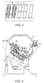
- Fig. 2 shows a part of a longitudinal section, taken in parallel with the upperside of the rotors
- Fig. 3 shows a section through the machine, taken along the line III-III in fig. 1b.
- the wood working machine which has a trough 2 in the form of a tunnel which is articulately suspended in a frame 1, the trough having a feeding in end 3, and a feeding out end 4 for the wood.
- a feeding in opening 5 for the wood At the feeding in end 3 there is a feeding in opening 5 for the wood.
- the trough 2 has a great number of helical rotors 6 (see figs. 2, 3) at its lower part 7 and is provided with an openable cover 8 at its upper part in front of the feeding in opening 5 for reduction of dust and noise. Over the feeding in opening 5 itself there is no cover, whether fixed or openable. Due to that fact, the feeding of wood into the trough is facilitated.
- a side portion of the trough has a suitably designed wall 9.
- the helical rotors 6, the one end of which is connected to the lower portion 10 of the wall 9 is provided with means and are inclined upwards in the direction from the lower portion 10 of the wall 9.
- This inclination of the helical rotors 6 are steplessly adjustable by the fact that the trough 2 can be steplessly pivoted about a suspension point 11, which can be a shaft, that is parallel with the longitudinal direction of the trough, by means of for instance a piston cylinder 12 or a screw jack.
- a suspension point 11 can be a shaft, that is parallel with the longitudinal direction of the trough, by means of for instance a piston cylinder 12 or a screw jack.
- This means that the trough 2 can take different angle positions in relation to a transverse, horizontal line, drawn through the machine.
- the helical rotors 6 are provided with screw threads 13 on its outer surface. This fact plus the fact that the rotors are obliquely positioned in relation to a transverse line through the machine make possible that the wood falls down between the threads and are given a movement from below and upwards (see fig. 3) at the same time as a debarking of the wood is made. At least certain parts of the screw threads are provided with flails 14 or similar means, which are intended to damage the bark, whereby the debarking is made more effective.
- the helical rotors 6 are driven by one or more electric motors and have a length of about 2 m.
- the rotors 6 have a diameter of 600 mm and a pitch of about 800 mm.
- the rotors 6 are further arranged with an initial inclination so that they by means of the lifting cylinder can take an angle position in relation to the transverse horizontal line between 25° and 45°.
- a conveyer 15 For collection of bark and wastage is a conveyer 15 arranged under the wood working machine.
- the wood working machine functions in that way that when wood in bundles or continuously is laid down into the trough 2 of the machine, it is influenced by the threads 13 of the helical rotors 6 so that it is lifted up and begins to rotate (tumble) in the trough 2 at the same time as it is driven upwards. Due to that fact, worked wood from its uppermost position will fall back to the bottom portion of the trough and once again begin to be worked. During the rotation of the rotors 6, the wood will not only be lifted upwards but of course be brought forwards towards the feeding out end 4 of the trough.
Landscapes
- Life Sciences & Earth Sciences (AREA)
- Engineering & Computer Science (AREA)
- Wood Science & Technology (AREA)
- Forests & Forestry (AREA)
- Jigging Conveyors (AREA)
- Debarking, Splitting, And Disintegration Of Timber (AREA)
- Paper (AREA)
- Dry Formation Of Fiberboard And The Like (AREA)
- Fish Paste Products (AREA)
- Chemical And Physical Treatments For Wood And The Like (AREA)
- Bakery Products And Manufacturing Methods Therefor (AREA)
- Soil Working Implements (AREA)
- Formation And Processing Of Food Products (AREA)
- Table Devices Or Equipment (AREA)
Claims (2)
- Machine de traitement de bois tel que du bois à pâte, du bois de sciage ou des pièces de bois allongées similaires, la machine comprenant une auge qui présente une extrémité d'amenée et une extrémité de décharge du bois, et dans laquelle sont agencés une pluralité de rotors munis de moyens d'écorçage sur chaque surface extérieure de rotor pour un écorçage au moins partiel du bois,
les rotors (6) étant disposés de telle manière que leur direction longitudinale forme un angle avec une ligne horizontale transversale à travers la machine, et munis de filets hélicoïdaux sur leurs enveloppes, caractérisée par les particularités suivantes:l'auge (2) est conçue en forme de tunnel et de telle manière que le bois est amené à ladite auge à un premier bas niveau, alors que le bois est déchargé de l'auge (2) à un deuxième niveau plus élevé, c'est-à-dire que la ligne médiane longitudinale de l'auge est inclinée vers le haut à partir de l'extrémité d'amenée;les rotors (6) sont agencés de telle manière que l'angle entre l'axe longitudinal des rotors et la direction longitudinale de l'auge est inférieur à 90°, c'est-à-dire que. l'axe des rotors est incliné vers l'arrière dans la direction de transport;l'auge (2) est conçue de manière à pouvoir pivoter en continu autour d'un arbre (11) qui est parallèle à la direction longitudinale de l'auge, ce qui signifie que l'auge peut prendre des positions angulaires différentes par rapport à une ligne horizontale transversale à travers la machine, et ce qui signifie également que l'angle entre la direction longitudinale des rotors (6) et la ligne horizontale transversale à travers la machine peut être varié en continu. - Machine selon la revendication 1, caractérisée en ce que l'auge (2) est pourvue dans sa partie supérieure d'un couvercle (8) pouvant être ouvert pour réduire la poussière et le bruit.
Applications Claiming Priority (3)
| Application Number | Priority Date | Filing Date | Title |
|---|---|---|---|
| SE9800926 | 1998-03-20 | ||
| SE9800926A SE9800926D0 (sv) | 1998-03-20 | 1998-03-20 | Vedbearbetningsmaskin |
| PCT/SE1999/000412 WO1999048657A1 (fr) | 1998-03-20 | 1999-03-17 | Machine a bois |
Publications (2)
| Publication Number | Publication Date |
|---|---|
| EP1075366A1 EP1075366A1 (fr) | 2001-02-14 |
| EP1075366B1 true EP1075366B1 (fr) | 2004-10-13 |
Family
ID=20410619
Family Applications (1)
| Application Number | Title | Priority Date | Filing Date |
|---|---|---|---|
| EP99913796A Expired - Lifetime EP1075366B1 (fr) | 1998-03-20 | 1999-03-17 | Machine a bois |
Country Status (8)
| Country | Link |
|---|---|
| US (1) | US6360796B1 (fr) |
| EP (1) | EP1075366B1 (fr) |
| AT (1) | ATE279309T1 (fr) |
| AU (1) | AU3178799A (fr) |
| CA (1) | CA2324579A1 (fr) |
| DE (1) | DE69921113T2 (fr) |
| SE (1) | SE9800926D0 (fr) |
| WO (1) | WO1999048657A1 (fr) |
Cited By (1)
| Publication number | Priority date | Publication date | Assignee | Title |
|---|---|---|---|---|
| CN103358375A (zh) * | 2013-07-12 | 2013-10-23 | 海南金海浆纸业有限公司 | 一种制浆造纸原木剥皮机 |
Families Citing this family (7)
| Publication number | Priority date | Publication date | Assignee | Title |
|---|---|---|---|---|
| US6619346B2 (en) * | 2001-04-13 | 2003-09-16 | Andritz Oy | Debarking machine |
| DE202009016936U1 (de) | 2009-12-15 | 2010-04-15 | Rudnick & Enners Maschinen- Und Anlagenbau Gmbh | Entrindungswelle für einen Entrindungsprozess mit einer lösbaren Befestigung der Entrindungswerkzeuge |
| CN103144171A (zh) * | 2013-03-17 | 2013-06-12 | 福建鑫华股份有限公司 | 构树皮剥取装置 |
| CN103144172A (zh) * | 2013-03-17 | 2013-06-12 | 福建鑫华股份有限公司 | 构树皮剥取的方法 |
| US20170087740A1 (en) * | 2015-09-30 | 2017-03-30 | Les Aciers J.P. Inc. | Rotary log debarker with tilting system |
| CN112405756B (zh) * | 2020-11-19 | 2022-01-21 | 日照益尔居木业股份有限公司 | 一种木材加工用木材剥皮机 |
| CN112454572A (zh) * | 2020-11-19 | 2021-03-09 | 太湖县华鑫工艺品有限公司 | 一种藤制品原材料去皮装置 |
Family Cites Families (11)
| Publication number | Priority date | Publication date | Assignee | Title |
|---|---|---|---|---|
| SE89542C1 (fr) * | 1935-02-15 | 1937-06-22 | ||
| SE144422C1 (fr) * | 1947-03-20 | 1954-03-09 | ||
| FI56135C (fi) | 1976-10-11 | 1979-12-10 | Kone Oy | Anordning foer avbarkning av virke |
| US4685498A (en) | 1984-02-08 | 1987-08-11 | Fuji Kogyo K.K. | Barking machine |
| JPS62151301A (ja) * | 1985-12-25 | 1987-07-06 | 富士鋼業株式会社 | 皮剥機 |
| FI83181C (fi) * | 1989-07-03 | 1991-06-10 | Rauma Repola Oy | Foerfarande och transportoer foer transport av fast material i stycken eller partiklar. |
| JPH0929712A (ja) * | 1995-07-21 | 1997-02-04 | Fuji Kogyo Kk | 皮剥装置の皮剥歯 |
| US5630453A (en) * | 1996-05-24 | 1997-05-20 | Fuji Kogyo Co., Ltd. | Debarking machine |
| CA2186098C (fr) * | 1996-09-20 | 1999-04-20 | Eric Gagne | Ecorceuse a cylindres multiples |
| FI101524B (fi) * | 1996-12-10 | 1998-07-15 | Andritz Patentverwaltung | Laite kuorien poistamiseksi puuta ja kuorta sisältävästä puuvirrasta |
| FI103491B2 (fi) * | 1997-06-25 | 2005-05-18 | Sunds Defibrator Woodhandling | Menetelmä ja laitteisto kuorittavan puun käsittelemiseksi |
-
1998
- 1998-03-20 SE SE9800926A patent/SE9800926D0/xx unknown
-
1999
- 1999-03-17 DE DE69921113T patent/DE69921113T2/de not_active Expired - Fee Related
- 1999-03-17 WO PCT/SE1999/000412 patent/WO1999048657A1/fr not_active Ceased
- 1999-03-17 CA CA002324579A patent/CA2324579A1/fr not_active Abandoned
- 1999-03-17 AT AT99913796T patent/ATE279309T1/de not_active IP Right Cessation
- 1999-03-17 US US09/646,658 patent/US6360796B1/en not_active Expired - Fee Related
- 1999-03-17 AU AU31787/99A patent/AU3178799A/en not_active Abandoned
- 1999-03-17 EP EP99913796A patent/EP1075366B1/fr not_active Expired - Lifetime
Cited By (1)
| Publication number | Priority date | Publication date | Assignee | Title |
|---|---|---|---|---|
| CN103358375A (zh) * | 2013-07-12 | 2013-10-23 | 海南金海浆纸业有限公司 | 一种制浆造纸原木剥皮机 |
Also Published As
| Publication number | Publication date |
|---|---|
| DE69921113T2 (de) | 2005-10-27 |
| ATE279309T1 (de) | 2004-10-15 |
| AU3178799A (en) | 1999-10-18 |
| DE69921113D1 (de) | 2004-11-18 |
| CA2324579A1 (fr) | 1999-09-30 |
| EP1075366A1 (fr) | 2001-02-14 |
| US6360796B1 (en) | 2002-03-26 |
| WO1999048657A1 (fr) | 1999-09-30 |
| SE9800926D0 (sv) | 1998-03-20 |
Similar Documents
| Publication | Publication Date | Title |
|---|---|---|
| EP0808699B1 (fr) | Machine d'écorçage | |
| US4685498A (en) | Barking machine | |
| EP2142302B1 (fr) | Déchiqueteuse de rémanents avec rouleaux alimenteurs améliorés | |
| EP1075366B1 (fr) | Machine a bois | |
| US4214616A (en) | Tree delimbing apparatus | |
| CN109250466A (zh) | 码垛装置 | |
| FI80227B (fi) | Anordning foer matande av traed i en barkningstrumma. | |
| US5349999A (en) | Mobile combination debarking/chipping machine | |
| USRE37460E1 (en) | Method and apparatus for debarking logs | |
| US4711280A (en) | Vertical flail delimber | |
| NO127227B (fr) | ||
| CN109203090A (zh) | 中药材种植原木供料装置 | |
| CA1097583A (fr) | Traduction non-disponible | |
| US4344470A (en) | Delimbing apparatus | |
| US3215176A (en) | Log debarking apparatus | |
| US3016074A (en) | Log debarking machines | |
| US6941988B2 (en) | Batch rotary debarker | |
| SE459565B (sv) | Anordning foer trumbarkning | |
| FI103491B (fi) | Menetelmä ja laitteisto kuorittavan puun käsittelemiseksi | |
| US20080185073A1 (en) | Processing apparatus of wood to be chipped | |
| CN224041715U (zh) | 树皮短木分选设备 | |
| NO161196B (no) | Testremse for paavisning av ikke synlig blod. | |
| GB1560137A (en) | Means for extracting silage from the top of a silo | |
| CN109129721A (zh) | 中药材种植原木分料导送装置 | |
| CN108967051A (zh) | 药材种植木段用刨皮装置 |
Legal Events
| Date | Code | Title | Description |
|---|---|---|---|
| PUAI | Public reference made under article 153(3) epc to a published international application that has entered the european phase |
Free format text: ORIGINAL CODE: 0009012 |
|
| 17P | Request for examination filed |
Effective date: 20000911 |
|
| AK | Designated contracting states |
Kind code of ref document: A1 Designated state(s): AT DE ES FI FR PT SE |
|
| GRAP | Despatch of communication of intention to grant a patent |
Free format text: ORIGINAL CODE: EPIDOSNIGR1 |
|
| GRAS | Grant fee paid |
Free format text: ORIGINAL CODE: EPIDOSNIGR3 |
|
| GRAA | (expected) grant |
Free format text: ORIGINAL CODE: 0009210 |
|
| AK | Designated contracting states |
Kind code of ref document: B1 Designated state(s): AT DE ES FI FR PT SE |
|
| PG25 | Lapsed in a contracting state [announced via postgrant information from national office to epo] |
Ref country code: FR Free format text: LAPSE BECAUSE OF FAILURE TO SUBMIT A TRANSLATION OF THE DESCRIPTION OR TO PAY THE FEE WITHIN THE PRESCRIBED TIME-LIMIT Effective date: 20041013 |
|
| RIN1 | Information on inventor provided before grant (corrected) |
Inventor name: SVENSSON, AKE Inventor name: OLEDAL, JAN |
|
| REF | Corresponds to: |
Ref document number: 69921113 Country of ref document: DE Date of ref document: 20041118 Kind code of ref document: P |
|
| PGFP | Annual fee paid to national office [announced via postgrant information from national office to epo] |
Ref country code: SE Payment date: 20050103 Year of fee payment: 7 |
|
| PGFP | Annual fee paid to national office [announced via postgrant information from national office to epo] |
Ref country code: FI Payment date: 20050107 Year of fee payment: 7 |
|
| PGFP | Annual fee paid to national office [announced via postgrant information from national office to epo] |
Ref country code: AT Payment date: 20050117 Year of fee payment: 7 |
|
| PG25 | Lapsed in a contracting state [announced via postgrant information from national office to epo] |
Ref country code: ES Free format text: LAPSE BECAUSE OF FAILURE TO SUBMIT A TRANSLATION OF THE DESCRIPTION OR TO PAY THE FEE WITHIN THE PRESCRIBED TIME-LIMIT Effective date: 20050124 |
|
| PGFP | Annual fee paid to national office [announced via postgrant information from national office to epo] |
Ref country code: DE Payment date: 20050310 Year of fee payment: 7 |
|
| PLBE | No opposition filed within time limit |
Free format text: ORIGINAL CODE: 0009261 |
|
| STAA | Information on the status of an ep patent application or granted ep patent |
Free format text: STATUS: NO OPPOSITION FILED WITHIN TIME LIMIT |
|
| 26N | No opposition filed |
Effective date: 20050714 |
|
| EN | Fr: translation not filed | ||
| PG25 | Lapsed in a contracting state [announced via postgrant information from national office to epo] |
Ref country code: FI Free format text: LAPSE BECAUSE OF NON-PAYMENT OF DUE FEES Effective date: 20060317 Ref country code: AT Free format text: LAPSE BECAUSE OF NON-PAYMENT OF DUE FEES Effective date: 20060317 |
|
| PG25 | Lapsed in a contracting state [announced via postgrant information from national office to epo] |
Ref country code: SE Free format text: LAPSE BECAUSE OF NON-PAYMENT OF DUE FEES Effective date: 20060318 |
|
| PG25 | Lapsed in a contracting state [announced via postgrant information from national office to epo] |
Ref country code: DE Free format text: LAPSE BECAUSE OF NON-PAYMENT OF DUE FEES Effective date: 20061003 |
|
| EUG | Se: european patent has lapsed | ||
| PG25 | Lapsed in a contracting state [announced via postgrant information from national office to epo] |
Ref country code: PT Free format text: LAPSE BECAUSE OF NON-PAYMENT OF DUE FEES Effective date: 20050313 |