EP1075603B1 - Vis imperdable - Google Patents
Vis imperdable Download PDFInfo
- Publication number
- EP1075603B1 EP1075603B1 EP99911394A EP99911394A EP1075603B1 EP 1075603 B1 EP1075603 B1 EP 1075603B1 EP 99911394 A EP99911394 A EP 99911394A EP 99911394 A EP99911394 A EP 99911394A EP 1075603 B1 EP1075603 B1 EP 1075603B1
- Authority
- EP
- European Patent Office
- Prior art keywords
- screw
- knob
- head portion
- captive
- ferrule
- Prior art date
- Legal status (The legal status is an assumption and is not a legal conclusion. Google has not performed a legal analysis and makes no representation as to the accuracy of the status listed.)
- Expired - Lifetime
Links
- 239000000463 material Substances 0.000 claims description 16
- 238000004519 manufacturing process Methods 0.000 claims description 11
- 238000003780 insertion Methods 0.000 claims description 3
- 230000037431 insertion Effects 0.000 claims description 3
- 238000003825 pressing Methods 0.000 claims description 3
- 238000000034 method Methods 0.000 claims 10
- 229910000831 Steel Inorganic materials 0.000 description 3
- XAGFODPZIPBFFR-UHFFFAOYSA-N aluminium Chemical compound [Al] XAGFODPZIPBFFR-UHFFFAOYSA-N 0.000 description 3
- 229910052782 aluminium Inorganic materials 0.000 description 3
- 239000010959 steel Substances 0.000 description 3
- 238000010276 construction Methods 0.000 description 2
- 230000000717 retained effect Effects 0.000 description 2
- 230000000994 depressogenic effect Effects 0.000 description 1
- 238000009434 installation Methods 0.000 description 1
- 230000014759 maintenance of location Effects 0.000 description 1
- 238000012986 modification Methods 0.000 description 1
- 230000004048 modification Effects 0.000 description 1
- 239000007779 soft material Substances 0.000 description 1
- 229910001220 stainless steel Inorganic materials 0.000 description 1
- 239000010935 stainless steel Substances 0.000 description 1
Images



Classifications
-
- F—MECHANICAL ENGINEERING; LIGHTING; HEATING; WEAPONS; BLASTING
- F16—ENGINEERING ELEMENTS AND UNITS; GENERAL MEASURES FOR PRODUCING AND MAINTAINING EFFECTIVE FUNCTIONING OF MACHINES OR INSTALLATIONS; THERMAL INSULATION IN GENERAL
- F16B—DEVICES FOR FASTENING OR SECURING CONSTRUCTIONAL ELEMENTS OR MACHINE PARTS TOGETHER, e.g. NAILS, BOLTS, CIRCLIPS, CLAMPS, CLIPS OR WEDGES; JOINTS OR JOINTING
- F16B41/00—Measures against loss of bolts, nuts, or pins; Measures against unauthorised operation of bolts, nuts or pins
- F16B41/002—Measures against loss of bolts, nuts or pins
-
- F—MECHANICAL ENGINEERING; LIGHTING; HEATING; WEAPONS; BLASTING
- F16—ENGINEERING ELEMENTS AND UNITS; GENERAL MEASURES FOR PRODUCING AND MAINTAINING EFFECTIVE FUNCTIONING OF MACHINES OR INSTALLATIONS; THERMAL INSULATION IN GENERAL
- F16B—DEVICES FOR FASTENING OR SECURING CONSTRUCTIONAL ELEMENTS OR MACHINE PARTS TOGETHER, e.g. NAILS, BOLTS, CIRCLIPS, CLAMPS, CLIPS OR WEDGES; JOINTS OR JOINTING
- F16B5/00—Joining sheets or plates, e.g. panels, to one another or to strips or bars parallel to them
- F16B5/02—Joining sheets or plates, e.g. panels, to one another or to strips or bars parallel to them by means of fastening members using screw-thread
- F16B5/0208—Joining sheets or plates, e.g. panels, to one another or to strips or bars parallel to them by means of fastening members using screw-thread using panel fasteners, i.e. permanent attachments allowing for quick assembly
-
- Y—GENERAL TAGGING OF NEW TECHNOLOGICAL DEVELOPMENTS; GENERAL TAGGING OF CROSS-SECTIONAL TECHNOLOGIES SPANNING OVER SEVERAL SECTIONS OF THE IPC; TECHNICAL SUBJECTS COVERED BY FORMER USPC CROSS-REFERENCE ART COLLECTIONS [XRACs] AND DIGESTS
- Y10—TECHNICAL SUBJECTS COVERED BY FORMER USPC
- Y10S—TECHNICAL SUBJECTS COVERED BY FORMER USPC CROSS-REFERENCE ART COLLECTIONS [XRACs] AND DIGESTS
- Y10S411/00—Expanded, threaded, driven, headed, tool-deformed, or locked-threaded fastener
- Y10S411/955—Locked bolthead or nut
- Y10S411/965—Locked bolthead or nut with retainer
- Y10S411/97—Resilient retainer
-
- Y—GENERAL TAGGING OF NEW TECHNOLOGICAL DEVELOPMENTS; GENERAL TAGGING OF CROSS-SECTIONAL TECHNOLOGIES SPANNING OVER SEVERAL SECTIONS OF THE IPC; TECHNICAL SUBJECTS COVERED BY FORMER USPC CROSS-REFERENCE ART COLLECTIONS [XRACs] AND DIGESTS
- Y10—TECHNICAL SUBJECTS COVERED BY FORMER USPC
- Y10S—TECHNICAL SUBJECTS COVERED BY FORMER USPC CROSS-REFERENCE ART COLLECTIONS [XRACs] AND DIGESTS
- Y10S411/00—Expanded, threaded, driven, headed, tool-deformed, or locked-threaded fastener
- Y10S411/999—Expanded, threaded, driven, headed, tool-deformed, or locked-threaded fastener with retainer, e.g. tether
Definitions
- This invention relates to captive screws of the type generally used to attach a first panel to a second panel, frame or other surface wherein it is desired to keep the fastener in position on the first panel without loose items of hardware.
- the captive screw is mounted to the upper panel such that the screw stays attached to the panel even when the threads of the screw are fully disengaged from a threaded hole in the second panel to which the first panel is attached.
- the present invention is directed toward a new and improved captive screw of a type which has a knob, a screw, and a ferrule.
- the captive screw is captivated on a panel by the ferrule and as the screw is screwed into a second panel the knob telescopically retracts over the ferrule.
- a spring may be used which urges the knob and integral screw to its fully retracted position when the captive screw is not attached to the second panel, thereby withdrawing the threads of the screw from the area of the lower panel.
- Captive screws of the foregoing type in general are disclosed in, for example, Frattarola, U.S. Patent No. 5,382,124 and French Patent 1,339,942. These patents depict captive screws of the general type herein but contain different configurations where the screw head mates integrally with the knob of the captive screw.
- This invention relates to a low profile, retractable captive screw of the type wherein a first panel or other thin flat surface is to be mounted against another surface, such as a second panel or frame.
- the captive screw of the present invention has a unique configuration in the means by which the screw portion of the captive screw is mounted to the knob of the captive screw.
- the screw is attachable to the first panel, and is used for attaching the first panel to a lower surface, the lower surface having a threaded hole.
- the captive screw has a screw with or without an added flange surrounding the periphery of the head of the screw with protrusions integral to the outer perimeter of the screw head or flange, a thin-walled, cylindrical hollow knob that rigidly attaches to the screw, a ferrule that attaches to the upper panel and to the knob, and a spring.
- the flange with the protrusions or the screw head with the protrusions rigidly secures the screw head to the inner surface of the knob and provides a press-fit of the screw to the inner surface of the knob.
- the flange if used, provides significant advantages in that it provides for a positive stop when the screw is pressed into the knob. Further, the screw head is installed into the knob from the bottom side of the knob rather than the top side of the knob as in similar prior art screws, providing further advantages as described below.
- a second means for attachment of the screw to the knob allows for a press fit of the screw into the knob by filling in a chamfer on the periphery of the screw with material from the inner surface of the knob.
- This new construction provides significant structural advantages over prior art captive screws.
- the screw applies force directly through the ferrule rather than through a portion of the knob as in some similar prior art screws.
- the construction of the knob/screw interface allows for insertion of the screw into the bottom of the knob, rather than the top of the knob.
- the captive screw of the present invention still retains the panels to which the captive screw is attached. Even if the knob breaks free of the screw while the screw is in the open position, the knob is still retained on the screw, the screw is retained in the captive screw assembly, and the screw functions.
- FIGS. 1, 2 and 3 a retractable captive screw 10 in accordance with one preferred embodiment of the present invention.
- the illustrative device is shown generally comprising a screw 20 having a threaded shaft 22 and a screw head 24, a generally cylindrical thin-walled hollow knob 30, a spring or other biasing means 40, a generally cylindrical hollow ferrule 50, with a panel attachment means 52, and a screw captivation means 54.
- the illustrative device is shown in FIGS. 1, 2 and 3 as installed on a first panel 60.
- FIG. 3 depicts the captive screw as installed on a first panel 60 and screwed into second panel 62.
- the generally cylindrical, partially hollow knob 30 has a hollow cylindrical body 32 that preferably has a region of increased thickness 33 near the upper end of the knob 30 and a top annular surface 31 against which the head 24 of screw 20 sits.
- the screw 20 has an annular flange 23 around the lower end of the screw head 24 and a plurality of protrusions 26 integral to an outer perimeter 25 of the annular flange 23 around screw head 24.
- These protrusions 26 provide a press-fit to the region of increased thickness 33 on the inner surface of the knob 30 whereby material in the knob 30, which is preferably made from a soft material relative to the screw head 24 such as aluminum, is displaced by the protrusions 26 of the screw 20, which is made from a relatively hard material, such as stainless steel.
- the screw 20 is thereby rigidly secured to the knob 30.
- protrusions 26 may be generally square or rectangular in cross-section. A multitude of variations in the quantity and cross-sectional shape of the protrusions 26 will likely also produce satisfactory results so long as the screw head 24 is rigidly attached to the knob 30 when properly installed. The above has been found to be the optimal configuration.
- FIGS. 10 and 11 At the lower surface of the annular flange 23 of the screw 20 is an optional chamfer 29. A chamfer of 0.025 inches at, for example, approximately fifteen to thirty degrees has been found to be suitable for most screw sizes.
- Fig. 10 depicts a knob/screw assembly during the pressing-in of the screw prior to the point where the screw has been fully pressed in to the knob 30. Note that the protrusions 26 as described above are not shown in FIGS. 10 and 11. The protrusions 26 may or may not be used. As the screw head 24 is pressed further into the inner surface of the knob 30 in direction of arrow A in FIGS.
- the region of increased thickness 33 i.e. the distance between the top annular surface 31 or cap section of the knob 30 and the bottom of the region of increased thickness 33 of the knob 30 (Distance B in FIG. 10), is slightly longer in its axial dimension than the total thickness of the annular flange 23 around the screw head such that, while the screw head 24 is pressed into the knob 30 in direction A, the knob material flows into the area of the chamfer 29 and then is positively stopped.
- FIG. 8 which shows a prior art knob 100 prior to its assembly during manufacturing
- annular surface 102 is used which holds a screw in place (not shown). This screw is pressed into place in the knob 100 and is held in place by a splined section below the screw head.
- FIG. 1 of U.S. Patent No. 5,382,124 This arrangement is shown in more detail in FIG. 1 of U.S. Patent No. 5,382,124. That annular surface 102 is not required in the present captive screw since the screw 20 is held in place at the perimeter of the screw head's annular flange 23.
- the knob 30 of the present invention has a more simple internal design.
- the annular surface 102 of the prior art knob 100 is no longer used since the screw 20 of the present invention is held in place by the protrusions 26 on the outer perimeter of the screw head 24 or flange 23 as can be seen in FIGS. 1-5, and/or the chamfer 29 as described above and seen in FIGS. 10 and 11, rather than the splined section on the screw shaft of the prior art.
- the bottom annular surface of the screw 20 is in direct contact with the ferrule when the screw is in the fully extended position, i.e. when the first panel 60 is screwed down to the second panel 62 as depicted in FIG. 3.
- the load of the screw 20 runs directly from screw 20 to ferrule 50 and to first panel 60.
- the flange 23 provides a positive stop during the assembly of the screw 20 to the knob 30. This provides for extremely tight tolerances and reliability with respect to the structural integrity of the captive screw.
- the added surface area where the flange 23 bears against the ferrule 50 provides increased structural integrity, particularly during the installation of the captive screw 10 to a panel 60.
- the screw 20 also has an optional region of increased shaft thickness 21 in the area of the screw shaft 22 adjacent the screw head 24 or flange 23.
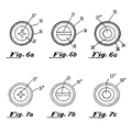
- This region of increased shaft thickness provides two valuable functions. First, it simplifies manufacturing of the screw since, the step-up in diameter from the screw shaft to the outer perimeter of the screw head 24, particularly if the flange 23 is used, is particularly difficult to manufacture. Second, it provides for increased volume of material where a Phillips style screw driver recess (see Fig. 6a) or a Torx style (not shown) recess is used.
- a typical captive screw of the present invention is preferably as follows. Integral to the head 24 of the screw 20 is a driving recess, for example, a recessed slot 27 (see FIGS. 2-4, 6b, and 7b), for use with a slotted-type screwdriver. As shown in FIGS. 6a, 6c, 7a, and 7c, alternate embodiments may include a Phillips-type recess 27' for use with a Phillips-type screwdriver, a socket recess 27" for use with a socket wrench or any other drive recess as is known in the art, for example a Torx recess.
- a driving recess for example, a recessed slot 27 (see FIGS. 2-4, 6b, and 7b)
- alternate embodiments may include a Phillips-type recess 27' for use with a Phillips-type screwdriver, a socket recess 27" for use with a socket wrench or any other drive recess as is known in the art, for example a Tor
- axial scored lines 36 disposed on the outer circumferential surface 34 of the knob 30 to facilitate tightening of the retractable captive screw 10 using only fingers, without tools, or to facilitate the initial alignment of the screw threads of the screw threaded shaft 22 with a threaded hole in a second panel 62.
- Alternate embodiments may include a knurling pattern or other frictional surface (not shown) or a smooth surface knob 30" such as that shown in FIGS. 7a, 7b, and 7c.
- the knob 30 is attached to the ferrule 50, however, full rotational movement of the knob 30 with respect to the ferrule 50, and a limited amount of axial movement of the knob 30 with respect to the ferrule 50, preferably corresponding to screw engagement length, are provided.
- the limited axial movement is accomplished by a first annular flange 35 on the knob 30 extending inward from the inner surface 38 of the hollow knob 30 towards the threaded shaft 22, in combination with a second annular flange 56, integral to the ferrule 50, extending outward from the body of the ferrule 50 at the knob end or first end of the ferrule 50.
- the inner surface 38 of the hollow knob 30 has a larger diameter than the outside diameter of the second annular flange 56 of ferrule 50 such that a portion of the ferrule 50 is slidable within the hollow cylindrical body 32 of the knob 30.
- a spring 40 Encased between the lower end of the ferrule 50 and the head 24 of the screw 20 is a spring 40.
- a spring 40 Preferably at the lower end or second end of the ferrule 50, adjacent the panel attachment means 52, is an annular surface 57 protruding inwardly toward the axial center of the ferrule. This annular surface 57 serves to function as a termination point for one end of spring 40.
- the opposite end of spring 40 is terminated at the underside of screw head 24, as depicted in FIGS. 2 and 3.
- the knob 30 Is at its lowest position, i.e. the upper end of the ferrule 50 is in contact with the underside of the screw head 24.
- the screw 20 is inserted in the lower panel to its limit.
- the knob 30 is at its most extended position, i.e. the first annular flange 35 on the knob 30 and the second annular flange 56 on the ferrule are in contact with each other as described above.
- the panel attachment means 52 may be any such means known in the art, e.g. press-in as depicted in the present figures, snap-in as depicted in U.S. Patent No. 5, 382, 124, swaged, screwed, or the like, as is known in the art.
- the new knob/screw interface allows the steel screw 20 to directly contact the steel or aluminum ferrule over a wider area due to the increased width of the annular flange 23, thereby eliminating the aluminum/steel interface of some prior captive screws.
- This area of increased surface provides improved structure for pressing the captive screw into a panel 60.
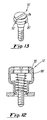
- FIGS. 12 and 13 An alternate embodiment 10' of the captive screw of the present invention is depicted in FIGS. 12 and 13.
- the advantages described above for the first embodiment specifically with respect to the additional annular flange 23 are reduced, however, this embodiment can be manufactured less expensively due to the reduced complexity.
- This embodiment does retain the advantages of the structure by virtue of the fact that the screw 20' installs through the bottom of the knob, rather than the top, as in prior art screws.
Landscapes
- Engineering & Computer Science (AREA)
- General Engineering & Computer Science (AREA)
- Mechanical Engineering (AREA)
- Connection Of Plates (AREA)
- Dowels (AREA)
Claims (19)
- Vis captive (10) destinée à être fixée à un panneau (60) pour la fixation du panneau à une surface (62), la surface ayant un trou taraudé, la vis captive comprenant :a) une vis (20) possédant une partie de tête (24) et une tige (22) ayant au moins une partie filetée, la partie de tête ayant une face inférieure et un périmètre externe (25),b) un bouton (30) fixé rigidement à la partie de tête (24), le bouton ayant une surface interne, etc) une virole (50) ayant une première extrémité et une seconde extrémité par laquelle passe la tige, la virole ayant un dispositif (52) de fixation à un panneau à la seconde extrémité afin que la vis captive soit fixée au panneau,d) la partie de tête (24) ayant plusieurs saillies (26) placées au périmètre externe de la partie de tête, les saillies (26) étant solidaires de la partie de tête (24) de la vis, et les saillies (26) fixant rigidement la partie de tête (24) de la vis à la surface interne du bouton (30) pour former une interface bouton-vis de résistance accrue,
la vis captive étant caractérisée en ce que :e) la face inférieure de la partie de tête (24) de la vis est en contact direct avec la première extrémité de la virole (50) lorsque la vis (20) est en position totalement avancée,
de sorte qu'une charge appliquée à la vis et due au serrage de la vis est directement encaissée par la virole (50) et que la rupture du bouton est réduite. - vis captive selon la revendication 1, dans laquelle la partie de tête (24) de la vis a une extrémité inférieure, la vis captive étant en outre caractérisée en ce que la partie de tête de la vis possède un flasque annulaire (23) entourant l'extrémité inférieure de la partie de tête de la vis, le flasque annulaire (23) ayant un périmètre externe, et les saillies (26) sont disposées au périmètre externe du flasque annulaire.
- Vis captive selon la revendication 2, caractérisée en outre en ce que la vis (20) est poussée par pression dans le bouton (30) pendant l'assemblage, et le flasque annulaire (23) constitue une butée positive lorsque la vis est poussée par pression dans le bouton.
- vis captive selon la revendication 1, 2 ou 3, dans laquelle la partie de tête (24) de la vis a une extrémité inférieure, la vis captive étant en outre caractérisée en ce que la partie de tête de la vis comprend un chanfrein annulaire (29) proche de l'extrémité inférieure de la partie de tête de la vis, et le matériau de la surface interne du bouton (30) remplit le chanfrein annulaire (29) pour assurer une fixation supplémentaire du bouton sur la vis.
- Vis captive selon la revendication 1, 2 ou 3, dans laquelle la partie de tête (24) de la vis a une extrémité inférieure, la vis captive étant en outre caractérisée en ce que la partie de tête de la vis comporte un chanfrein annulaire (29) proche de l'extrémité inférieure de la partie de tête de la vis et permettant le fluage du matériau de la surface interne du bouton (30) dans le chanfrein annulaire (29) pendant l'assemblage par application d'une pression afin que le bouton soit fixé de façon supplémentaire à la vis.
- vis captive selon la revendication 1, 2, 3, 4 ou 5, caractérisée en outre en ce que les saillies (26) sont emmanchées à force à la surface interne du bouton (30), les saillies déplaçant le matériau dans le bouton pour assurer la fixation rigide du bouton à la vis.
- Vis captive selon la revendication 6, dans laquelle le bouton (30) a une extrémité supérieure et une partie inférieure, la vis captive étant en outre caractérisée en ce que le bouton possède une région d'épaisseur accrue (33) proche de l'extrémité supérieure du bouton, et les saillies (26) déplacent le matériau de la région d'épaisseur accrue (33) afin que la vis soit ainsi rigidement fixée au bouton.
- Vis captive selon la revendication 1, 2, 3, 4, 5, 6 ou 7, dans laquelle le bouton (30) a une extrémité supérieure et une partie inférieure, et caractérisée en outre en ce que le bouton a une construction permettant l'insertion de la vis (20) dans le bouton par la partie inférieure du bouton plutôt que par l'extrémité supérieure du bouton.
- Vis captive selon la revendication 1, 2, 3, 4, 5, 6, 7 ou 8, caractérisée en outre en ce que les saillies (26) ont une section de forme générale rectangulaire.
- Vis captive (10) destinée à être fixée à un panneau (60) pour la fixation du panneau à une surface (62), la surface ayant un trou taraudé, la vis captive comprenant :a) une vis (20) possédant une partie de tête (24) et une tige (22) ayant au moins une partie filetée, la partie de tête ayant une face inférieure et un périmètre externe (25),b) un bouton (30) fixé rigidement à la partie de tête (24), le bouton (30) ayant une surface interne, etc) une virole (50) ayant une première extrémité et une seconde extrémité par laquelle passe la tige (22), la virole (50) ayant un dispositif (52) de fixation à un panneau à la seconde extrémité afin que la vis captive soit fixée au panneau,
la vis captive étant caractérisée en ce que :d) la partie de tête (24) de la vis a une extrémité inférieure, et la partie de tête de la vis comprend un chanfrein annulaire (29) proche de l'extrémité inférieure de la partie de tête (24) de la vis, et le matériau de la surface interne du bouton (30) remplit le chanfrein annulaire (29) afin que le bouton soit fixé à la vis. - Vis captive selon la revendication 10, caractérisée en ce que la face inférieure de la partie de tête (24) de la vis est en contact direct avec la première extrémité de la virole (50) lorsque la vis (20) est en position totalement avancée,
de sorte qu'une charge appliquée à la vis pendant le serrage de la vis est directement encaissée par la virole (50) et la rupture du bouton est ainsi réduite. - Vis captive selon la revendication 10 ou 11, dans laquelle la partie de tête (24) de la vis a une extrémité inférieure, la vis captive étant en outre caractérisée en ce que la partie de tête de la vis possède un flasque annulaire (23) placé autour de l'extrémité inférieure de la partie de tête (24) de la vis, le flasque annulaire (23) ayant une surface inférieure, et le chanfrein annulaire (29) étant disposé à la surface inférieure du flasque annulaire (23).
- Vis captive selon la revendication 12, dans laquelle le bouton (30) a une extrémité supérieure et une partie inférieure, la vis captive étant en outre caractérisée en ce que la vis (20) est repoussée par pression dans le bouton (30) pendant l'assemblage, le bouton (30) a une construction permettant l'insertion de la vis (20) dans le bouton par la partie inférieure du bouton plutôt que par l'extrémité supérieure du bouton, et le flasque (23) forme une butée positive lorsque la vis (20) est poussée par pression dans le bouton (30) par la partie inférieure du bouton.
- Procédé de fabrication d'une vis captive selon l'une quelconque des revendications 1 à 9, comprenant les étapes suivantes :la mise à disposition d'une vis (20) ayant une tête (24) qui a un périmètre externe (25) délimitant un diamètre de tête,la disposition d'un bouton (30) ayant une surface interne de diamètre interne, le bouton ayant aussi une extrémité supérieure et une partie inférieure,la fixation rigide de la vis (20) au bouton (30),la disposition d'une virole (50), etla capture de la vis (20) sur la virole (50) de manière que le bouton (30) puisse avoir un mouvement complet de rotation et une amplitude limitée de déplacement axial par rapport à la virole,le procédé de fabrication d'une vis captive étant en outre caractérisé en ce que :le diamètre interne est égal ou inférieur de façon générale au diamètre de la tête (24) de la vis,la tête de vis (24) comporte plusieurs saillies (26) dépassant du périmètre externe de la tête de la vis, les saillies étant solidaires de la tête de la vis, etl'étape de fixation rigide de la vis au bouton comprend une étape de poussée par pression de la tête de vis (24) dans le bouton (30) par la partie inférieure du bouton de manière que les saillies (26) déplacent du matériau dans le bouton et assurent un emmanchement à force à la surface interne du bouton (30) par les saillies et ainsi la fixation rigide du bouton (30) sur la vis (20).
- Procédé de fabrication d'une vis captive selon la revendication 14, dans lequel la partie de tête (24) de la vis a une extrémité inférieure, le procédé étant en outre caractérisé par la disposition d'un flasque annulaire (23) autour de l'extrémité inférieure de la partie de tête de la vis, le flasque annulaire (23) étant solidaire de la partie de tête de la vis et ayant un périmètre externe, et les saillies (26) sont disposées au périmètre externe du flasque annulaire.
- Procédé de fabrication d'une vis captive selon la revendication 15, caractérisé en outre en ce que le flasque annulaire (23) forme une butée positive lorsque la vis (20) est poussée par pression dans le bouton (30).
- Procédé de fabrication d'une vis captive selon la revendication 14, 15 ou 16, dans lequel la partie de tête (24) de la vis a une extrémité inférieure, le procédé étant en outre caractérisé par la disposition d'un chanfrein annulaire (29) près de l'extrémité inférieure de la partie de tête de la vis pour permettre le fluage du matériau de la surface interne du bouton (30) dans le chanfrein annulaire (29) pendant l'assemblage par poussée par pression afin que le bouton (30) soit fixé de façon supplémentaire à la vis (20).
- Procédé de fabrication d'une vis captive selon l'une quelconque des revendications 10 à 13, comprenant les étapes suivantes :la disposition d'une vis (20) ayant une tête (24) possédant une extrémité inférieure et un périmètre externe (25) qui délimite un diamètre de tête,la disposition d'un bouton (30) ayant une surface interne de diamètre interne,la fixation rigide de la vis (20) au bouton (30),la disposition d'une virole (50), etla capture de la vis (20) par la virole de manière que le bouton (30) puisse présenter un mouvement complet de rotation et une amplitude limitée de déplacement axial par rapport à la virole (50),le procédé de fabrication d'une vis captive étant en outre caractérisé en ce que :le diamètre interne est inférieur ou égal de façon générale au diamètre de la tête (24) de la vis,un chanfrein annulaire (29) est disposé près de l'extrémité inférieure de la partie de tête (24) de la vis, etl'étape de fixation rigide de la vis (20) au bouton (30) comprend des étapes de poussée par pression de la tête (24) et de la vis dans le bouton (30) et de fluage du matériau de la surface interne du bouton (30) dans le chanfrein annulaire (29) afin que le bouton (30) soit fixé rigidement à la vis (20).
- Procédé de fabrication d'une vis captive selon la revendication 18, caractérisé par la disposition d'un flasque annulaire (23) autour de l'extrémité inférieure de la partie de tête (24) de la vis, le flasque annulaire (23) étant solidaire de la partie de tête (24) de la vis, le flasque annulaire (23) formant une butée positive lorsque la vis (20) est poussée par pression dans le bouton (30).
Applications Claiming Priority (5)
| Application Number | Priority Date | Filing Date | Title |
|---|---|---|---|
| US59577 | 1998-04-14 | ||
| US09059577 US5851095C1 (en) | 1998-04-14 | 1998-04-14 | Captive screw |
| US09/224,129 US6280131B1 (en) | 1998-04-14 | 1998-12-17 | Captive screw |
| US224129 | 1998-12-17 | ||
| PCT/US1999/005564 WO1999053206A2 (fr) | 1998-04-14 | 1999-03-16 | Vis imperdable |
Publications (3)
| Publication Number | Publication Date |
|---|---|
| EP1075603A2 EP1075603A2 (fr) | 2001-02-14 |
| EP1075603A4 EP1075603A4 (fr) | 2001-05-30 |
| EP1075603B1 true EP1075603B1 (fr) | 2004-10-27 |
Family
ID=26738930
Family Applications (1)
| Application Number | Title | Priority Date | Filing Date |
|---|---|---|---|
| EP99911394A Expired - Lifetime EP1075603B1 (fr) | 1998-04-14 | 1999-03-16 | Vis imperdable |
Country Status (9)
| Country | Link |
|---|---|
| US (1) | US6468012B2 (fr) |
| EP (1) | EP1075603B1 (fr) |
| JP (1) | JP2002511553A (fr) |
| CN (1) | CN1153011C (fr) |
| AU (1) | AU3004399A (fr) |
| BR (1) | BR9909608A (fr) |
| CA (1) | CA2328222A1 (fr) |
| DE (1) | DE69921466T2 (fr) |
| WO (1) | WO1999053206A2 (fr) |
Families Citing this family (57)
| Publication number | Priority date | Publication date | Assignee | Title |
|---|---|---|---|---|
| EP1379789B1 (fr) * | 2001-04-20 | 2006-11-02 | Pem Management, Inc. | Attache de panneau hybride avec bouchon cliquetable |
| US6802656B2 (en) | 2001-11-30 | 2004-10-12 | Pelco | Retained hardware system and method |
| US6786691B2 (en) * | 2002-05-07 | 2004-09-07 | Tyco Electronics Corporation | Load cell for securing electronic components |
| TWI309279B (en) * | 2002-12-18 | 2009-05-01 | Southco | Low profile captive screw |
| US6860693B2 (en) * | 2003-02-14 | 2005-03-01 | Dell Products L.P. | Rapid fastening screw apparatus and method |
| US20040240962A1 (en) * | 2003-05-29 | 2004-12-02 | Wen-I Teng | Captive screw |
| US7156084B1 (en) * | 2003-06-30 | 2007-01-02 | Jdl Engineering, Llc | Paint-ball sport gun with adjustable detent assembly |
| US6955512B2 (en) * | 2003-07-21 | 2005-10-18 | Hewlett-Packard Development Company, L.P. | Mounting device for securing an electronic device to an equipment rack |
| TWM243584U (en) * | 2003-09-05 | 2004-09-11 | Hon Hai Prec Ind Co Ltd | Captive screw |
| US7134211B2 (en) | 2004-03-18 | 2006-11-14 | Black & Decker Inc. | Laser level |
| DE202005015860U1 (de) * | 2005-10-10 | 2005-12-08 | Böllhoff Verbindungstechnik GmbH | Vorrichtung zum Verschrauben zweier Bauteile mit Toleranzausgleich |
| USD551068S1 (en) * | 2005-10-14 | 2007-09-18 | Hon Hai Precision Industry Co., Ltd. | Flex bolt |
| USD551956S1 (en) * | 2005-10-14 | 2007-10-02 | Hon Hai Precision Industry Co., Ltd. | Flex bolt |
| USD551957S1 (en) * | 2005-10-14 | 2007-10-02 | Hon Hai Precision Industry Co., Ltd. | Flex bolt |
| USD551958S1 (en) * | 2005-10-14 | 2007-10-02 | Hon Hai Precision Industry Co., Ltd. | Flex bolt |
| USD551955S1 (en) * | 2005-10-14 | 2007-10-02 | Hon Hai Precision Industry Co., Ltd. | Flex bolt |
| US20090044388A1 (en) * | 2007-08-14 | 2009-02-19 | Shin Zu Shing Co., Ltd. | Quick release strap connector |
| US8011867B2 (en) * | 2008-03-25 | 2011-09-06 | Dell Products, Lp | Flush captive screw with retractable knurled knob |
| US20100051007A1 (en) * | 2008-08-26 | 2010-03-04 | Smart Parts, Inc. | Sensor cover and angled ball detent for paintball gun |
| US8893369B2 (en) * | 2008-10-09 | 2014-11-25 | Ting-Jui Wang | Packaging structure for assembling to printed circuit board |
| US20100290861A1 (en) * | 2009-05-13 | 2010-11-18 | Kuo-Chung Wang | Metal plate member fixation device installation method |
| CN101592178B (zh) * | 2009-06-30 | 2010-12-08 | 蔡高涛 | 液压加压螺丝 |
| CN101941135B (zh) * | 2009-07-08 | 2012-09-19 | 王国仲 | 固定装置结构及其制造方法 |
| CN101992377B (zh) * | 2009-08-24 | 2012-09-05 | 王国仲 | 固定装置的组装方法 |
| US8074337B2 (en) * | 2009-09-24 | 2011-12-13 | Kuo-Chung Wang | Metal plate member fixation device installation method |
| US8161616B2 (en) * | 2009-09-25 | 2012-04-24 | Pem Management, Inc. | Method of manufacture for a plastic-capped panel fastener |
| US20110135421A1 (en) * | 2009-12-09 | 2011-06-09 | Ming-Chung Chiu | Metal plate member fixation device |
| CN102238836A (zh) * | 2010-04-28 | 2011-11-09 | 鸿富锦精密工业(深圳)有限公司 | 固定组件 |
| EP2405146B1 (fr) * | 2010-07-09 | 2014-12-10 | VEGA Grieshaber KG | Dispositif de montage pour la fixation d'un bloc sur un composant, notamment sur un boîtier extérieur d'un composant supplémentaire |
| KR101238750B1 (ko) | 2010-08-31 | 2013-03-11 | 주식회사 이건창호 | 프레임 및 창살과 이를 이용한 창호, 이를 위한 결합 부재 |
| US20120189400A1 (en) * | 2011-01-20 | 2012-07-26 | Ming-Chung Chiu | Floating fastener |
| TW201241331A (en) * | 2011-04-12 | 2012-10-16 | Ting-Jui Wang | Modular quick assembling device |
| US8827614B2 (en) * | 2012-08-30 | 2014-09-09 | Hanwit Precision Industries Ltd. | Floating fastener allowing a high pre-positioning tolerance |
| US9695852B2 (en) | 2012-09-09 | 2017-07-04 | Hanwit Precision Industries Ltd. | Floating fastener mounting structure |
| US20140068921A1 (en) | 2012-09-09 | 2014-03-13 | Hanwit Precision Industries Ltd. | Floating fastener mounting structure and method |
| US9746015B2 (en) | 2012-09-09 | 2017-08-29 | Hanwit Precision Industries Ltd. | Floating fastener mounting structure |
| TWM472768U (zh) * | 2013-08-29 | 2014-02-21 | Dtech Prec Ind Co Ltd | 固定組件 |
| US20150071730A1 (en) * | 2013-09-12 | 2015-03-12 | Hanwit Precision Industries Ltd. | Floating fastener |
| CN104006049A (zh) * | 2014-06-05 | 2014-08-27 | 常州市南飞机械有限公司 | 多功能便利弹簧螺钉 |
| CN104632831A (zh) * | 2014-11-10 | 2015-05-20 | 无锡市天力五金弹簧厂 | 弹簧组合螺钉 |
| WO2016205282A1 (fr) * | 2015-06-15 | 2016-12-22 | Antosh Kevin M | Ensemble élément de fixation de panneau captif à entraînement hélicoïdal |
| US20200346415A1 (en) * | 2015-11-20 | 2020-11-05 | Dtech Precision Industries Co., Ltd. | Fastener structure of fixing component and the fixing component |
| CN105508368B (zh) * | 2016-01-13 | 2018-01-30 | 中国航空动力机械研究所 | 一种系留式紧固组件 |
| DE102016206378A1 (de) * | 2016-04-15 | 2017-10-19 | Bayerische Motoren Werke Aktiengesellschaft | Verbindungsanordnung eines ersten Bauelements an einem zweiten Bauelement, insbesondere für ein Fahrzeug, sowie Verbindungsvorrichtung, insbesondere für ein Fahrzeug |
| US10041518B1 (en) | 2017-01-09 | 2018-08-07 | Heartland Precision Fasteners, Inc. | Captive screw |
| DE102017210406A1 (de) * | 2017-06-21 | 2018-12-27 | Bayerische Motoren Werke Aktiengesellschaft | Stromverteiler eines Fahrzeugs |
| JP2019086036A (ja) * | 2017-11-02 | 2019-06-06 | トヨタ自動車株式会社 | 部品締結構造 |
| US11078950B2 (en) * | 2018-02-26 | 2021-08-03 | Raytheon Company | Fastener biasing system |
| DE102018118617A1 (de) * | 2018-08-01 | 2020-02-06 | Otto Ganter Gmbh & Co. Kg Normteilefabrik | Rastbolzen mit geschützter Rastmechanik |
| US11607929B2 (en) * | 2018-08-09 | 2023-03-21 | Hanon Systems | Thermal cycle resistant fastening system for refrigerant fitting |
| US11083181B2 (en) * | 2019-07-12 | 2021-08-10 | Rocco Nicola Priore | Detachable weight assembly for fishing lure |
| JP2023521152A (ja) * | 2020-04-09 | 2023-05-23 | サウスコ,インコーポレイティド | キャプティブファスナ及びその組立て方法 |
| CN112178036B (zh) * | 2020-09-28 | 2022-02-22 | 若宇检具股份有限公司 | 一种螺纹自锁装置 |
| CN113374766A (zh) * | 2021-07-21 | 2021-09-10 | 杨福起 | 浮动螺纹式铆钉 |
| DE102022212056A1 (de) | 2022-11-14 | 2024-05-16 | Mahle International Gmbh | Montageeinheit und Montageanordnung |
| CN116293546A (zh) * | 2023-05-19 | 2023-06-23 | 广州鹏林照明灯具有限公司 | 一种雾化结构和舞台灯 |
| CN220185560U (zh) * | 2023-06-12 | 2023-12-15 | 讯凯国际股份有限公司 | 浮动螺丝 |
Family Cites Families (84)
| Publication number | Priority date | Publication date | Assignee | Title |
|---|---|---|---|---|
| CA766082A (en) | 1967-08-29 | K. Barry John | Stand-off for retractable screw fastener | |
| US436532A (en) | 1890-09-16 | Machine for producing linotypes | ||
| CA558456A (fr) | 1958-06-10 | Dzus William | Dispositif d'agrafage filete | |
| US3126935A (en) | 1964-03-31 | Retractable screw fastener | ||
| US748078A (en) | 1903-08-03 | 1903-12-29 | Stromberg Carlson Telephone | Fastening device. |
| US1166345A (en) | 1915-05-24 | 1915-12-28 | Arrow Electric Co | Switch-handle. |
| US1188420A (en) | 1916-01-25 | 1916-06-27 | James Eadie | Nut-lock. |
| US1664820A (en) | 1925-08-11 | 1928-04-03 | Hughes Charles Leopold | Window fastener |
| US2006359A (en) | 1933-07-03 | 1935-07-02 | Rolph J Lackner | Nut lock |
| US2151255A (en) | 1939-01-03 | 1939-03-21 | Lufkin Rule Co | Spring nut |
| US2331322A (en) | 1941-01-23 | 1943-10-12 | Lester E Hutson | Nut anchor |
| US2503189A (en) | 1946-01-14 | 1950-04-04 | Wittek Mfg Co | Clamp tightener |
| US2553236A (en) | 1946-12-13 | 1951-05-15 | Goodrich Co B F | Self-aligning nut assembly |
| US2470927A (en) | 1947-01-10 | 1949-05-24 | South Chester Corp | Fastening means |
| US2464133A (en) | 1947-02-19 | 1949-03-08 | William B Herbert | Jig nut |
| GB626013A (en) | 1947-05-21 | 1949-07-07 | John Freeman Cuss | Improvements in door and like fasteners for aircraft or other stress bearing structures |
| GB625345A (en) | 1947-05-21 | 1949-06-27 | Charles Hill And Company Ltd | Improvements relating to screws and their manufacture |
| US2773574A (en) | 1954-03-08 | 1956-12-11 | Sweeney Mfg Co B K | Ratchet adapters for socket wrenches |
| US2831520A (en) | 1954-07-20 | 1958-04-22 | Northrop Aircraft Inc | Telescoping captive screw holder with stop means for screw |
| US3033260A (en) | 1954-12-03 | 1962-05-08 | Snow William Herbert | Anchor nut assembly with removable shim |
| GB825877A (en) | 1956-07-05 | 1959-12-23 | Brown David Ind Ltd | An improved construction of clamping-nut |
| US2967557A (en) * | 1956-11-23 | 1961-01-10 | Reeves Instrument Corp | Captive screw with sleeve to prevent engagement of the screw head with the work |
| US2987811A (en) | 1957-09-24 | 1961-06-13 | W F Curlee | Method of mounting a captive fastener |
| US3056197A (en) | 1960-02-17 | 1962-10-02 | Scovill Manufacturing Co | Method of making coupling ferrules |
| US3059736A (en) | 1960-03-30 | 1962-10-23 | Illinois Tool Works | Spring loaded retractable captured screw assembly |
| US3137336A (en) | 1960-05-12 | 1964-06-16 | Hi Shear Rivet Tool Company | Two-part panel fastener having resilient retaining means for retaining a screw |
| US3052942A (en) | 1960-06-01 | 1962-09-11 | Gen Electric | Releasable fastening assembly |
| US3074292A (en) | 1960-09-14 | 1963-01-22 | Anthony P Polmon | Knob and self-locking insert |
| US3180389A (en) | 1962-03-02 | 1965-04-27 | Frank Charles | Fastener-captive front panel |
| US3245450A (en) | 1962-06-29 | 1966-04-12 | Deutsch Fastener Corp | Self-retracting screw |
| US3204680A (en) | 1963-02-04 | 1965-09-07 | South Chester Corp | Stand-off for retractable screw fastener |
| US3195600A (en) | 1963-07-29 | 1965-07-20 | Raytheon Co | Captive screw devices |
| US3250559A (en) | 1963-10-14 | 1966-05-10 | Northrop Corp | Captive screw |
| US3209807A (en) | 1963-11-12 | 1965-10-05 | Automatic Elect Lab | Positive retention captive screw |
| US3263728A (en) | 1964-02-20 | 1966-08-02 | Republic Ind Corp | Captive bolt |
| US3279302A (en) | 1964-08-11 | 1966-10-18 | Henry J Modrey | Quick release panel fastener |
| US3244212A (en) | 1964-11-18 | 1966-04-05 | South Chester Corp | Retractable threaded fastener |
| US3346032A (en) * | 1966-01-18 | 1967-10-10 | Deutsch Fastener Corp | Floating captive screw |
| US3385341A (en) | 1966-02-21 | 1968-05-28 | Illinois Tool Works | Fastener device |
| US3343581A (en) | 1966-07-01 | 1967-09-26 | Northrop Corp | Captive screw fastener |
| FR1541778A (fr) | 1966-10-31 | 1968-10-11 | Deutsch Fastener Corp | Vis prisonnière et son procédé de fabrication |
| US3465803A (en) | 1967-07-26 | 1969-09-09 | Penn Eng & Mfg Corp | Captive screw device and a method for securing together the parts thereof |
| US3437119A (en) | 1967-07-26 | 1969-04-08 | Standard Pressed Steel Co | Captive bolt unit |
| US3564563A (en) | 1968-01-09 | 1971-02-16 | Rex Chainbelt Inc | Adjustable quick acting fastener |
| US3502130A (en) * | 1968-03-04 | 1970-03-24 | Deutsch Fastener Corp | Captive jacking screw |
| DK125337B (da) | 1971-01-27 | 1973-02-05 | Praestmark T | Snaplås. |
| US3912411A (en) | 1971-09-22 | 1975-10-14 | Robert H Moffat | Thread latching mechanism |
| US3892031A (en) | 1972-04-05 | 1975-07-01 | Southco | Method of capturing screw fastener |
| GB1457782A (en) | 1974-04-29 | 1976-12-08 | Dzus Fastener Europe | Quick release fasteners |
| US4007516A (en) | 1975-05-19 | 1977-02-15 | Richco Plastic Company | Quarter turn locking fastener device |
| US4047266A (en) | 1976-03-15 | 1977-09-13 | Southco, Inc. | Quick action fastener |
| FR2347126A2 (fr) | 1976-04-06 | 1977-11-04 | Glaenzer Spicer Sa | Dispositif pour le formage a froid de pieces metalliques |
| GB1579730A (en) | 1976-11-01 | 1980-11-26 | Delaney Gallay Dynamics Ltd | Self-locking fasteners |
| US4387497A (en) | 1980-11-07 | 1983-06-14 | Bulent Gulistan | Captive screw assembly method and product |
| US4367643A (en) | 1980-12-16 | 1983-01-11 | The Gleason Works | Method and apparatus for cold forming metal articles having irregular cross-section |
| US4952107A (en) | 1981-03-11 | 1990-08-28 | Dupree, Inc. | Captive panel screw assembly |
| US4398322A (en) | 1981-03-28 | 1983-08-16 | Ewen Warren E | Hitch pin assembly |
| US4399682A (en) | 1981-04-24 | 1983-08-23 | The Gleason Works | Method for cold forming metal articles having diverging members |
| US4594040A (en) | 1983-08-29 | 1986-06-10 | Deutsch Fastener Corp. | Panel fastener |
| USD283591S (en) | 1983-10-14 | 1986-04-29 | Penn Engineering & Manufacturing Corp. | Low profile panel fastener |
| US4602903A (en) | 1984-03-16 | 1986-07-29 | Wilburn James C | Anti-theft safety nut |
| US4621961A (en) | 1985-02-28 | 1986-11-11 | Bulent Gulistan | Captive panel fastener |
| US4692075A (en) | 1986-05-02 | 1987-09-08 | Norco,Inc. | Panel fastener |
| US4863326A (en) | 1986-12-11 | 1989-09-05 | Southco, Inc. | Captive fastener |
| US4915557A (en) | 1988-09-13 | 1990-04-10 | Rexnord Holdings Inc. | Captive screw assembly |
| DE3832359C1 (fr) | 1988-09-23 | 1989-11-02 | Reinhold 7801 Ebringen De Schmidt | |
| US4975007A (en) | 1989-06-07 | 1990-12-04 | Jorge Molina | Captive fastener |
| US5042880A (en) | 1990-04-10 | 1991-08-27 | Garuti Raymond R | Quick change wheel assembly |
| US5094579A (en) | 1990-10-19 | 1992-03-10 | Johnson H Thad | Fastener and grommet assembly providing axial play |
| US5146668A (en) | 1991-06-18 | 1992-09-15 | Bulent Gulistan | Method for manufacturing part for floating nut assembly |
| US5209018A (en) | 1992-03-12 | 1993-05-11 | Heinrich William I | Sliding patio door improvement |
| US5336028A (en) | 1993-04-13 | 1994-08-09 | Vsi Corporation | Captive screw assembly |
| USD357176S (en) | 1993-06-07 | 1995-04-11 | Penn Engineering & Manufacturing Corp. | Panel fastener |
| US5382124A (en) * | 1994-02-07 | 1995-01-17 | Southco, Inc. | Fully retractable captive screw |
| US5338139A (en) * | 1993-10-20 | 1994-08-16 | Penn Engineering & Manufacturing Corp. | Shrouded captive screw |
| US5429467A (en) | 1994-06-15 | 1995-07-04 | Illinois Tool Works Inc. | High torque screw and grommet fastener assembly |
| US5544992A (en) * | 1994-08-11 | 1996-08-13 | Huck International, Inc. | Panel fastener having composite turning knob |
| USD374172S (en) | 1995-03-10 | 1996-10-01 | Southco, Inc. | Captive nut |
| US5611654A (en) | 1995-08-02 | 1997-03-18 | Southco, Inc. | Captive nut |
| US5642972A (en) | 1995-11-06 | 1997-07-01 | Southco, Inc. | One-direction captive screw fastener |
| USD388316S (en) | 1996-01-22 | 1997-12-30 | Penn Engineering & Manufacturing Corp. | Panel fastener |
| US5910052A (en) | 1998-04-14 | 1999-06-08 | Southco, Inc. | Process for manufacturing a captive screw |
| US5851095C1 (en) | 1998-04-14 | 2001-10-16 | Southco | Captive screw |
| US5941669A (en) | 1998-06-18 | 1999-08-24 | Southco, Inc. | Jack-out captivated screw |
-
1999
- 1999-03-16 CN CNB998069132A patent/CN1153011C/zh not_active Expired - Lifetime
- 1999-03-16 CA CA002328222A patent/CA2328222A1/fr not_active Abandoned
- 1999-03-16 BR BR9909608-0A patent/BR9909608A/pt not_active Application Discontinuation
- 1999-03-16 EP EP99911394A patent/EP1075603B1/fr not_active Expired - Lifetime
- 1999-03-16 WO PCT/US1999/005564 patent/WO1999053206A2/fr not_active Ceased
- 1999-03-16 JP JP2000543733A patent/JP2002511553A/ja active Pending
- 1999-03-16 DE DE69921466T patent/DE69921466T2/de not_active Expired - Lifetime
- 1999-03-16 AU AU30043/99A patent/AU3004399A/en not_active Abandoned
-
2001
- 2001-07-24 US US09/911,940 patent/US6468012B2/en not_active Expired - Lifetime
Also Published As
| Publication number | Publication date |
|---|---|
| DE69921466D1 (de) | 2004-12-02 |
| WO1999053206A2 (fr) | 1999-10-21 |
| JP2002511553A (ja) | 2002-04-16 |
| AU3004399A (en) | 1999-11-01 |
| CN1304480A (zh) | 2001-07-18 |
| DE69921466T2 (de) | 2005-10-13 |
| WO1999053206A3 (fr) | 1999-12-09 |
| CN1153011C (zh) | 2004-06-09 |
| EP1075603A4 (fr) | 2001-05-30 |
| EP1075603A2 (fr) | 2001-02-14 |
| CA2328222A1 (fr) | 1999-10-21 |
| US20010041110A1 (en) | 2001-11-15 |
| BR9909608A (pt) | 2002-01-15 |
| US6468012B2 (en) | 2002-10-22 |
Similar Documents
| Publication | Publication Date | Title |
|---|---|---|
| US6468012B2 (en) | Captive screw | |
| US6280131B1 (en) | Captive screw | |
| US5382124A (en) | Fully retractable captive screw | |
| US5244325A (en) | Fastener assembly with axially slidable sleeve | |
| CA1307954C (fr) | Ensemble de fixation de cache-culbuteur | |
| US5611654A (en) | Captive nut | |
| JP4063907B2 (ja) | 押込み式ナット | |
| US6860689B1 (en) | Fastening assemblies and components thereof | |
| US4157674A (en) | Collar stud for use in plastic | |
| US4186645A (en) | Plastic plug, nut and stud fastener assembly | |
| CA2073731C (fr) | Methode d'assemblage d'un element de fixation | |
| US3995675A (en) | Captive panel fastener assembly | |
| US4705441A (en) | Self locking sheet metal screw | |
| US6176665B1 (en) | Threaded fastener and assembly | |
| US5104272A (en) | Method of installing as fastener in a support made of moulded soft material, fastener suitable for implementing this method, fixing incorporating said fastener, and support made of moulded soft material obtained by said method | |
| US5199152A (en) | Captivating a fastener to a workpiece | |
| US20010024607A1 (en) | Floating captive screw | |
| US6244549B1 (en) | Fitting adapted for holding spacedly a support member on an upright wall | |
| US7204668B2 (en) | Panel fastener with spring retaining ring | |
| US20080193249A1 (en) | Laminated nut with tension indicator | |
| US20050053446A1 (en) | Captive screw with receiving space | |
| CA1247407A (fr) | Organe d'assemblage resistant au cisaillement | |
| MXPA00010002A (en) | Captive screw | |
| CA2089625A1 (fr) | Ensemble de fixation extensible pour plaque de tete de poteau | |
| JP4043792B2 (ja) | フリーアクセスフロア |
Legal Events
| Date | Code | Title | Description |
|---|---|---|---|
| PUAI | Public reference made under article 153(3) epc to a published international application that has entered the european phase |
Free format text: ORIGINAL CODE: 0009012 |
|
| 17P | Request for examination filed |
Effective date: 20001103 |
|
| AK | Designated contracting states |
Kind code of ref document: A2 Designated state(s): DE ES FR GB IT |
|
| RIC1 | Information provided on ipc code assigned before grant |
Free format text: 7F 16B 21/18 A |
|
| A4 | Supplementary search report drawn up and despatched |
Effective date: 20010417 |
|
| AK | Designated contracting states |
Kind code of ref document: A4 Designated state(s): DE ES FR GB IT |
|
| RIC1 | Information provided on ipc code assigned before grant |
Free format text: 7F 16B 21/18 A, 7F 16B 41/00 B, 7F 16B 5/02 B |
|
| 17Q | First examination report despatched |
Effective date: 20011213 |
|
| GRAP | Despatch of communication of intention to grant a patent |
Free format text: ORIGINAL CODE: EPIDOSNIGR1 |
|
| GRAS | Grant fee paid |
Free format text: ORIGINAL CODE: EPIDOSNIGR3 |
|
| GRAA | (expected) grant |
Free format text: ORIGINAL CODE: 0009210 |
|
| AK | Designated contracting states |
Kind code of ref document: B1 Designated state(s): DE ES FR GB IT |
|
| PG25 | Lapsed in a contracting state [announced via postgrant information from national office to epo] |
Ref country code: IT Free format text: LAPSE BECAUSE OF FAILURE TO SUBMIT A TRANSLATION OF THE DESCRIPTION OR TO PAY THE FEE WITHIN THE PRESCRIBED TIME-LIMIT;WARNING: LAPSES OF ITALIAN PATENTS WITH EFFECTIVE DATE BEFORE 2007 MAY HAVE OCCURRED AT ANY TIME BEFORE 2007. THE CORRECT EFFECTIVE DATE MAY BE DIFFERENT FROM THE ONE RECORDED. Effective date: 20041027 Ref country code: FR Free format text: LAPSE BECAUSE OF FAILURE TO SUBMIT A TRANSLATION OF THE DESCRIPTION OR TO PAY THE FEE WITHIN THE PRESCRIBED TIME-LIMIT Effective date: 20041027 |
|
| REG | Reference to a national code |
Ref country code: GB Ref legal event code: FG4D |
|
| REF | Corresponds to: |
Ref document number: 69921466 Country of ref document: DE Date of ref document: 20041202 Kind code of ref document: P |
|
| PG25 | Lapsed in a contracting state [announced via postgrant information from national office to epo] |
Ref country code: ES Free format text: LAPSE BECAUSE OF FAILURE TO SUBMIT A TRANSLATION OF THE DESCRIPTION OR TO PAY THE FEE WITHIN THE PRESCRIBED TIME-LIMIT Effective date: 20050207 |
|
| PLBE | No opposition filed within time limit |
Free format text: ORIGINAL CODE: 0009261 |
|
| STAA | Information on the status of an ep patent application or granted ep patent |
Free format text: STATUS: NO OPPOSITION FILED WITHIN TIME LIMIT |
|
| 26N | No opposition filed |
Effective date: 20050728 |
|
| EN | Fr: translation not filed | ||
| PGFP | Annual fee paid to national office [announced via postgrant information from national office to epo] |
Ref country code: GB Payment date: 20180314 Year of fee payment: 20 Ref country code: DE Payment date: 20180306 Year of fee payment: 20 |
|
| REG | Reference to a national code |
Ref country code: DE Ref legal event code: R071 Ref document number: 69921466 Country of ref document: DE |
|
| REG | Reference to a national code |
Ref country code: GB Ref legal event code: PE20 Expiry date: 20190315 |
|
| PG25 | Lapsed in a contracting state [announced via postgrant information from national office to epo] |
Ref country code: GB Free format text: LAPSE BECAUSE OF EXPIRATION OF PROTECTION Effective date: 20190315 |