EP1075721B9 - Kabelklemme - Google Patents
Kabelklemme Download PDFInfo
- Publication number
- EP1075721B9 EP1075721B9 EP99918245A EP99918245A EP1075721B9 EP 1075721 B9 EP1075721 B9 EP 1075721B9 EP 99918245 A EP99918245 A EP 99918245A EP 99918245 A EP99918245 A EP 99918245A EP 1075721 B9 EP1075721 B9 EP 1075721B9
- Authority
- EP
- European Patent Office
- Prior art keywords
- clamp
- cable
- hook
- channel
- section
- Prior art date
- Legal status (The legal status is an assumption and is not a legal conclusion. Google has not performed a legal analysis and makes no representation as to the accuracy of the status listed.)
- Expired - Lifetime
Links
- 125000006850 spacer group Chemical group 0.000 claims description 18
- 238000000034 method Methods 0.000 claims description 3
- 230000005611 electricity Effects 0.000 abstract description 2
- 230000000295 complement effect Effects 0.000 description 2
- 238000012423 maintenance Methods 0.000 description 2
- 241000282887 Suidae Species 0.000 description 1
- 238000009434 installation Methods 0.000 description 1
- 230000007246 mechanism Effects 0.000 description 1
- 230000004048 modification Effects 0.000 description 1
- 238000012986 modification Methods 0.000 description 1
Images


Classifications
-
- H—ELECTRICITY
- H02—GENERATION; CONVERSION OR DISTRIBUTION OF ELECTRIC POWER
- H02G—INSTALLATION OF ELECTRIC CABLES OR LINES, OR OF COMBINED OPTICAL AND ELECTRIC CABLES OR LINES
- H02G7/00—Overhead installations of electric lines or cables
- H02G7/05—Suspension arrangements or devices for electric cables or lines
- H02G7/06—Suspensions for lines or cables along a separate supporting wire, e.g. S-hook
- H02G7/08—Members clamped to the supporting wire or to the line or cable
Definitions
- This invention relates to clamps for cables, in particular to in-line cable clamps for cables such as electricity or telecommunications cables.
- the J-hook is extremely simple and is familiar to those skilled in the art. It essentially comprises a J-shaped element and a fixing bolt.
- the J-shaped element has coaxial bores extending through the long and short arms, such that the fixing bolt can be extended through the short arm, the long arm, and a bore in the telegraph pole.
- the J-shaped element is affixed by the fixing bolt to the pole with the long arm affixed vertically adjacent to the pole, and the U-shaped section leading to the short arm extending outwards from the lower end of the long arm.
- the cable to be supported is rested on the U-shaped section when the bolt is being affixed, such that the fixing bolt closes the U-shaped portion of the J-shaped element and the cable is thereby attached relative to the pole.
- the long arm of the J-shaped element is provided with one or more additional apertures which receive secondary bolts which extend into the pole so as to prevent rotation of the J-hook around the axis defined by the fixing bolt (as might otherwise occur in high winds, for example).
- US-A-3,333,804 discloses a cable clamp and more particularly a clamp for use with an integrated messenger or "figure-8" telephone cable.
- the clamp includes a pair of jaw members each having at least one groove extending throughout its length adjacent and substantially parallel to one of the edge portions of the jaw member.
- the clamp may be mounted on the pole in association with a J-hook, which facilitates the installation of the cable. Initially the J-hook is secured to the pole by means of a nut and bolt. The cable is then strung between poles and rests on the U-shaped portion of the J-hook. Starting at a given pole, the lineman applies the clamp to the cable securing the jaw members thereto by means of nuts and bolts. The clamp is then positioned on the J-hook mounting bolt and a retaining nut endeavours to secure the clamp to this bolt.
- a disadvantage of a clamp of this type is that, if the cable becomes separated from the clamp, for example in strong winds, it will fly free from the pole and may be damaged as a consequence.
- the invention therefore provides a clamp for supporting a cable on a conventional J-hook having long and short arms and a fixing bolt passing through both arms, comprising two or more co-operating body sections which together define a channel which accommodates a portion of the cable in.use, means for fastening said sections together, means for supporting the clamp on the conventional J-hook, the clamp being supported in use on the fixing bolt between both arms of the J-hook, and at least one of the body sections being provided with a spacer extension which defines the width of the clamp between the arms of the J-hook, characterised in that said support means comprises a bore extending along an axis substantially perpendicular to the axis of said channel through said body sections, the bore being of a size sufficient to receive the conventional J-hook fixing bolt, in that the spacer extension is formed integrally with the body section and defines the width of the clamp along the axis of the bore, and in that said width is slightly less than the inner dimension between the arms of the J-hook at the position where the clamp is suspended, such that in use the
- the clamp provided by the invention has the advantage that by reliably and permanently supporting the cable out of contact with the J-hook, the problems associated with both chafing and dislodgement are overcome. This will reduce cable maintenance costs appreciably.
- the clamp is adapted for use with existing J-hook technology, the replacement of the many millions of existing cable supports is unnecessary. A simple modification (i.e. fitting the clamp to the cable and the J-hook) will enable these supports to continue to be used.
- a central portion of said channel is shaped to grip said portion of said cable when said body sections are fastened together.
- either end of the channel is of a belled shape to provide the cable with a degree of play at the ends of the channel.
- the fastening means comprises a nut and bolt arrangement and the body sections are provided with apertures positioned to receive said arrangement.
- means are provided for preventing rotation of a member of the nut and bolt arrangement relative to the body sections. This eases manipulation of the arrangement during assembly.
- the means for preventing rotation comprises one of said apertures being of non-circular cross-section, and one of the members of the nut and bolt arrangement having a portion thereof which is also of non-circular cross-section, said portion being received in said aperture such that when in position said member is prevented from rotating relative to said aperture.
- this arrangement allows a worker to use one hand for tightening the nut and bolt arrangement, which makes it easier and safer to fit clamps at the top of a telegraph pole.
- said aperture is a polygonal aperture and said portion of said member is a portion of the shank of the bolt, the shank having a similarly polygonal cross-section and being dimensioned sufficiently smaller than the aperture to enable it to be received therein, but not sufficiently small to allow it to rotate relative to the aperture when positioned therein.
- said aperture and said portion of the shank of said bolt are each of square cross-section.
- the body members are attached to one another with two substantially planar faces adjacent to one another, said faces being grooved to define said channel therebetween.
- the cross-section of the channel is of a closed shape. This enables the cable to be entirely accommodated within the channel, and the shape of the cross section can be chosen to match the cross-section of the cable. Internal surface features can be provided to increase grip.
- the cross-section of the channel is of an open shape.
- the cable to be gripped comprises a catenary or support strand attached to a parallel and substantially co-extensive signal carrying strand via connection means, and the clamp accommodates the catenary or support strand.
- Cables of this type are widely used for carrying telecommunications signals, the catenary strand being used to impart strength and to assist in end termination (when the cable terminates, the signal-carrying strand and catenary strand can be stripped apart from one another and the catenary strand can be lashed around the terminal telegraph pole). According to this aspect of the invention, however, the catenary strand is additionally used for the purposes of in-line support.
- connection means may extend, in use, out of the channel, such that the catenary or support strand is accommodated within the channel and the signal-carrying strand depends from said catenary or support strand and is located, in use, externally of the clamp.
- said spacer extension is hollow such that the interior thereof defines said bore.
- the fastening means permits the cable to be gripped more tightly as the fastening means is tightened. This assists in the fitting of clamps according to the invention, as discussed below.
- a clamp assembly comprising a clamp according to the invention supported by a J-hook.
- clamp of the present invention can be fitted as part of a clamp assembly or it can be "retro-fitted", i.e. added to existing J-hook supports.
- the invention provides, in further aspect thereof, a method of supporting a cable relative to a J-hook having long and short arms and a fixing bolt passing through both arms, comprising the steps of gripping the cable in a clamp provided with gripping means and support means, and attaching said clamp to the J-hook fixing bolt via said support means within the U-shaped portion of the J-hook, characterised in that said support means comprises a bore extending through the clamp along an axis substantially perpendicular to the axis of said gripping means, the bore being of a size sufficient to receive the conventional J-hook fixing bolt, in that the clamp has a spacer extension formed integrally with a body section thereof, said spacer extension defining the width of the clamp along the axis of the bore, and in that said width is slightly less than the inner dimension between the arms of the J-hook at the position where the clamp is suspended, such that in use the cable is suspended relative to but not in contact with said J-hook.
- the clamp comprises at least two body sections which together define a channel which accommodates a portion of the cable and means for fastening said sections together, said fastening means allowing the cable to be gripped more tightly as the fastening means is tightened, and wherein the step of gripping the cable in the clamp comprises initially gripping the cable lightly such that the clamp is slidable relative to the cable, then sliding the clamp along the cable into position relative to the J-hook, and subsequently tightening the fastening means to grip the cable tightly when the clamp is correctly positioned.
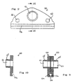
- a first body section of a cable clamp according to the invention.
- the body section 10 is provided with a bore 11 forming part of the support means, and two apertures 12,13 which are adapted to receive square-shanked bolts, as described further below.
- a groove 14 is provided on the reverse of the body section 10 (shown in dotted outline in Fig. 1). Referring additionally to Fig. 2 a cross-section of the body section 10 shows the bore 11 and the shape of the groove 14.
- a second body section 20 is shown.
- the body section 20 is also provided with a bore 21, apertures 22,23 and a groove 24.
- Fig. 4 shows that the bore 21 is provided in a spacer 25 formed integrally with the otherwise substantially planar body section 20, the spacer 25 extending out from both faces of the body section 20.
- Fig. 5 shows the body sections 10,20 in position for assembly together such that the spacer 25 protrudes through the bore 11 and such that the grooves 14,24 match up to form a channel 26.
- the apertures 12,13 (not shown in Fig. 5) in the body section 10 match up with the apertures 22,23 in the body section 20, such that a pair of bolts having a portion of their shanks of square cross-section can be passed through the overlapping pairs of apertures 12,22 and 13,23 to fasten the body sections 10,20 together when a complementary nut is applied to each bolt.
- the channel 26 has an open cross-section, i.e. it has a keyhole shape the function of which is related to the cable which is to be held.
- the body sections can be progressively brought closer to one another by tightening the nut and bolt arrangements, such that when the nut and bolt arrangements are fastened loosely together, the channel can slidably hold a cable, but when they are tightened, the channel grips the cable tightly.
- a worker can attach the clamp loosely around a cable near an existing J-hook, loosely fastening the nut-and bolt arrangements, and then the clamp can be slid along the cable into position in the J-hook. Once the clamp is secured to the J-hook and all other adjustments have been made, the nuts can be tightened to securely grip the cable relative to but not in contact with the J-hook.
- the clamp 30 comprising the body sections 10,20 and a pair of nut and bolt arrangements (one of which 31 is shown in Fig. 6) is illustrated in use.
- a J-hook comprising a J-shaped element 32, fixing bolt 33 and secondary bolt 34 is shown.
- the J-shaped element 32 is generally mounted on a pole (not shown) by means of the fixing bolt 33 which extends through the pole, and the secondary bolt 34 (in practice two or more may be used) is inserted into the pole to prevent rotation of the J-shaped element 32 around the axis of the fixing bolt 33.
- a cable (indicated generally at 35) is rested on the base of the U-shaped portion of the J-hook (defined below the fixing bolt 33)
- the cable clamp 30 is mounted on the fixing bolt 33 and the cable 35 is gripped by the clamp 30 such that in use the cable 35 is supported relative to but not in contact with the J-hook.
- the spacer 25 is dimensioned both in terms of width and internal diameter to receive the fixing bolt 33 therethrough and to fit between the arms of the J-shaped element 32.
- the cable 35 comprises a catenary or support strand 36 attached to a parallel and substantially co-extensive signal-carrying strand 37 via connection means 38.
- the keyhole shape of the open channel 26 allows the catenary strand 36 to be gripped therein and the connection means 38 to extend outside the channel 26, with the signal-carrying strand 37 depending therefrom.
- Fig. 7 shows a frontal view of a telegraph pole 40, on which a J-hook 41 is mounted by means of a fixing bolt 42 and a pair of secondary bolts 43,44.
- a cable clamp 45 according to the invention supporting a double stranded cable 46 is supported by the fixing bolt 42 as described above.
- Fig. 8 the belled or flared shape of the ends 27 of the channel 26 is shown.
- a cable 28 gripped by the central portion 29 of the channel 26 is thereby provided with a degree of play or movement at the ends 27 of the channel 26, thereby reducing the shear forces to which the cable would otherwise be subjected.
- a body section 50 is shown.
- the body section 50 is also provided with a bore 51 in a spacer 55 formed integrally with the otherwise substantially planar body section 50, apertures 52,53 and a groove 54.
- the spacer 55 extends out from only one face of the body section 50.
- Fig. 11 shows two such body sections 50 in position for assembly together such that the grooves 54 in each body section match up to form a channel 56.
- the apertures 52, 53 (not shown in Fig. 11) in each body section 50 match up such that a pair of bolts of square cross-section can be passed through the overlapping pairs of apertures 52 and 53 to fasten the body sections 50 together when a complementary nut is applied to each bolt
- the spacers 55 also match up "back to back" to provide a continuous bore 51-51 through the body sections 50 of the assembled clamp to accommodate the fixing bolt of a J-hook.
Landscapes
- Clamps And Clips (AREA)
- Insulated Conductors (AREA)
- Cable Accessories (AREA)
- Installation Of Indoor Wiring (AREA)
- Processing Of Terminals (AREA)
- Suspension Of Electric Lines Or Cables (AREA)
Claims (16)
- Klemme (30) zum Halten eines Kabels (35) in einem herkömmlichen J-förmigen Haken mit einem langen und einem kurzen Arm und einem durch beide Arme gehenden Befestigungsbolzen (33), die Folgendes umfasst: zwei oder mehr zusammenwirkende Körperabschnitte (10, 20; 50), die gemeinsam einen Kanal (26; 56) definieren, der im Gebrauch einen Abschnitt (36) des Kabels (35) aufnimmt, ein Mittel, um die Abschnitte (31) aneinander zu befestigen, und ein Mittel zum Halten der Klemme (30) in einem herkömmlichen J-förmigen Haken, wobei die Klemme (30) im Gebrauch an dem Befestigungsbolzen (33) zwischen beiden Armen des J-förmigen Hakens gehalten wird und mindestens einer der Körperabschnitte (10, 20; 50) mit einer Abstandhalterverlängerung (25; 55) versehen ist, die die Breite der Klemme (30) zwischen den Armen des J-förmigen Hakens definiert, dadurch gekennzeichnet, dass das Haltemittel eine Bohrung (51) aufweist, die sich entlang einer zur Achse des Kanals (26; 56) durch die Körperabschnitte (10, 20; 50) im Wesentlichen senkrecht verlaufenden Achse erstreckt und die groß genug ist, den herkömmlichen J-förmigen Befestigungsbolzen (33) aufzunehmen, dass die Abstandhalterverlängerung (25; 55) einstückig mit dem Körperabschnitt (10, 20; 50) ausgebildet ist und die Breite der Klemme (30) entlang der Achse der Bohrung (51) definiert, und dass die Breite in der Position, in der die Klemme (30) aufgehängt ist, etwas geringer als die innere Abmessung zwischen den Armen des J-förmigen Hakens ist, sodass das Kabel (35) im Gebrauch bezüglich des J-förmigen Hakens, aber nicht in Kontakt damit gehalten wird.
- Klemme nach Anspruch 1, bei der ein mittlerer Abschnitt des Kanals (26; 56) so gestaltet ist, dass er den Abschnitt (36) des Kabels (35) ergreift, wenn die Körperabschnitte (10, 20; 50) aneinander befestigt werden.
- Klemme nach Anspruch 1 oder 2, bei der beide Enden des Kanals (26; 56) glockenförmig sind, damit das Kabel (35) an den Enden des Kanals (26; 56) ein gewisses Spiel hat.
- Klemme nach einem der vorhergehenden Ansprüche, bei der das Befestigungsmittel (31) eine Anordnung (31) aus Bolzen und Mutter umfasst und die Körperabschnitte (10, 20; 50) Öffnungen (52, 53) aufweisen, die zur Aufnahme der Anordnung (31) positioniert sind.
- Klemme nach Anspruch 4, bei der Mittel vorgesehen sind, die verhindern, dass sich ein Glied der Anordnung (31) aus Bolzen und Mutter bezüglich der Körperabschnitte dreht.
- Klemme nach Anspruch 5, bei der bei dem Mittel zur Verhinderung einer Drehung vorgesehen ist, dass eine der Öffnungen (52, 53) keinen kreisförmigen Querschnitt hat und eines der Glieder der Anordnung (31) aus Bolzen und Mutter einen Abschnitt hat, der ebenfalls keinen kreisförmigen Querschnitt hat, wobei dieser Abschnitt in der Öffnung (52, 53) aufgenommen wird, sodass das Glied, wenn es sich in Position befindet, daran gehindert wird, sich bezüglich der Öffnung (52, 53) zu drehen.
- Klemme nach Anspruch 5 oder 6, bei der es sich bei der Öffnung (52, 53) um eine polygonale Öffnung (52, 53) und bei dem Abschnitt des Glieds um einen Abschnitt des Bolzenschafts handelt, wobei der Schaft einen ähnlich polygonalen Querschnitt hat und ausreichend kleiner als die Öffnung (52, 53) dimensioniert ist, sodass er darin aufgenommen werden kann, aber nicht so klein, dass er sich bezüglich der Öffnung (52, 53) dreht, wenn er darin positioniert ist.
- Klemme nach einem der Ansprüche 5 bis 7, bei der die Öffnung (52, 53) und der Abschnitt des Bolzenschafts jeweils einen quadratischen Querschnitt haben.
- Klemme nach einem der vorhergehenden Ansprüche, bei der die Körperglieder (10, 20; 50) mit zwei im Wesentlichen ebenen, einander benachbarten Flächen aneinander angebracht sind, die zur Definierung des Kanals (26; 56) zwischen sich genutet sind.
- Klemme nach einem der vorhergehenden Ansprüche, bei der der Querschnitt des Kanals eine geschlossene Form hat.
- Klemme nach einem der Ansprüche 1 bis 9, bei der der Querschnitt des Kanals (26; 56) eine offene Form hat.
- Klemme nach Anspruch 11, bei der das zu ergreifende Kabel (35) einen über Verbindungsmittel an einem parallelen und im Wesentlichen koextensiven Signalleitstrang (37) angebrachten Tragseil- oder Haltestrang (36) umfasst und die Klemme (30) den Tragseil- oder Haltestrang (36) aufnimmt.
- Klemme nach einem der vorhergehenden Ansprüche, dadurch gekennzeichnet, dass die Abstandhalterverlängerung (25; 55) hohl ist, sodass ihr Inneres die Bohrung (51) definiert.
- Klemmenanordnung mit einer von einem J-förmigen Haken gehaltenen Klemme (30) nach einem der vorhergehenden Ansprüche.
- Verfahren zum Halten eines Kabels (35) bezüglich eines J-förmigen Hakens mit einem langen und einem kurzen Arm und einem durch beide Arme gehenden Befestigungsbolzen (33), bei dem man das Kabel (35) in einer mit einem Greifmittel und einem Haltemittel versehenen Klemme (30) ergreift und die Klemme (30) über das Haltemittel im U-förmigen Abschnitt des J-förmigen Hakens an dem J-förmigen Befestigungsbolzen (33) anbringt, dadurch gekennzeichnet, dass das Haltemittel eine Bohrung (51) aufweist, die sich entlang einer zur Achse des Greifmittels im Wesentlichen senkrecht verlaufenden Achse durch die Klemme (30) erstreckt und die groß genug ist, den herkömmlichen J-förmigen Befestigungsbolzen (33) aufzunehmen, dass die Klemme (30) eine Abstandhalterverlängerung (25; 55) aufweist, die einstückig mit einem Körperabschnitt (10, 20; 50) davon ausgebildet ist und die Breite der Klemme (30) entlang der Achse der Bohrung (51) definiert, und dass die Breite in der Position, in der die Klemme (30) aufgehängt ist, etwas geringer als die innere Abmessung zwischen den Armen des J-förmigen Hakens ist, sodass das Kabel (35) im Gebrauch bezüglich des J-förmigen Hakens, aber nicht in Kontakt damit gehalten wird.
- Verfahren nach Anspruch 15, beim dem die Klemme (30) mindestens zwei Körperabschnitte (10, 20; 50) umfasst, die zusammen einen Kanal (26; 56) definieren, in dem ein Abschnitt des Kabels (36) und ein Mittel (31) zur Befestigung der Abschnitte aneinander aufgenommen wird, wobei das Kabel (35) dank des Befestigungsmittels (31) fester ergriffen werden kann, wenn das Befestigungsmittel (31) angezogen wird, und bei dem man beim Ergreifen des Kabels (35) in der Klemme (30) zunächst das Kabel (35) leicht ergreift, sodass die Klemme (30) bezüglich des Kabels (35) gleiten kann, dann die Klemme (30) am Kabel (35) entlang in Position bezüglich des J-förmigen Hakens schiebt und dabei das Befestigungsmittel (31) in Position bringt, und danach das Befestigungsmittel (31) anzieht, damit das Kabel (35) fest ergriffen wird, wenn die Klemme (30) korrekt positioniert ist.
Applications Claiming Priority (3)
| Application Number | Priority Date | Filing Date | Title |
|---|---|---|---|
| IE980333 | 1998-05-01 | ||
| IE980333 IES80482B2 (en) | 1998-05-01 | 1998-05-01 | A cable clamp |
| PCT/IE1999/000029 WO1999057792A1 (en) | 1998-05-01 | 1999-04-29 | A cable clamp |
Publications (3)
| Publication Number | Publication Date |
|---|---|
| EP1075721A1 EP1075721A1 (de) | 2001-02-14 |
| EP1075721B1 EP1075721B1 (de) | 2003-07-02 |
| EP1075721B9 true EP1075721B9 (de) | 2004-01-07 |
Family
ID=11041789
Family Applications (1)
| Application Number | Title | Priority Date | Filing Date |
|---|---|---|---|
| EP99918245A Expired - Lifetime EP1075721B9 (de) | 1998-05-01 | 1999-04-29 | Kabelklemme |
Country Status (6)
| Country | Link |
|---|---|
| EP (1) | EP1075721B9 (de) |
| AT (1) | ATE244466T1 (de) |
| AU (1) | AU3625299A (de) |
| DE (1) | DE69909282D1 (de) |
| IE (1) | IES80482B2 (de) |
| WO (1) | WO1999057792A1 (de) |
Families Citing this family (1)
| Publication number | Priority date | Publication date | Assignee | Title |
|---|---|---|---|---|
| JP2010538220A (ja) | 2007-08-29 | 2010-12-09 | エリコ インターナショナル コーポレイション | ケーブルサポートおよび方法 |
Family Cites Families (3)
| Publication number | Priority date | Publication date | Assignee | Title |
|---|---|---|---|---|
| US3141643A (en) * | 1961-12-21 | 1964-07-21 | Reliable Electric Co | Tangent support for messenger cable |
| US3333804A (en) * | 1965-09-16 | 1967-08-01 | Diamond Expansion Bolt Co Inc | Cable clamp |
| EP0632556A1 (de) * | 1993-06-28 | 1995-01-04 | Martin Waters | Ein Kabelträger |
-
1998
- 1998-05-01 IE IE980333 patent/IES80482B2/en not_active IP Right Cessation
-
1999
- 1999-04-29 AT AT99918245T patent/ATE244466T1/de not_active IP Right Cessation
- 1999-04-29 DE DE69909282T patent/DE69909282D1/de not_active Expired - Lifetime
- 1999-04-29 WO PCT/IE1999/000029 patent/WO1999057792A1/en not_active Ceased
- 1999-04-29 EP EP99918245A patent/EP1075721B9/de not_active Expired - Lifetime
- 1999-04-29 AU AU36252/99A patent/AU3625299A/en not_active Abandoned
Also Published As
| Publication number | Publication date |
|---|---|
| DE69909282D1 (de) | 2003-08-07 |
| EP1075721B1 (de) | 2003-07-02 |
| IES980333A2 (en) | 1998-08-12 |
| EP1075721A1 (de) | 2001-02-14 |
| WO1999057792A1 (en) | 1999-11-11 |
| IES80482B2 (en) | 1998-08-12 |
| ATE244466T1 (de) | 2003-07-15 |
| AU3625299A (en) | 1999-11-23 |
Similar Documents
| Publication | Publication Date | Title |
|---|---|---|
| US9379527B2 (en) | Stringing messenger clamp and methods of using the same | |
| US20090308021A1 (en) | Temporary Arm Gain and Saddle | |
| EP1075721B1 (de) | Kabelklemme | |
| CN113314911B (zh) | 一种预绞式跳线接续线夹 | |
| JP2007006625A (ja) | ルーズ式電線把持部 | |
| US3561708A (en) | Multipurpose cable clamp | |
| JP2004302418A (ja) | ケーブル留め具 | |
| US11482847B2 (en) | Aerial cable spacer insulator | |
| US20240372351A1 (en) | Dual Messenger Rolling Spacer | |
| JP2912907B1 (ja) | 配電線の空中分岐方法および配電線の空中分岐構造 | |
| US12473997B2 (en) | Breakaway cable attachment systems | |
| US4312495A (en) | Electrical transmission system conductor installation technique | |
| US8046888B2 (en) | Yoke assembly and method of installing same | |
| US11817691B2 (en) | Pole stringing bracket device and method of use | |
| RU2055433C1 (ru) | Поддерживающий зажим спирального типа для крепления волоконно-оптических кабелей линий связи или проводов воздушных линий электропередачи | |
| US4911388A (en) | Cable mounting bracket | |
| CN218118262U (zh) | 一种线夹用u型螺丝结构 | |
| CN216739277U (zh) | 一种拉索用碳纤维筋的锥套定位工装 | |
| US4429858A (en) | Electrical transmission system conductor installation technique | |
| JP2000139018A (ja) | ケーブル架設用の留め具 | |
| JP2015142399A (ja) | 耐張クランプ | |
| CN218597881U (zh) | 一种分体式复合绝缘横担 | |
| CN2678223Y (zh) | 电缆夹 | |
| KR0132567Y1 (ko) | 연합케이블의 지지대 | |
| JP3145530B2 (ja) | 引込電線の吊り金具 |
Legal Events
| Date | Code | Title | Description |
|---|---|---|---|
| PUAI | Public reference made under article 153(3) epc to a published international application that has entered the european phase |
Free format text: ORIGINAL CODE: 0009012 |
|
| 17P | Request for examination filed |
Effective date: 20001127 |
|
| AK | Designated contracting states |
Kind code of ref document: A1 Designated state(s): AT BE CH CY DE DK ES FI FR GB GR IE IT LI LU MC NL PT SE |
|
| 17Q | First examination report despatched |
Effective date: 20010626 |
|
| GRAH | Despatch of communication of intention to grant a patent |
Free format text: ORIGINAL CODE: EPIDOS IGRA |
|
| GRAH | Despatch of communication of intention to grant a patent |
Free format text: ORIGINAL CODE: EPIDOS IGRA |
|
| GRAA | (expected) grant |
Free format text: ORIGINAL CODE: 0009210 |
|
| AK | Designated contracting states |
Designated state(s): AT BE CH CY DE DK ES FI FR GB GR IE IT LI LU MC NL PT SE |
|
| PG25 | Lapsed in a contracting state [announced via postgrant information from national office to epo] |
Ref country code: NL Free format text: LAPSE BECAUSE OF FAILURE TO SUBMIT A TRANSLATION OF THE DESCRIPTION OR TO PAY THE FEE WITHIN THE PRESCRIBED TIME-LIMIT Effective date: 20030702 Ref country code: LI Free format text: LAPSE BECAUSE OF FAILURE TO SUBMIT A TRANSLATION OF THE DESCRIPTION OR TO PAY THE FEE WITHIN THE PRESCRIBED TIME-LIMIT Effective date: 20030702 Ref country code: IT Free format text: LAPSE BECAUSE OF FAILURE TO SUBMIT A TRANSLATION OF THE DESCRIPTION OR TO PAY THE FEE WITHIN THE PRESCRIBED TIME-LIMIT;WARNING: LAPSES OF ITALIAN PATENTS WITH EFFECTIVE DATE BEFORE 2007 MAY HAVE OCCURRED AT ANY TIME BEFORE 2007. THE CORRECT EFFECTIVE DATE MAY BE DIFFERENT FROM THE ONE RECORDED. Effective date: 20030702 Ref country code: FR Free format text: LAPSE BECAUSE OF FAILURE TO SUBMIT A TRANSLATION OF THE DESCRIPTION OR TO PAY THE FEE WITHIN THE PRESCRIBED TIME-LIMIT Effective date: 20030702 Ref country code: FI Free format text: LAPSE BECAUSE OF FAILURE TO SUBMIT A TRANSLATION OF THE DESCRIPTION OR TO PAY THE FEE WITHIN THE PRESCRIBED TIME-LIMIT Effective date: 20030702 Ref country code: CY Free format text: LAPSE BECAUSE OF FAILURE TO SUBMIT A TRANSLATION OF THE DESCRIPTION OR TO PAY THE FEE WITHIN THE PRESCRIBED TIME-LIMIT Effective date: 20030702 Ref country code: CH Free format text: LAPSE BECAUSE OF FAILURE TO SUBMIT A TRANSLATION OF THE DESCRIPTION OR TO PAY THE FEE WITHIN THE PRESCRIBED TIME-LIMIT Effective date: 20030702 Ref country code: BE Free format text: LAPSE BECAUSE OF FAILURE TO SUBMIT A TRANSLATION OF THE DESCRIPTION OR TO PAY THE FEE WITHIN THE PRESCRIBED TIME-LIMIT Effective date: 20030702 Ref country code: AT Free format text: LAPSE BECAUSE OF FAILURE TO SUBMIT A TRANSLATION OF THE DESCRIPTION OR TO PAY THE FEE WITHIN THE PRESCRIBED TIME-LIMIT Effective date: 20030702 |
|
| REG | Reference to a national code |
Ref country code: GB Ref legal event code: FG4D |
|
| REG | Reference to a national code |
Ref country code: CH Ref legal event code: EP |
|
| REG | Reference to a national code |
Ref country code: IE Ref legal event code: FG4D |
|
| REF | Corresponds to: |
Ref document number: 69909282 Country of ref document: DE Date of ref document: 20030807 Kind code of ref document: P |
|
| PG25 | Lapsed in a contracting state [announced via postgrant information from national office to epo] |
Ref country code: SE Free format text: LAPSE BECAUSE OF FAILURE TO SUBMIT A TRANSLATION OF THE DESCRIPTION OR TO PAY THE FEE WITHIN THE PRESCRIBED TIME-LIMIT Effective date: 20031002 Ref country code: PT Free format text: LAPSE BECAUSE OF FAILURE TO SUBMIT A TRANSLATION OF THE DESCRIPTION OR TO PAY THE FEE WITHIN THE PRESCRIBED TIME-LIMIT Effective date: 20031002 Ref country code: GR Free format text: LAPSE BECAUSE OF FAILURE TO SUBMIT A TRANSLATION OF THE DESCRIPTION OR TO PAY THE FEE WITHIN THE PRESCRIBED TIME-LIMIT Effective date: 20031002 Ref country code: DK Free format text: LAPSE BECAUSE OF FAILURE TO SUBMIT A TRANSLATION OF THE DESCRIPTION OR TO PAY THE FEE WITHIN THE PRESCRIBED TIME-LIMIT Effective date: 20031002 |
|
| PG25 | Lapsed in a contracting state [announced via postgrant information from national office to epo] |
Ref country code: DE Free format text: LAPSE BECAUSE OF FAILURE TO SUBMIT A TRANSLATION OF THE DESCRIPTION OR TO PAY THE FEE WITHIN THE PRESCRIBED TIME-LIMIT Effective date: 20031003 |
|
| PG25 | Lapsed in a contracting state [announced via postgrant information from national office to epo] |
Ref country code: ES Free format text: LAPSE BECAUSE OF FAILURE TO SUBMIT A TRANSLATION OF THE DESCRIPTION OR TO PAY THE FEE WITHIN THE PRESCRIBED TIME-LIMIT Effective date: 20031013 |
|
| NLV1 | Nl: lapsed or annulled due to failure to fulfill the requirements of art. 29p and 29m of the patents act | ||
| REG | Reference to a national code |
Ref country code: CH Ref legal event code: PL |
|
| PG25 | Lapsed in a contracting state [announced via postgrant information from national office to epo] |
Ref country code: LU Free format text: LAPSE BECAUSE OF NON-PAYMENT OF DUE FEES Effective date: 20040429 |
|
| PG25 | Lapsed in a contracting state [announced via postgrant information from national office to epo] |
Ref country code: MC Free format text: LAPSE BECAUSE OF NON-PAYMENT OF DUE FEES Effective date: 20040430 |
|
| PLBE | No opposition filed within time limit |
Free format text: ORIGINAL CODE: 0009261 |
|
| STAA | Information on the status of an ep patent application or granted ep patent |
Free format text: STATUS: NO OPPOSITION FILED WITHIN TIME LIMIT |
|
| 26N | No opposition filed |
Effective date: 20040405 |
|
| EN | Fr: translation not filed | ||
| PGFP | Annual fee paid to national office [announced via postgrant information from national office to epo] |
Ref country code: GB Payment date: 20120501 Year of fee payment: 14 |
|
| GBPC | Gb: european patent ceased through non-payment of renewal fee |
Effective date: 20130429 |
|
| PG25 | Lapsed in a contracting state [announced via postgrant information from national office to epo] |
Ref country code: GB Free format text: LAPSE BECAUSE OF NON-PAYMENT OF DUE FEES Effective date: 20130429 |
|
| PGFP | Annual fee paid to national office [announced via postgrant information from national office to epo] |
Ref country code: IE Payment date: 20180824 Year of fee payment: 20 |
|
| REG | Reference to a national code |
Ref country code: IE Ref legal event code: MK9A |
|
| PG25 | Lapsed in a contracting state [announced via postgrant information from national office to epo] |
Ref country code: IE Free format text: LAPSE BECAUSE OF EXPIRATION OF PROTECTION Effective date: 20190429 |