EP1075784A1 - Verfahrbarer Steinbrecher - Google Patents
Verfahrbarer Steinbrecher Download PDFInfo
- Publication number
- EP1075784A1 EP1075784A1 EP00402245A EP00402245A EP1075784A1 EP 1075784 A1 EP1075784 A1 EP 1075784A1 EP 00402245 A EP00402245 A EP 00402245A EP 00402245 A EP00402245 A EP 00402245A EP 1075784 A1 EP1075784 A1 EP 1075784A1
- Authority
- EP
- European Patent Office
- Prior art keywords
- rotor
- crusher according
- frame
- housing
- drive
- Prior art date
- Legal status (The legal status is an assumption and is not a legal conclusion. Google has not performed a legal analysis and makes no representation as to the accuracy of the status listed.)
- Withdrawn
Links
Images


Classifications
-
- A—HUMAN NECESSITIES
- A01—AGRICULTURE; FORESTRY; ANIMAL HUSBANDRY; HUNTING; TRAPPING; FISHING
- A01B—SOIL WORKING IN AGRICULTURE OR FORESTRY; PARTS, DETAILS, OR ACCESSORIES OF AGRICULTURAL MACHINES OR IMPLEMENTS, IN GENERAL
- A01B27/00—Clod-crushers
Definitions
- the present invention relates to shredders mobile stones like those moved by a tractor agricultural on the ground.
- the crusher also acts as a ripper of the soil to be treated and to do this, the cylindrical rotor carrying the hammers must be capable of being descended below the rolling or sliding level of the device on the ground.
- the tendency is to increasing the diameter of the rotor for reasons techniques related to the very design of the means of rotational drive of this rotor.
- the rotor is carried by the lower part of the side walls of the frame by means of two bearings and extends to the exterior of at least one of the two by a tree drive to which a pulley is coupled to the winding of several driving belts.
- the overall width of the mill is important compared to the useful working width, taking into account the overall width of the pulley; this bulk is all the more important as a number is required important of belts to transmit the torque necessary for the rotor to maintain performance acceptable work.
- the axial size of the pulley also requires the provision of large soles of the grinder on the ground to form shields of sufficient protection for pulleys. This width important soles is penalizing in some conditions of use of the crusher.
- the invention therefore relates to a mobile stone crusher with a frame comprising two braced sides forming a support for a rotor lower grinding perpendicular to the sides, for shoe insoles for the device on the ground and for means for rotating the rotor, one of which end portion extends outside of at least one sides of the frame.
- the rotor is wedged on a shaft drive through the corresponding flank and provided with a drive gear located at the outside of the flank crossed
- the means drive include a gearbox with an input gear and an output wheel formed by the toothed wheel of the drive shaft, the housing extending in an external plane and parallel to the flank crossed above and that the transmission box is mounted to pivot around the shaft axis of drive and against the effect of a mechanism hitch between the housing and the frame tending to maintain the housing in a determined position in exerting on it a couple around its axis of pivoting.
- the toothed wheel secured to the shaft drive can be a pinion or a wheel intended for welcome a chain. We know that such a provision allows to transmit a much larger torque than with a belt, of equal diameter.
- the pivoting of the case which occurs when the resistant effort encountered by the rotor is greater than the normal holding torque of the case, allows to absorb this resistant blow.
- a detection of this pivoting can also constitute the by means of a declutching control or any device to safeguard the means of transmission. This is how a pivot threshold sensor of the housing can be provided between the latter and the frame for output a safety signal likely to be operated as a command to stop the transmission of the rotor torque by cut-off of the motor or decoupling of two elements of the line transmission upstream of the rotor.
- the means of driving the rotor include two end portions which extend each outside the corresponding side of the frame of the grinder to attack the rotor at each end.
- the rotor has a second coaxial drive shaft on the first and crossing the corresponding side and also provided with a gear wheel drive located outside the flank crossed.
- the corresponding end part of the drive means also includes a transmission box with a input wheel and an output wheel formed by the wheel gear of the second drive shaft, this housing also being mounted pivoting around the axis common to the drive shafts therefore to that of rotor.
- the crusher of the invention comprises a frame 1 essentially comprising two lateral flanks 2 and 3 braced by sleepers such as those 4 shown at the front of the mill.
- This frame constitutes the support for various functional parts of the mill. It is as well as the cross 4 and a gallows 5 which is there associated in the upper part carries the three points 6, 7 and 8 for coupling the crusher to a tractor intended for the move in direction D.
- a grinding rotor 12 shown in the figure 2 by a circle symbolizing the volume envelope swept by the hammers that comprises in a manner known in itself this rotor 12.
- a anvil 13 which can be adjustable, extends between the sides 2 and 3 of the frame at a short distance from the rotor 12 equipped with his hammers. In some applications (scrub for example) the presence of this anvil is not essential.
- the direction of rotation of the rotor is indicated by arrow R so that the hammers force stones or other material with which they are in contact against the anvil 13, which break them down to a size such as the products can pass between the rotor and the anvil.
- FIG 3 we partially illustrated the rotor 12 and in particular its central hub 14 devoid of hammers with which it is normally fitted.
- This hub 14 is provided at each of its ends (only one is represented in the figure) of a cylindrical housing 15, of axis 16 coinciding with the axis of the hub 14 intended for accommodate a roller bearing 17.
- the rolling ring internal of these bearings is secured to a rocket 18 reported on the corresponding side 3 of the frame. We understands that by this mounting the support bearings of the rotor protrude outside the sides 2 and 3 only by the mounting flange 19 of the rockets 18.
- the hub 14 of the rotor is, at least on one side, provided with a drive shaft 20, passing through the spindle 18 which centers it on the axis 16 by means of support bearings 21 to project beyond the flange 19 by a grooved end 20 b .
- the drive shaft 20 is in reality in two successive parts 23 and 24, the part 23 being shrunk or mounted in the rotor by means of conical rings 25, 26 and its free end being harnessed to the inner end of part 24 by a Oldham seal.
- This joint is here formed by a sleeve 27 which receives with sliding two diametric pins 28 and 29 orthogonal to each other, one 28 being secured to part 23 and the other 29 to part 24.
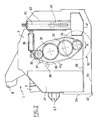
- the toothed wheel 22 is the output wheel of a transmission box 30 which includes a set of pinions 31, 32 and an input pinion 33.
- the pinion 33 is coupled in rotation to a tree symbolized by the axis 34 of Figure 1 itself connected to the output shaft 11 of the gearbox 10 by a cardan system 35 shown symbolically.
- the cardan system 35 is housed in a housing located along the inner face of the sidewall 3 of frame 1. The cardan system 35 allows movement of the shaft 34 parallel to itself.
- the transmission box 30 is pivotally mounted around the axis 16 of the wheel 22. It is also immobilized in angular position around this axis 16 by an elastic return system 36 which holds it in the position shown in Figures 1 and 2 under a determined effort thus generating around axis 16 a holding torque of the housing 30 also determined.
- the recall system 36 can be constituted by a spring device associated with a shock absorber hydraulic, an oleopneumatic device, preferably adjustable, or a simple block of rubber.
- the housing 30 tends to pivot around axis 16 in the opposite direction clockwise, which is possible thanks to the light 37 formed in the sidewall 3 for the passage of axis 34.
- This pivoting will be achieved if the effort of normal recall of the recall system 36 is defeated and therefore allows a sudden cashing on the rotor.
- the pivoting of the housing 30 can be detected by a detector or sensor 38 intended to output a signal which can be used for example uncoupling, by means of a clutch device provided for this purpose, the output shaft 11 of the PTO 9 upstream of it.
- the sensor 38 can also be housed inside the return member 36 doing so a whole with it that it is possible to adjust prior to the final assembly of the mill.
- the adjustment of the penetration depth of the rotor in the ground can be ensured by a pair of soles such as those 41 shown in Figures 1 and 2 attached to each upright or vertical leg 42 whose position is adjustable in a sleeve 43, 44 carried by the outer surface of each of the sides 2 and 3.
- the height adjustment of the soles 41 can be ensured for example as shown in Figure 2, by a screw-nut system, the sleeves 43 and 44 carrying a screws 45, 46 which can rotate inside of them while the corresponding amount 42 is formed into a nut while being immobilized in rotation, the sleeves 43 being for example of square section.
- This setting can be powered by any known means and maneuver in rotation of the two screws 45, 46 can be synchronized.
- deflectors 47, 48 which form elements to drive out the stones on the sides of the crusher and protect in particular the transmission box 30.
- the motorization of the rotor 12 is made on one side of the mill.
- FIG. 2 there is shown in 30a a housing identical to box 30 which contains the same set of sprockets extending between a wheel, such as that propped up 22 on a rotor drive shaft that the latter has at its other end like that 20 of the Figure 3 and a toothed wheel such as 33 coupled to second transmission output shaft of the gearbox reference 9.
- Side 2 also has a light such than that of flank 3.
- housing 30a does not cooperate with any recall system such as that 36. Its function, because of its ability to pivot, lies in taking into account angular offsets necessarily existing between the homologous elements of the two transmission branches due to mounting and manufacturing tolerances. This arrangement eliminates a device differential transmission between the two branches.
Landscapes
- Life Sciences & Earth Sciences (AREA)
- Engineering & Computer Science (AREA)
- Mechanical Engineering (AREA)
- Soil Sciences (AREA)
- Environmental Sciences (AREA)
- Crushing And Pulverization Processes (AREA)
Applications Claiming Priority (2)
| Application Number | Priority Date | Filing Date | Title |
|---|---|---|---|
| FR9910357 | 1999-08-10 | ||
| FR9910357A FR2797404B1 (fr) | 1999-08-10 | 1999-08-10 | Broyeurs de pierres mobiles |
Publications (1)
| Publication Number | Publication Date |
|---|---|
| EP1075784A1 true EP1075784A1 (de) | 2001-02-14 |
Family
ID=9549047
Family Applications (1)
| Application Number | Title | Priority Date | Filing Date |
|---|---|---|---|
| EP00402245A Withdrawn EP1075784A1 (de) | 1999-08-10 | 2000-08-08 | Verfahrbarer Steinbrecher |
Country Status (2)
| Country | Link |
|---|---|
| EP (1) | EP1075784A1 (de) |
| FR (1) | FR2797404B1 (de) |
Citations (5)
| Publication number | Priority date | Publication date | Assignee | Title |
|---|---|---|---|---|
| US2795176A (en) * | 1955-09-29 | 1957-06-11 | Raymond L O'hara | Pulverizing machine |
| WO1989003635A1 (fr) * | 1987-10-23 | 1989-05-05 | Kabushiki Kaisha Komatsu Seisakusho | Concasseur autopropulse |
| US4903780A (en) * | 1986-07-11 | 1990-02-27 | Elda Barbieri | Mobile, self-propelled crushing machine |
| FR2662899A1 (fr) * | 1990-06-06 | 1991-12-13 | Belin Jean Pierre | Capot diffuseur pour broyeur de pierres. |
| DE4317288A1 (de) * | 1993-05-25 | 1994-12-01 | Thyssen Industrie | Zerkleinerungsvorrichtung für insbesondere Schrott, Industrie- und/oder Hausmüll |
Family Cites Families (1)
| Publication number | Priority date | Publication date | Assignee | Title |
|---|---|---|---|---|
| US2856134A (en) * | 1955-09-06 | 1958-10-14 | Tormey James Silvester | Combination soil shredder and horticultural hammer mill |
-
1999
- 1999-08-10 FR FR9910357A patent/FR2797404B1/fr not_active Expired - Lifetime
-
2000
- 2000-08-08 EP EP00402245A patent/EP1075784A1/de not_active Withdrawn
Patent Citations (5)
| Publication number | Priority date | Publication date | Assignee | Title |
|---|---|---|---|---|
| US2795176A (en) * | 1955-09-29 | 1957-06-11 | Raymond L O'hara | Pulverizing machine |
| US4903780A (en) * | 1986-07-11 | 1990-02-27 | Elda Barbieri | Mobile, self-propelled crushing machine |
| WO1989003635A1 (fr) * | 1987-10-23 | 1989-05-05 | Kabushiki Kaisha Komatsu Seisakusho | Concasseur autopropulse |
| FR2662899A1 (fr) * | 1990-06-06 | 1991-12-13 | Belin Jean Pierre | Capot diffuseur pour broyeur de pierres. |
| DE4317288A1 (de) * | 1993-05-25 | 1994-12-01 | Thyssen Industrie | Zerkleinerungsvorrichtung für insbesondere Schrott, Industrie- und/oder Hausmüll |
Also Published As
| Publication number | Publication date |
|---|---|
| FR2797404B1 (fr) | 2002-09-06 |
| FR2797404A1 (fr) | 2001-02-16 |
Similar Documents
| Publication | Publication Date | Title |
|---|---|---|
| CA2107020C (fr) | Faucheuse avec un entrainement perfectionne des rouleaux de traitement | |
| EP0356358B1 (de) | Mähmaschine mit verbessertem Rahmen | |
| EP0337909B1 (de) | Direktangetriebene Mähmaschine | |
| EP0175629B1 (de) | Kreiselmäher | |
| EP0124462A1 (de) | Landwirtschaftliche Maschine mit Übertragungsvorrichtung | |
| EP0086171A1 (de) | Scheibenmäher mit Antriebswelle und Verfahren zum Herstellen dieser Welle | |
| FR2563686A1 (fr) | Faucheuse | |
| FR2976154A1 (fr) | Extracteur de pierres des sols, principalement agricoles. | |
| FR2589669A1 (fr) | Faucheuse rotative | |
| FR2590441A2 (fr) | Faucheuse perfectionnee | |
| EP1169901B1 (de) | Bodenbearbeitungsmaschine | |
| EP1776856B1 (de) | Vegetations-Mähvorrichtung | |
| FR2458207A1 (fr) | Dispositif a lames tournantes pour motofaucheuses | |
| FR2642260A1 (fr) | Faucheuse | |
| FR2534213A1 (fr) | Tracteur ou vehicule similaire muni de roues motrices et directrices commandees par des fusees | |
| EP1434476A1 (de) | Landmaschine, insbesondere kreiselmäher, mit verbesserter häckselvorrichtung | |
| FR2907637A1 (fr) | "dispositif debroussailleur-broyeur de vegetaux" | |
| FR2552616A1 (fr) | Machine pour travailler le sol, munie d'un moteur | |
| EP1075784A1 (de) | Verfahrbarer Steinbrecher | |
| FR2521389A1 (fr) | Dispositif de coupe pour faucheuse | |
| FR2948850A1 (fr) | Equipement de coupe et de broyage de vegetaux, pour vehicule tracteur | |
| EP0680688A1 (de) | Heuwerbungsmaschine, insbesondere ein Schwader für Futter | |
| FR2733115A1 (fr) | Dispositif debroussailleur-broyeur de vegetaux | |
| FR3016493A1 (fr) | Equipement pour la coupe et/ou le broyage de vegetaux | |
| FR2686031A1 (fr) | Rotor a couteaux tournants, et machine de coupe de vegetaux, notamment broyeur forestier, equipee d'au moins un tel rotor. |
Legal Events
| Date | Code | Title | Description |
|---|---|---|---|
| PUAI | Public reference made under article 153(3) epc to a published international application that has entered the european phase |
Free format text: ORIGINAL CODE: 0009012 |
|
| AK | Designated contracting states |
Kind code of ref document: A1 Designated state(s): AT BE CH CY DE DK ES FI FR GB GR IE IT LI LU MC NL PT SE |
|
| AX | Request for extension of the european patent |
Free format text: AL;LT;LV;MK;RO;SI |
|
| 17P | Request for examination filed |
Effective date: 20010613 |
|
| AKX | Designation fees paid |
Free format text: AT BE CH CY DE DK ES FI FR GB GR IE IT LI LU MC NL PT SE |
|
| GRAP | Despatch of communication of intention to grant a patent |
Free format text: ORIGINAL CODE: EPIDOSNIGR1 |
|
| STAA | Information on the status of an ep patent application or granted ep patent |
Free format text: STATUS: THE APPLICATION IS DEEMED TO BE WITHDRAWN |
|
| 18D | Application deemed to be withdrawn |
Effective date: 20070627 |