EP1075865B1 - Vorrichtung zur Verwendung in einer Abwasserbehandlungsanlage - Google Patents
Vorrichtung zur Verwendung in einer Abwasserbehandlungsanlage Download PDFInfo
- Publication number
- EP1075865B1 EP1075865B1 EP00306860A EP00306860A EP1075865B1 EP 1075865 B1 EP1075865 B1 EP 1075865B1 EP 00306860 A EP00306860 A EP 00306860A EP 00306860 A EP00306860 A EP 00306860A EP 1075865 B1 EP1075865 B1 EP 1075865B1
- Authority
- EP
- European Patent Office
- Prior art keywords
- flow
- sewage
- tank
- screen
- settlement
- Prior art date
- Legal status (The legal status is an assumption and is not a legal conclusion. Google has not performed a legal analysis and makes no representation as to the accuracy of the status listed.)
- Expired - Lifetime
Links
Images

Classifications
-
- E—FIXED CONSTRUCTIONS
- E02—HYDRAULIC ENGINEERING; FOUNDATIONS; SOIL SHIFTING
- E02B—HYDRAULIC ENGINEERING
- E02B8/00—Details of barrages or weirs ; Energy dissipating devices carried by lock or dry-dock gates
- E02B8/02—Sediment base gates; Sand sluices; Structures for retaining arresting waterborne material
- E02B8/023—Arresting devices for waterborne materials
- E02B8/026—Cleaning devices
-
- B—PERFORMING OPERATIONS; TRANSPORTING
- B01—PHYSICAL OR CHEMICAL PROCESSES OR APPARATUS IN GENERAL
- B01D—SEPARATION
- B01D21/00—Separation of suspended solid particles from liquids by sedimentation
- B01D21/0012—Settling tanks making use of filters, e.g. by floating layers of particulate material
-
- B—PERFORMING OPERATIONS; TRANSPORTING
- B01—PHYSICAL OR CHEMICAL PROCESSES OR APPARATUS IN GENERAL
- B01D—SEPARATION
- B01D21/00—Separation of suspended solid particles from liquids by sedimentation
- B01D21/24—Feed or discharge mechanisms for settling tanks
- B01D21/2405—Feed mechanisms for settling tanks
-
- B—PERFORMING OPERATIONS; TRANSPORTING
- B01—PHYSICAL OR CHEMICAL PROCESSES OR APPARATUS IN GENERAL
- B01D—SEPARATION
- B01D21/00—Separation of suspended solid particles from liquids by sedimentation
- B01D21/24—Feed or discharge mechanisms for settling tanks
- B01D21/245—Discharge mechanisms for the sediments
Definitions
- the invention relates to an apparatus for use in a sewage treatment plant.
- Effluent flow entering a sewage treatment plant contains solid materials, such as rags, paper, polythene and other plastic sheeting, and the like, which cannot be processed by the treatment plant.
- Solids can be removed from the flow by screens or sieves which capture the solids. The screens or sieves are then periodically or continuously operated for cleaning to remove the captured solids, commonly referred to as screenings, for disposal.
- screening apparatus known in the art is the "continuous-belt screen" which includes a continuous driven belt screen presenting a continuous, moving screening area to the input sewage flow to effect removal of screenings within the sewage flow.
- the belt screen removes any solid materials carried by the input sewage flow whilst permitting the liquid phase of the sewage to flow onwards to the subsequent processing stages of the treatment plant.
- EP-A-0728512 discloses one form of such a continuous belt screen which is disposed in a flow channel leading to a sewage treatment plant.
- US-A-1748151 discloses in combination a rotating screen and an endless conveyor in a sewage disposal pit. Solid material picked up by the conveyor is scraped off at a level above and outside the pit, whilst the screen ensures that only clear liquid will enter the pit chamber and the outlet therefrom.
- British Patent Application 2039769 discloses a suspension filtration unit in which a liquid with suspended solids is fed into a tank containing one or more included belt filters.
- the apparatus of this disclosure is structurally similar to the present invention it is completely unsuitable for use in sewage treatment as the flow is not screened to remove screenings and the tank is not designed for grit settlement.
- the filter belts would become clogged with faecal material undesirably removed from the flow, it being the intention in sewage treatment that a screened and de-gritted flow containing a suspension of faecal and other organic material should be delivered to later treatment stages for processing.
- the head loss i.e. the difference in sewage flow level between the flow upstream of the screening apparatus and the flow downstream of the screening apparatus
- the head loss is determined by the screening area which is presented to the input flow; the smaller the screening area presented to the input flow, the greater the head loss and the less efficient the apparatus at higher flow rates.
- the continuous belt screen 6 is located in an inlet channel 10 which delivers the sewage flow 12 to the inlet stage, or inlet works, of the sewage treatment plant where the inlet sewage flow is screened. Following the inlet stage, screened sewage is passed through a grit removal facility, where grit and other small stones are removed from the sewage flow. The screened sewage is then delivered to the subsequent sewage processing stages.
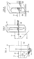
- the depth of the inlet channel 10 is limited, only a limited screening area is presented to the sewage flow 12 and the head loss, represented by D 2 , is significant. Such arrangements therefore tend to be inefficient, especially at higher flow rates.
- an apparatus for use in a sewage treatment plant for removal from a sewage flow of materials such as grits, screenings, stones and rocks
- the apparatus including a grit settlement tank arranged to provide sufficient residence time for the flow to enable grit to settle from the flow, an inlet channel for delivering the flow in use to the tank, and a screen arrangement having a continuous belt screen, the apparatus being characterised in that said screen arrangement is positioned in said settlement tank to receive and screen the flow from said channel as it enters said tank, and said screen arrangement being such as to permit grit to pass therethrough with the flow into said tank for settlement but to intercept and remove from the flow, upstream of the settlement tank, stones, rocks, and screenings carried in the flow to prevent them entering the tank with the remainder of said flow.
- the apparatus may be used in an inlet stage, or inlet works, of a sewage treatment plant.
- the apparatus provides the advantage that, as the settlement thank has a large volume and as the screen arrangement is arranged within the settlement tank, the screening area presented to the input sewage flow is greatly increased.
- the head loss can be reduced, or substantially eliminated, compared to known arrangements in which the screen arrangement is arranged within the inlet channel. In this way, the efficiency of the apparatus can be improved and the cost of installation can be reduced.
- the settlement thank may comprise an inlet chamber, the input sewage flow being delivered to the inlet chamber by the inlet chamber.
- the inlet chamber may deliver the sewage flow directly to the screen arrangement or may deliver the sewage flow to the screen arrangement through a transition channel.
- the floor of the inlet chamber may be raised above the floor of the settlement tank.
- the floor of the inlet chamber may be provided with a recess or depression for retaining stones or rocks contained within the sewage flow prior to delivery of the flow to the screen arrangement.
- the floor of the transition channel may be raised above the floor of the settlement tank, a recess or depression being provided in the floor of the transition channel for retaining stones or rocks contained within the sewage flow.
- Means may be provided for removing stones or rocks retained upstream of the screen arrangement. Removal of stones or rocks from the sewage flow prevents damage being caused to the screen arrangement and any screenings washing apparatus located downstream of the screen arrangement. Means may also be provided for isolating the screen arrangement from the sewage flow. Such means may comprise a stop-gate.
- the apparatus may further comprise a removal apparatus for removing settled products, such as grit and small stones, from the settlement tank.
- the removal apparatus may take the form of a pumping apparatus.
- the apparatus may also include a separation apparatus for separating products of different type which are removed from the settlement region.
- the settlement apparatus may thus separate grit and small stones removed from the settlement tank from other products, such as vegetable products and other relatively fine particles of solid sewage materials, which may settle in the settlement tank.
- the apparatus may further comprise a washing apparatus for washing screenings removed from the sewage flow by the screen arrangement.
- the settlement tank may be provided with an outlet weir, over which screened sewage is discharged to an outlet chamber, the walls of the outlet chamber and the settlement tank being formed from the same housing.
- the sewage discharged over the weir is de-gritted.
- the settlement tank and the outlet chamber may be covered, and wherein a washing apparatus is present, it is supported on or above the covering. Thus, a reduced installation space is required to accommodate the complete apparatus.
- the means for removing rocks or stones retained upstream of the screen arrangement may transport said stones or rocks to the settlement tank for extraction therefrom.
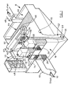
- a sewage processing apparatus includes an inlet channel 10 for delivering a sewage flow, represented by arrow 12, to an inlet chamber 14 forming part of a main settlement tank 16, commonly referred to as the "grit settlement tank".
- the inlet channel 10 forms a bridge structure such that the floor level of the inlet channel 10 is raised above the floor level of the grit settlement tank 16, as can be seen most clearly in Figure 1.
- the apparatus 8 also includes first and second screen arrangements 18,20, sewage flow being delivered to the screen arrangements 18,20 through respective transition channels 22,24 which communicate with the inlet chamber 14.
- Each of the transition channels 22,24 is provided with a respective stop-gate 26,28, the stop-gates being operable independently between a closed position, in which sewage flow within the inlet chamber 14 is isolated from the respective transition channel 22,24, and an open position in which sewage flow within the inlet chamber 14 is able to flow into the respective transition channel 22,24.
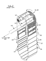
- each of the screen arrangements 18,20 may be of a conventional "belt-screen" type, including a number of screen panels 30, the screen panels 30 being connected so as to form a continuous loop providing a belt screen 32, each screen panel 30 being connected to the adjacent screen panels, one on each side, by hinging means 34.
- the hinging means 34 may be in the form of a series of interdigitated lugs (not shown in detail), arranged along the edge of each panel 30, in which a retaining pin is received, the retaining pin passing through the lugs on adjacent panels 30 to secure adjacent panels together.
- the continuous belt screen 32 is driven by a drive mechanism (not shown in the figures) such that the screen panels 30 are conveyed upwardly on one side of the arrangement 18,20 and downwardly on the other side in a direction as indicated by arrows 36.
- the screen panels 30 form a continuous belt, driven by the drive mechanism, which presents a substantially continuous, moving screening area to the input sewage flow.
- the screen panels 30 are formed from sheets of perforated metal, the perforations 38 of which enable sewage in the liquid phase to pass through the panels 30 to the downstream part of the grit settlement tank 16 and onwards to the subsequent processing stages of the treatment plant.
- the perforations 38 are such that solid materials in the sewage flow, having a greater dimension than the perforations, are captured.
- the liquid phase of the sewage is therefore passed out from the screen arrangement 18,20, through the continuous belt screen 32 on each side and through a part at the base, whilst the screenings are retained.
- the passage of liquid sewage through the screen arrangements is indicated by the arrows 12a, as shown in Figure 2.
- Hooks or prongs 40 are arranged internally on the belt screen 32 at spaced locations around the loop.
- the hooks 40 are usually located between adjoining screen panels 30 and serve to capture the screenings contained within the sewage flow as the belt screen 32 passes continuously therethrough.
- the screenings may be removed from the belt screen 32 by means of a rotary brush 42 housed within the head space of the screen arrangement 18,20 as they are conveyed through the head space past the rotary brush 42.
- Each screen arrangement 18,20 also includes a hopper 44 into which captured screenings, which will be contaminated by faecal materials, are dislodged from the belt screen 32 by the rotary brush 42.
- the screenings removed by the rotary brush 42 are then discharged from the hopper 44 into a launder 46.
- the screen arrangements 18,20 share a common launder 46 into which screenings removed from the flow by both of the screen arrangements 18,20 are discharged.
- the launder 46 carries the screenings to a washing apparatus 48.
- the washing apparatus 48 may be of the type described in EP 0 557 030, which includes a washing tank into which the screenings are introduced along with aqueous liquid.
- a washing compound may also be introduced into the washing tank to aid washing of the screenings.
- a rotating impeller generates turbulence within the aqueous liquid in the tank, resulting in a break down of the faecal contaminants.
- the washed and compacted screenings are then discharged from the apparatus 48 through an outlet chute 50 which delivers the screenings into an incinerator or to a vehicle for carrying the screenings away from the treatment works. It will be appreciated, however, that alternative means of washing the screenings may be provided instead of the washing apparatus 48 described above.
- First and second suction pumps, 56,58 serve to pump these small stones and grit within the settlement region 52 through vertically extending pipes 58 (only one of which is shown in Figure 1) to a main pipe 60 which delivers the materials to a separation apparatus 62.
- the separation apparatus 62 separates different types of product removed from the settlement region 52.
- the separation apparatus 62 may be arranged to separates grit and small stones pumped through the pipes 58,60 from other materials, such as rags, paper and other fibrous materials, which also settle in the settlement region 52.
- the apparatus 62 may conveniently be of the type described GB 2261612.
- the apparatus includes means for washing the grit and small stones, the washed materials being discharged through an outlet channel 63 for safe removal from the site.
- the rags, paper and other fibrous materials separated to the inlet channel 14 where they are re-introduced to the sewage flow to be passed through the screen arrangements 18,20.
- the screened sewage flow, including any grease materials, is then passed over an outlet weir 64 into an outlet chamber 66, the screened sewage flow being discharged from the outlet chamber 66 through an outlet channel 68 to the subsequent processing stages of the sewage treatment plant.
- a stone collection region 72 may be formed in the transition channel 22, larger stones or rocks 74, or other larger, solid materials, which are carried by the sewage flow settling in the region 72 under the effect of gravity. The retention of large stones or rocks in the collection region 72 prevents such materials causing any damage to the screen arrangements 18,20 downstream of the collection region 72.
- a valve arrangement 76 (as indicated in Figure 2) may also be provided, opening of the valve arrangement 76 permitting stones or rocks retained within the collection region 72 to be delivered through an outlet pipe to a collection chamber 59 at the base of the grit settlement tank 16 for removal from the site.
- the valve arrangement 76 associated with the collection region 72 may be operated manually or automatically.
- the stone collection region may be provided in the inlet chamber 14, the inlet chamber 14 being provided with an appropriate valve arrangement to effect removal of stones and rocks collected within the stone collection region.
- the inlet chamber 14 may deliver the sewage flow directly to the screen arrangements 18,20.
- the stone collection region is conveniently formed in the inlet chamber 14.
- the floor of the inlet channel 10 may be provided with a recess or depression (not shown) which provides a stone collection region for stones, rocks or other larger, solid materials carried by the sewage flow within the inlet channel 10.
- the inlet channel 10 may also be provided with a valve arrangement to permit collected stones or rocks to be delivered through an outlet pipe into the collection chamber for removal from the site.
- a valve arrangement to permit collected stones or rocks to be delivered through an outlet pipe into the collection chamber for removal from the site.
- the grit settlement tank 16 has considerably greater depth than the inlet channel 10.
- the head loss as indicated by D 1 , can therefore be reduced significantly compared to conventional arrangements, in which the screen arrangement is located within the inlet channel.
- D 1 the head loss
- D 2 the head loss
- the present invention also provides the advantage that the stone collection region 72, upstream of the screen arrangement 18,20, can be provided within the inlet chamber 14 or the transition channels 22,24.
- a recess in the floor of the inlet channel may be used to provide a means of retaining stones or rocks.
- this form of stone-trap facility is difficult to access and cannot be maintained easily.
- the recess will eventually cease to provide an adequate stone-trapping function.
- the grit settlement tank 16 and the outlet chamber 66 are covered by a floor covering, preferably made from steel sheeting, to enable operating personal to access different parts of the apparatus 8 for maintenance or operating purposes.
- the separation apparatus 62 and the washing apparatus 48 are supported on or above the floor covering.
- the walls of the grit settlement tank 16 and the outlet chamber 66 are formed from the same housing, and as the washing apparatus 48 and the separation apparatus 62 are arranged above the tank 16, a reduced installation space is required to accommodate the complete apparatus 8.
- the periphery 78 of the tank 16 may be provided with a hand rail for safety purposes.
- the tank 16, including the inlet chamber 14, the inlet channel 10, the outlet chamber 66, the outlet channel 68 are preferably formed from steel.
- Other parts of the apparatus 8 may also be formed from steel, so as to simplify manufacture of the complete apparatus and reduce cost.
- the apparatus 8 may also include a grease removal apparatus (not shown in the accompanying figures) located downstream of the screen arrangements 18,20, to effect removal of grease materials present within the sewage flow prior to discharge of the flow through the outlet channel 68.
- the grease removal apparatus may include a tank region, forming part of the outlet chamber 66, which is provided with a diffused air system for generating a turbulence effect within the sewage flow, thereby causing grease materials present in the screened sewage flow to rise to the surface of the flow.
- the grease removal apparatus includes a scraper board or plate for removing grease on the surface of the sewage flow and for discharging the removed products to a disposal point.
- the apparatus 8 can be handled as a unit.
- the apparatus 8 may be manufactured and constructed in a factory and then transported to the designated installation site.
- the apparatus 8 may be manufactured with any one or more of the various parts of the apparatus hereinbefore described, such as the washing apparatus 48, the separation apparatus 62, the grease removal apparatus or the grit pumping system, depending on the requirements of the customer.
- the apparatus may take the form of a relatively large-scale installation comprising a permanent concrete grit settlement tank and other permanent concrete structures, in which case it may be preferable to assemble the apparatus at the installation site.
Landscapes
- Engineering & Computer Science (AREA)
- General Engineering & Computer Science (AREA)
- Mechanical Engineering (AREA)
- Civil Engineering (AREA)
- Structural Engineering (AREA)
- Chemical & Material Sciences (AREA)
- Chemical Kinetics & Catalysis (AREA)
- Separation Of Solids By Using Liquids Or Pneumatic Power (AREA)
- Sewage (AREA)
Claims (17)
- Vorrichtung zur Verwendung in einer Abwasserbehandlungsanlage, zum Entfernen von Materialien, wie beispielsweise Sanden, Siebrückständen, Geröll und Gestein, aus einem Abwasserstrom, wobei die Vorrichtung (8) einen Sandabsetzbehälter (16), angeordnet, um eine ausreichende Verweilzeit für den Strom zu gewährleisten, um zu ermöglichen, daß sich Sand aus dem Strom absetzt, einen Einlaßkanal (10), um den Strom bei Anwendung dem Behälter (16) zuzuführen, und eine Siebanordnung (18, 20), die ein Endlosbandsieb hat, einschließt, wobei die Vorrichtung dadurch gekennzeichnet ist, daß die Siebanordnung in dem Absetzbehälter (16) angeordnet ist, um den Strom aus dem Kanal (10) aufzunehmen und zu sieben, wenn er in den Behälter eintritt, und die Siebanordnung derart ist, daß sie ermöglicht, daß Sand mit dem Strom in den Behälter zum Absetzen durch sie hindurchgeht, sie aber stromaufwärts von dem Absetzbehälter (16) Geröll, Gestein und Siebrückstände, die in dem Strom mitgerissen werden, auffängt und aus dem Strom entfernt, um zu verhindern, daß sie mit dem Rest des Stroms in den Behälter eintreten.
- Vorrichtung nach Anspruch 1, dadurch gekennzeichnet, daß der Absetzbehälter (16) ferner eine Einlaßkammer (14) umfaßt, wobei der eingelassene Abwasserstrom der Einlaßkammer (14) durch den Einlaßkanal (10) zugeführt wird.
- Vorrichtung nach Anspruch 2, dadurch gekennzeichnet, daß die Einlaßkammer (14) angeordnet ist, um den Abwasserstrom unmittelbar der Siebanordnung (18, 20) zuzuführen.
- Vorrichtung nach Anspruch 2, dadurch gekennzeichnet, daß die Einlaßkammer (14) angeordnet ist, um den Abwasserstrom der Siebanordnung (18, 20) durch einen Übergangskanal (22, 24) zuzuführen.
- Vorrichtung nach einem der Ansprüche 2 bis 4, dadurch gekennzeichnet, daß der Boden der Einlaßkammer (14) über den Boden des Absetzbehälters (16) angehoben ist.
- Vorrichtung nach Anspruch 5, dadurch gekennzeichnet, daß der Boden der Einlaßkammer (14) mit einer Aussparung oder Vertiefung versehen ist, um Geröll oder Gestein, die innerhalb des Abwasserstroms enthalten sind, vor dem Zuführen des Stroms zu der Siebanordnung (18, 20) zurückzuhalten.
- Vorrichtung nach Anspruch 4, dadurch gekennzeichnet, daß der Boden des Übergangskanals (22, 24) über den Boden des Absetzbehälters (16) angehoben ist, wobei im Boden des Übergangskanals (22, 24) eine Aussparung oder Vertiefung bereitgestellt wird, um Geröll oder Gestein, die innerhalb des Abwasserstroms enthalten sind, zurückzuhalten.
- Vorrichtung nach Anspruch 6 oder Anspruch 7, ferner gekennzeichnet durch Mittel zum Entfernen von Geröll oder Gestein, die stromaufwärts von der Siebanordnung zurückgehalten werden.
- Vorrichtung nach einem der Ansprüche 1 bis 7, gekennzeichnet durch Mittel (26, 28) zum Isolieren der Siebanordnung (18, 20) von dem Abwasserstrom.
- Vorrichtung nach Anspruch 9, dadurch gekennzeichnet, daß das Mittel zum Isolieren der Siebanordnung (18, 20) von dem Abwasserstrom einen Balkendamm (26, 28) umfaßt.
- Vorrichtung nach einem der Ansprüche 1 bis 10, ferner gekennzeichnet durch eine Entfernungsvorrichtung zum Entfernen von Absetzprodukten aus dem Absetzbehälter (16).
- Vorrichtung nach Anspruch 11, dadurch gekennzeichnet, daß die Entfernungsvorrichtung die Form einer Pumpvorrichtung annimmt.
- Vorrichtung nach Anspruch 11 oder Anspruch 12, ferner gekennzeichnet durch eine Abscheidevorrichtung (62) zum Abscheiden von Produkten unterschiedlicher Art, die aus dem Absetzbereich (52) entfernt werden.
- Vorrichtung nach einem der Ansprüche 1 bis 13, ferner gekennzeichnet durch eine Waschvorrichtung zum Waschen von Siebrückständen, die durch die Siebanordnung aus dem Abwasserstrom entfernt werden.
- Vorrichtung nach einem der Ansprüche 1 bis 14, dadurch gekennzeichnet, daß der Absetzbehälter (16) mit einem Auslaßwehr (64) versehen ist, über das gesiebtes Abwasser zu einer Auslaßkammer (66) abgelassen wird, wobei die Wände der Auslaßkammer (66) und des Absetzbehälters (16) aus dem gleichen Gehäuse hergestellt sind.
- Vorrichtung nach Anspruch 15, dadurch gekennzeichnet, daß der Absetzbehälter (16) und die Auslaßkammer (66) abgedeckt sind, und wobei eine Waschvorrichtung zum Waschen von Siebrückständen, die durch die Siebanordnung (18, 20) aus dem Abwasserstrom entfernt werden, an oder über der Abdeckung getragen wird.
- Vorrichtung nach Anspruch 8, dadurch gekennzeichnet, daß das Mittel das Geröll oder das Gestein zum Entfernen aus demselben zu dem Absetzbehälter (16) befördert.
Applications Claiming Priority (2)
| Application Number | Priority Date | Filing Date | Title |
|---|---|---|---|
| GB9919183 | 1999-08-13 | ||
| GBGB9919183.5A GB9919183D0 (en) | 1999-08-13 | 1999-08-13 | Apparatus for use in a sewage treatment plant |
Publications (2)
| Publication Number | Publication Date |
|---|---|
| EP1075865A1 EP1075865A1 (de) | 2001-02-14 |
| EP1075865B1 true EP1075865B1 (de) | 2006-07-19 |
Family
ID=10859133
Family Applications (1)
| Application Number | Title | Priority Date | Filing Date |
|---|---|---|---|
| EP00306860A Expired - Lifetime EP1075865B1 (de) | 1999-08-13 | 2000-08-10 | Vorrichtung zur Verwendung in einer Abwasserbehandlungsanlage |
Country Status (4)
| Country | Link |
|---|---|
| US (1) | US6365045B1 (de) |
| EP (1) | EP1075865B1 (de) |
| AU (1) | AU5197300A (de) |
| GB (1) | GB9919183D0 (de) |
Families Citing this family (5)
| Publication number | Priority date | Publication date | Assignee | Title |
|---|---|---|---|---|
| GB2403438B (en) * | 2003-03-06 | 2005-07-27 | Three Star Enviromental Ltd | Screening apparatus |
| US20050109687A1 (en) * | 2003-11-25 | 2005-05-26 | Su-Ching Su | Treating apparatus for organic waste |
| GB201203092D0 (en) | 2012-02-22 | 2012-04-04 | Anglian Water Services Ltd | Screen |
| US9334178B2 (en) | 2012-11-08 | 2016-05-10 | Smith & Loveless Inc. | Vortex-type grit chamber |
| CN114134987B (zh) * | 2021-12-29 | 2022-09-06 | 上海艺迈实业有限公司 | 一种一体化预制泵站 |
Citations (2)
| Publication number | Priority date | Publication date | Assignee | Title |
|---|---|---|---|---|
| US1748151A (en) * | 1930-02-25 | steeling | ||
| EP0728512A2 (de) * | 1995-02-21 | 1996-08-28 | JONES & ATTWOOD LIMITED | Sieb |
Family Cites Families (16)
| Publication number | Priority date | Publication date | Assignee | Title |
|---|---|---|---|---|
| US1820976A (en) * | 1927-10-08 | 1931-09-01 | Imhoff Karl | Sewage treatment |
| US2267086A (en) * | 1937-07-22 | 1941-12-23 | William J Donohue | Filtering method and apparatus |
| US3754661A (en) * | 1971-04-15 | 1973-08-28 | Fmc Corp | Apparatus for clarifying liquid |
| FI56319C (fi) * | 1979-01-22 | 1980-01-10 | Partek Ab | Anordning foer separering av suspenderade fasta partiklar ur en vaetskestroem |
| US4421647A (en) * | 1982-06-28 | 1983-12-20 | Barnes Drill Co. | Filter with indexable filter web |
| SE458827B (sv) * | 1986-12-15 | 1989-05-16 | Persson Per Oskar Ingf Ab | Vaetskefilter |
| US4971693A (en) * | 1989-09-07 | 1990-11-20 | 501 Kabushiki Kaisha Iseki Kaihatsu Koki | Muddy water processing apparatus |
| DE9104551U1 (de) * | 1991-04-13 | 1991-06-06 | Bormet, Horst, 6108 Weiterstadt | Siebrechen |
| GB9123952D0 (en) * | 1991-11-12 | 1992-01-02 | Jones & Attwood Ltd | Separation of solids from liquids |
| CA2089400C (en) * | 1992-02-15 | 2002-08-13 | John Cedric Bache | Washing apparatus |
| DE9204019U1 (de) * | 1992-03-25 | 1992-09-10 | Stahlform Stahl- u. Metallbau GmbH, 86971 Peiting | Reinigungsvorrichtung |
| US5256290A (en) * | 1992-04-15 | 1993-10-26 | Monlan, Incorporated | Coolant filtration unit with sludge dryer |
| JP3004556B2 (ja) * | 1994-03-03 | 2000-01-31 | 株式会社シスト | 分別濾過方法及び分別濾過装置 |
| US5770092A (en) * | 1994-06-15 | 1998-06-23 | Solar Dynamics Ltd. | Apparatus and method for purifying water |
| DE29519626U1 (de) * | 1995-12-11 | 1996-01-25 | Deckel Maho GmbH, 87459 Pfronten | Reinigungsvorrichtung |
| US5827425A (en) * | 1995-12-21 | 1998-10-27 | Mckinnon; Nick | Grease recovery system and methods |
-
1999
- 1999-08-13 GB GBGB9919183.5A patent/GB9919183D0/en not_active Ceased
-
2000
- 2000-08-10 EP EP00306860A patent/EP1075865B1/de not_active Expired - Lifetime
- 2000-08-11 AU AU51973/00A patent/AU5197300A/en not_active Abandoned
- 2000-08-14 US US09/638,818 patent/US6365045B1/en not_active Expired - Fee Related
Patent Citations (2)
| Publication number | Priority date | Publication date | Assignee | Title |
|---|---|---|---|---|
| US1748151A (en) * | 1930-02-25 | steeling | ||
| EP0728512A2 (de) * | 1995-02-21 | 1996-08-28 | JONES & ATTWOOD LIMITED | Sieb |
Also Published As
| Publication number | Publication date |
|---|---|
| US6365045B1 (en) | 2002-04-02 |
| GB9919183D0 (en) | 1999-10-20 |
| EP1075865A1 (de) | 2001-02-14 |
| AU5197300A (en) | 2001-02-15 |
Similar Documents
| Publication | Publication Date | Title |
|---|---|---|
| US8092674B2 (en) | Traveling band screen machine | |
| US5730886A (en) | Continuous self-cleaning filtration unit | |
| AU2017203791A1 (en) | Rotary interstage screen apparatus | |
| KR102118685B1 (ko) | 고압용 오배수 펌프시스템 | |
| EP1075865B1 (de) | Vorrichtung zur Verwendung in einer Abwasserbehandlungsanlage | |
| EP1039055B1 (de) | Siebvorrichtung für Abwasser | |
| AU728143B2 (en) | Portable water recycler | |
| US6997328B2 (en) | Grit removal assemblies | |
| CN214634648U (zh) | 粗、细格栅一体机 | |
| US5695649A (en) | Method and apparatus for removing sludge from an enclosure | |
| KR102141076B1 (ko) | 무빙스크린을 이용한 종합처리기 | |
| KR102601272B1 (ko) | 협잡물의 이송이 용이한 스크린 장치 및 스크린 장치의 이상동작 대응 방법 | |
| JP2003094069A (ja) | 汚水処理方法及び汚水処理装置 | |
| CN214233144U (zh) | 防堵塞排砂装置及污水净化系统 | |
| CN107261634A (zh) | 一种辊式污水污泥高效分离处理设备 | |
| RU2151627C1 (ru) | Установка для очистки воды | |
| WO2018224298A1 (en) | Slurry handling apparatus | |
| KR20120018968A (ko) | 브러쉬 타입 수로 미세 협잡물처리시스템 | |
| US8136673B2 (en) | Grit elevator | |
| KR0156867B1 (ko) | 협잡물 자동처리장치 | |
| KR200414355Y1 (ko) | 조목, 미세목 일체형 스크린 장치를 이용한 침사 협잡물종합처리기 | |
| US20070199906A1 (en) | Treatment Assembly for Solids Contained in Waste Water and Process Liquids | |
| US1412945A (en) | Apparatus fob treating sewage or the like | |
| JP4808462B2 (ja) | 流水トラフを利用した砂、ごみの分別方法 | |
| JPH08299845A (ja) | 残留生コン廃水からの砂利回収システム |
Legal Events
| Date | Code | Title | Description |
|---|---|---|---|
| PUAI | Public reference made under article 153(3) epc to a published international application that has entered the european phase |
Free format text: ORIGINAL CODE: 0009012 |
|
| AK | Designated contracting states |
Kind code of ref document: A1 Designated state(s): GB IE NL |
|
| AX | Request for extension of the european patent |
Free format text: AL;LT;LV;MK;RO;SI |
|
| 17P | Request for examination filed |
Effective date: 20010810 |
|
| AKX | Designation fees paid |
Free format text: GB IE NL |
|
| 17Q | First examination report despatched |
Effective date: 20030430 |
|
| REG | Reference to a national code |
Ref country code: DE Ref legal event code: 8566 |
|
| GRAP | Despatch of communication of intention to grant a patent |
Free format text: ORIGINAL CODE: EPIDOSNIGR1 |
|
| RAP1 | Party data changed (applicant data changed or rights of an application transferred) |
Owner name: GL&V MANAGEMENT HUNGARY KFT |
|
| GRAS | Grant fee paid |
Free format text: ORIGINAL CODE: EPIDOSNIGR3 |
|
| GRAA | (expected) grant |
Free format text: ORIGINAL CODE: 0009210 |
|
| AK | Designated contracting states |
Kind code of ref document: B1 Designated state(s): GB IE NL |
|
| REG | Reference to a national code |
Ref country code: GB Ref legal event code: FG4D |
|
| REG | Reference to a national code |
Ref country code: IE Ref legal event code: FG4D |
|
| PLBE | No opposition filed within time limit |
Free format text: ORIGINAL CODE: 0009261 |
|
| STAA | Information on the status of an ep patent application or granted ep patent |
Free format text: STATUS: NO OPPOSITION FILED WITHIN TIME LIMIT |
|
| 26N | No opposition filed |
Effective date: 20070420 |
|
| PGFP | Annual fee paid to national office [announced via postgrant information from national office to epo] |
Ref country code: IE Payment date: 20120827 Year of fee payment: 13 Ref country code: GB Payment date: 20120828 Year of fee payment: 13 |
|
| PGFP | Annual fee paid to national office [announced via postgrant information from national office to epo] |
Ref country code: NL Payment date: 20120825 Year of fee payment: 13 |
|
| REG | Reference to a national code |
Ref country code: NL Ref legal event code: V1 Effective date: 20140301 |
|
| GBPC | Gb: european patent ceased through non-payment of renewal fee |
Effective date: 20130810 |
|
| PG25 | Lapsed in a contracting state [announced via postgrant information from national office to epo] |
Ref country code: NL Free format text: LAPSE BECAUSE OF NON-PAYMENT OF DUE FEES Effective date: 20140301 |
|
| REG | Reference to a national code |
Ref country code: IE Ref legal event code: MM4A |
|
| PG25 | Lapsed in a contracting state [announced via postgrant information from national office to epo] |
Ref country code: IE Free format text: LAPSE BECAUSE OF NON-PAYMENT OF DUE FEES Effective date: 20130810 Ref country code: GB Free format text: LAPSE BECAUSE OF NON-PAYMENT OF DUE FEES Effective date: 20130810 |