EP1075883A2 - Procédé de poinçonnage de pièces par haute pression interne - Google Patents
Procédé de poinçonnage de pièces par haute pression interne Download PDFInfo
- Publication number
- EP1075883A2 EP1075883A2 EP00114898A EP00114898A EP1075883A2 EP 1075883 A2 EP1075883 A2 EP 1075883A2 EP 00114898 A EP00114898 A EP 00114898A EP 00114898 A EP00114898 A EP 00114898A EP 1075883 A2 EP1075883 A2 EP 1075883A2
- Authority
- EP
- European Patent Office
- Prior art keywords
- punch
- locking
- mounting block
- attachment
- slide
- Prior art date
- Legal status (The legal status is an assumption and is not a legal conclusion. Google has not performed a legal analysis and makes no representation as to the accuracy of the status listed.)
- Withdrawn
Links
Images



Classifications
-
- B—PERFORMING OPERATIONS; TRANSPORTING
- B21—MECHANICAL METAL-WORKING WITHOUT ESSENTIALLY REMOVING MATERIAL; PUNCHING METAL
- B21D—WORKING OR PROCESSING OF SHEET METAL OR METAL TUBES, RODS OR PROFILES WITHOUT ESSENTIALLY REMOVING MATERIAL; PUNCHING METAL
- B21D28/00—Shaping by press-cutting; Perforating
- B21D28/24—Perforating, i.e. punching holes
- B21D28/28—Perforating, i.e. punching holes in tubes or other hollow bodies
-
- B—PERFORMING OPERATIONS; TRANSPORTING
- B21—MECHANICAL METAL-WORKING WITHOUT ESSENTIALLY REMOVING MATERIAL; PUNCHING METAL
- B21D—WORKING OR PROCESSING OF SHEET METAL OR METAL TUBES, RODS OR PROFILES WITHOUT ESSENTIALLY REMOVING MATERIAL; PUNCHING METAL
- B21D28/00—Shaping by press-cutting; Perforating
- B21D28/24—Perforating, i.e. punching holes
- B21D28/34—Perforating tools; Die holders
Definitions
- the invention relates to a device for punching workpieces in hydroforming, with a pushable from the mold cavity wall into the mold cavity Punch.
- Such devices for punching workpieces in hydroforming with Hydraulically driven punches are known from use.
- the one in the mold guided punch remains in a retracted during the forming process Position in which its end face facing the workpiece is flush with the tool surface is arranged and forms a part of the tool surface. Unwanted shaping of the workpiece by the punch during the forming process are avoided.
- the Punch punch punched out to punch a hole the hydraulic Internal pressure in the workpiece similar to a die provides a counterforce.
- the punch is subject to relatively high wear, which according to certain Operating periods necessitates its replacement. This substitution is with a considerable assembly effort.
- the present invention has for its object to provide a new device to create mentioned type, in which the replacement of the punch simplifies is.
- the device achieving this object according to the invention is by a mounting block marked with a hole in which the punch for attachment to the bracket block insertable against its feed direction and from which the punch can be pulled out in the feed direction after loosening the attachment.
- the punch is attached on the mounting block for locking.
- a locking element displaceable against a spring force for engagement in a Locking recess provided in the punch.
- the snap fastening can be done solely by rotating the punch be solved.
- the locking element With the rotation of the punch having a circular cross section the locking element with displacement in the guide from the engagement with the locking recess of the punch and lies outside of its recesses against the Punch stamp, i.e. the punch is rotated so that its circumference the locking edges the locking elements is facing.
- the locking element has Expediently a locking cutting edge extending tangentially to the punch on, this locking cutting edge over the locking recess, which is only part of the Extends circumference of the punch, protrudes on both sides.
- the punch has one for releasing the grate fastening relative to the rest Stamp movable slide, the slide preferably by a coaxial arranged to the punch punch slide bolt and an integrally connected therewith Slider head is formed to stop against the locking element.
- the slide pin of the End face of the punch can be operated from, can be in a recess Push the locking element engaging on the slide pin out of the locking position, so that the entire punch can be moved and pulled out of the plug hole.
- the locking element is, except in a feed end position the punch, against a shift releasing the latching attachment secured.
- Such a fuse can be formed in that the locking element in one of an outer surface of the bracket block to the through hole extending passage is guided and except in the feed end position through the outer opening of the passage the wall of a guide in which the mounting block is guided with this outer surface, is blocked.
- the guide has a recess into which the feed end position of the punch the locking element can be pushed out of the passage.
- an extension extending transversely to the direction of displacement of the locking element can be shown in a through recess in the locking element engaging blocking pin may be provided, which is displaceable against a spring force and an end section with opposite Width of the through opening has a reduced diameter, being in the feed end position the end section abuts against a stop and the blocking pin is displaced against the spring force, so that the thinner end portion of the through recess enforced by lifting the blocking of the locking element.
- the one in diameter compared to the width of the through recess reduced pin thus allows a displacement of the locking element and thus a solution of the locking attachment.
- the end section is preferably arranged eccentrically to the remaining blocking pin in such a way that a displacement path of the locking element corresponding to the full difference between the width of the through recess and the diameter of the end portion is possible.
- the plug hole as a through hole is formed and the punch with one end against a wear-resistant Pressure plate is applied.
- the wear-resistant pressure plate transfers it to the punch transmitting driving force.
- the mounting block and the pressure plate are connected to a coupling element for coupling to a hydraulic drive cylinder, the arrangement of mounting block, pressure plate and coupling member in a common guide formed by a recess in the forming tool can, is movable. Direct guidance through a recess is expedient inserted sleeve formed.
- FIG. 9 where with the reference symbol 1 a two-part molding tool for hydroforming with one tool part 2 and a tool part 3 is shown. There is a mold cavity through the tool parts 4 is formed in which a workpiece 5 machined by internal high pressure forming is arranged. With 6 and 7 are retractable into the mold cavity 4, in the mold guided punch punch for punching the workpiece 5.
- the punch 6 and 7 are each for attachment by locking in a mounting block 8 and 9 introduced and the mounting blocks 8 and 9 with a coupling member 10 and 11th screwed.
- a hydraulic drive cylinder engages each of the coupling members 10 and 11 12 or 13.
- the reference numeral 14 in FIG. 1 corresponds to the punch 6,7 of FIG. 9 Stamped punch.
- the punch 14 is guided in a hole in a cut Shown mold 15 is introduced for hydroforming.
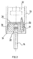
- the punch 14 shown in FIGS. 1 and 2 has been formed by internal high pressure forming pierce manufactured workpiece 16 and is in a feed end position.
- the punch 14 is inserted at one end into a plug hole 17, which in one Bracket block 18 is provided as a through hole.
- the essentially round cylindrical Bracket block with the coaxial plug hole 17 has two between the Plug hole 17 and outer lateral surfaces extending passages 19 and 20, which guides for locking elements 21 and 22 form.
- the one in the guides against one Spring 23 or 24 displaceable locking elements have a tangent to the punch 14 extending cutting edge 25 or 26.
- the locking blades 25 and 26 grip each in a locking recess 27 or 28 in the punch 14.
- the bracket block 18 is provided with an annular shoulder on which an annular sleeve 29 is seated, one Counter stop for the springs 23, 24 forms and bores 35, 36 for the passage of the each end of the locking elements 21, 22 facing away from the plug hole 17.
- the reference numeral 30 designates a pressure plate which has the plug hole 17 one-sided.
- the mounting block 18 and the pressure plate 30 are over four screws 31 connected to a coupling member 32 for coupling to a drive cylinder.
- the mounting block 18, the pressure plate 30 and the coupling member 32 are in a guide sleeve 33 guided, which is inserted into a recess in the workpiece 15 and has an annular step recess 34 at its end facing the tool 15.
- the latching elements 21, 22 are wide Head part with the locking cutting edge 25 or 26 and one surrounded by the coil springs 23, 24 Pen part formed.
- the barb-like, extending tangentially to the punch 14 Latching edges 25, 26 are on both sides above those in the punch 14 provided recesses 27.28.
- the punch 14 has been retracted so far via the coupling member 32 that that its end face is arranged flush with the tool surface and one Forms part of the mold cavity wall.
- the punch 14 is subject to a certain wear, so that it after a certain Operating time must be replaced.
- the punch 14 can now be removed by rotating about its longitudinal axis first the latching with the latching elements 21, 22 is released and the punch 14 is then pulled out of the plug hole 17.
- the latching elements 21, 22 are pressed outwards, the one shown in FIGS. 1 and 2 End of feed position of the punch 14, the ends facing away from the punch the locking elements 21, 22 through the bores 35, 36 into the ring step recess 34 of the guide sleeve 33 can protrude into it.
- a new punch 14 introduced for replacement in the plug hole 17 hits against the inclined sliding surfaces of the locking cutting edges 27, 28 and presses the locking elements 21,22 against the force of the springs 23,29 back until the locking elements 21,22 after further penetration of the punch into the plug hole and possibly after turning the Snap the punch 14 into the notches 27, 28.
- this detent can no longer be solved because the locking elements 21,22 between the punch 14 and the inner wall of the guide sleeve 33 are blocked.
- FIGS. 4 to 6 where the same or equivalent parts with the same, but with the letter a reference number as designated in the previous embodiment.
- FIGS. 4 to 6 differs from the previous embodiment i.a. in that a punch 14a with a deviating from the circular shape Cross section is used.
- a plug hole 17a is provided with a corresponding cross section, so that the punch 14a cannot be rotated in the plug hole 17a.
- the punch 14a has a slide with a head 38 and a bolt 37.
- the Bolt 37 is guided in a longitudinal bore of the punch 14a.
- the one piece with the Bolt 37 connected head 38 of the slide is in a longitudinal recess 39 of the punch 14a is displaceable and has bevels 40, 41 accordingly in the punch 14a provided recesses 27a and 28a.
- a pin 42 engages against the head 38 of the slide on.
- the pin is guided through a bore in a pressure plate 30a and with a head part 43 connected, against which a coil spring 44 rests.
- the headboard 43 and the Coil spring 44 are arranged in a recess 45 in a coupling member 32a.
- the slide is relative to the rest of the pin 37
- Punch punch moved, the locking elements sliding on the bevels 40, 41 21a, 22a are pressed outward and out of rasp engagement with the latching recesses 27a, 28a in punch 14a.
- the punch 14a can then be made the plug hole 17a are pulled out in the feed direction.
- FIGS. 7 and 8 has a punch 14b with a Cross-section, which is circular as in the embodiment of FIGS. 1 to 3.
- Locking elements 21b, 22b are provided with a through recess 48 into which a through a coil spring 49 engages blocking pin 47.
- the blocking pin 47 has an end portion 46 whose diameter is opposite the width of the through recess 48 reduced in the locking elements 21b, 22b and the eccentric to the rest Blocking pin is arranged.
Landscapes
- Engineering & Computer Science (AREA)
- Mechanical Engineering (AREA)
- Punching Or Piercing (AREA)
- Shaping Metal By Deep-Drawing, Or The Like (AREA)
Applications Claiming Priority (2)
| Application Number | Priority Date | Filing Date | Title |
|---|---|---|---|
| DE1999134663 DE19934663A1 (de) | 1999-07-23 | 1999-07-23 | Vorrichtung zum Lochen von Werkstücken beim Innenhochdruckumformen |
| DE19934663 | 1999-07-23 |
Publications (2)
| Publication Number | Publication Date |
|---|---|
| EP1075883A2 true EP1075883A2 (fr) | 2001-02-14 |
| EP1075883A3 EP1075883A3 (fr) | 2003-05-21 |
Family
ID=7915866
Family Applications (1)
| Application Number | Title | Priority Date | Filing Date |
|---|---|---|---|
| EP00114898A Withdrawn EP1075883A3 (fr) | 1999-07-23 | 2000-07-12 | Procédé de poinçonnage de pièces par haute pression interne |
Country Status (2)
| Country | Link |
|---|---|
| EP (1) | EP1075883A3 (fr) |
| DE (1) | DE19934663A1 (fr) |
Families Citing this family (3)
| Publication number | Priority date | Publication date | Assignee | Title |
|---|---|---|---|---|
| DE10358500B4 (de) * | 2003-12-13 | 2007-09-20 | Daimlerchrysler Ag | Lochstempel zum Herstellen von Lochungen in der Wandung von mit Innenhochdruck beaufschlagten hohlen Bauteilen |
| US7159426B1 (en) * | 2005-09-27 | 2007-01-09 | Gm Global Technology Operations, Inc. | Quick change assembly for hydroforming punches |
| CN109047613B (zh) * | 2018-10-16 | 2020-10-30 | 黄杰 | 锻造设备用模具锁位结构 |
Family Cites Families (3)
| Publication number | Priority date | Publication date | Assignee | Title |
|---|---|---|---|---|
| US5398533A (en) * | 1994-05-26 | 1995-03-21 | General Motors Corporation | Apparatus for piercing hydroformed part |
| DE19506067C1 (de) * | 1995-02-22 | 1996-06-20 | Krupp Ag Hoesch Krupp | Verfahren zum Ausschneiden eines Ausschnitts aus der Wandung eines als Hohlkörper ausgebildeten Bauteils und Vorrichtung zur Durchführung des Verfahrens |
| US5666840A (en) * | 1996-06-13 | 1997-09-16 | General Motors Corporation | Method for piercing two aligned holes in a hydroformed tube |
-
1999
- 1999-07-23 DE DE1999134663 patent/DE19934663A1/de not_active Withdrawn
-
2000
- 2000-07-12 EP EP00114898A patent/EP1075883A3/fr not_active Withdrawn
Also Published As
| Publication number | Publication date |
|---|---|
| EP1075883A3 (fr) | 2003-05-21 |
| DE19934663A1 (de) | 2001-01-25 |
Similar Documents
| Publication | Publication Date | Title |
|---|---|---|
| EP1371455B1 (fr) | Dispositif d'accouplement pour verrouiller une connexion à fiches d'un outil | |
| DE2748093C2 (fr) | ||
| DE4235665C2 (de) | Schraubenzieher | |
| DE69522201T2 (de) | Werkzeughalter | |
| DE102011052967B4 (de) | Presszange, Wechselkassette für eine Presszange und Presszangenset | |
| DE4403906A1 (de) | Befestigungsvorrichtung für einen Kronenschneider an einer Welle | |
| DE10261748A1 (de) | Stanzwerkzeug | |
| DE3121286A1 (de) | Backenfutter | |
| CH663920A5 (de) | Schlagbohreinrichtung. | |
| EP1813393B1 (fr) | Outil de scellement | |
| DE3808999A1 (de) | Schluessellose einspannvorrichtung | |
| EP0555633A1 (fr) | Garniture pour poignée de porte | |
| EP1075883A2 (fr) | Procédé de poinçonnage de pièces par haute pression interne | |
| EP0427090A2 (fr) | Support d'outils pour des outils rotatifs, en particulier des lames de scie circulaires, hacheuses etc. | |
| DE2836547C2 (de) | Vorrichtung zum Abziehen von Lagerringen o.dgl. unter Anwendung von Gewindeteilen | |
| DE2647633A1 (de) | Werkzeughalter | |
| DE3219011C2 (fr) | ||
| EP2777848A1 (fr) | Dispositif de serrage ou de préhension | |
| DE29505752U1 (de) | Vorrichtung zum Verbinden von Platten mittels Verschraubung | |
| DE2460433C2 (de) | Auswerfervorrichtung für eine Spritzgieß- oder Druckgießform, mit einem Flachauswerfer | |
| DE10260493A1 (de) | Kraftspannfutter und Ausklinkschlüssel dafür | |
| DE10033207C1 (de) | Einsatzanordnung für ein Formwerkzeug sowie Formwerkzeug mit einer solchen | |
| EP2777850A1 (fr) | Dispositif de serrage ou de préhension | |
| EP2777849A1 (fr) | Dispositif de serrage ou de préhension | |
| EP3106265B1 (fr) | Outil portatif et son procede de fabrication |
Legal Events
| Date | Code | Title | Description |
|---|---|---|---|
| PUAI | Public reference made under article 153(3) epc to a published international application that has entered the european phase |
Free format text: ORIGINAL CODE: 0009012 |
|
| AK | Designated contracting states |
Kind code of ref document: A2 Designated state(s): AT BE CH CY DE DK ES FI FR GB GR IE IT LI LU MC NL PT SE |
|
| AX | Request for extension of the european patent |
Free format text: AL;LT;LV;MK;RO;SI |
|
| PUAL | Search report despatched |
Free format text: ORIGINAL CODE: 0009013 |
|
| AK | Designated contracting states |
Designated state(s): AT BE CH CY DE DK ES FI FR GB GR IE IT LI LU MC NL PT SE |
|
| AX | Request for extension of the european patent |
Extension state: AL LT LV MK RO SI |
|
| AKX | Designation fees paid | ||
| REG | Reference to a national code |
Ref country code: DE Ref legal event code: 8566 |
|
| STAA | Information on the status of an ep patent application or granted ep patent |
Free format text: STATUS: THE APPLICATION IS DEEMED TO BE WITHDRAWN |
|
| 18D | Application deemed to be withdrawn |
Effective date: 20040203 |