EP1075984A2 - Gepolsterter Sitz für Fahrzeuge, insbesondere Kraftfahrzeuge - Google Patents
Gepolsterter Sitz für Fahrzeuge, insbesondere Kraftfahrzeuge Download PDFInfo
- Publication number
- EP1075984A2 EP1075984A2 EP00115015A EP00115015A EP1075984A2 EP 1075984 A2 EP1075984 A2 EP 1075984A2 EP 00115015 A EP00115015 A EP 00115015A EP 00115015 A EP00115015 A EP 00115015A EP 1075984 A2 EP1075984 A2 EP 1075984A2
- Authority
- EP
- European Patent Office
- Prior art keywords
- backrest
- seat according
- air
- cover
- upholstered seat
- Prior art date
- Legal status (The legal status is an assumption and is not a legal conclusion. Google has not performed a legal analysis and makes no representation as to the accuracy of the status listed.)
- Granted
Links
- 238000009423 ventilation Methods 0.000 claims abstract description 26
- 238000001816 cooling Methods 0.000 claims abstract description 18
- 238000004378 air conditioning Methods 0.000 claims abstract description 8
- 239000006260 foam Substances 0.000 claims description 2
- 238000009429 electrical wiring Methods 0.000 claims 1
- 230000008030 elimination Effects 0.000 claims 1
- 238000003379 elimination reaction Methods 0.000 claims 1
- 125000006850 spacer group Chemical group 0.000 claims 1
- 230000007704 transition Effects 0.000 claims 1
- 230000008439 repair process Effects 0.000 description 2
- 239000000243 solution Substances 0.000 description 2
- 238000010276 construction Methods 0.000 description 1
- 238000011161 development Methods 0.000 description 1
- 230000018109 developmental process Effects 0.000 description 1
- 238000011990 functional testing Methods 0.000 description 1
- 239000000463 material Substances 0.000 description 1
- 238000003856 thermoforming Methods 0.000 description 1
Images
Classifications
-
- B—PERFORMING OPERATIONS; TRANSPORTING
- B60—VEHICLES IN GENERAL
- B60N—SEATS SPECIALLY ADAPTED FOR VEHICLES; VEHICLE PASSENGER ACCOMMODATION NOT OTHERWISE PROVIDED FOR
- B60N2/00—Seats specially adapted for vehicles; Arrangement or mounting of seats in vehicles
- B60N2/56—Heating or ventilating devices
- B60N2/5607—Heating or ventilating devices characterised by convection
- B60N2/5621—Heating or ventilating devices characterised by convection by air
- B60N2/5635—Heating or ventilating devices characterised by convection by air coming from the passenger compartment
-
- B—PERFORMING OPERATIONS; TRANSPORTING
- B60—VEHICLES IN GENERAL
- B60N—SEATS SPECIALLY ADAPTED FOR VEHICLES; VEHICLE PASSENGER ACCOMMODATION NOT OTHERWISE PROVIDED FOR
- B60N2/00—Seats specially adapted for vehicles; Arrangement or mounting of seats in vehicles
- B60N2/56—Heating or ventilating devices
- B60N2/5607—Heating or ventilating devices characterised by convection
- B60N2/5621—Heating or ventilating devices characterised by convection by air
- B60N2/5657—Heating or ventilating devices characterised by convection by air blown towards the seat surface
Definitions
- the invention relates to a seat according to the preamble of claim 1.
- the object of the present invention is the ventilation and / or air conditioning of padded To make vehicle seats easier to handle and less expensive.
- the invention provides an (active) modular ventilation and (if necessary) air conditioning unit created for vehicle seats that are characterized by a lightweight, space-saving and inexpensive Characterized construction, is easy to install and remove and therefore simple Functional checks and (possible) repairs made possible.
- Cooling unit 13 For example a Peltier element.
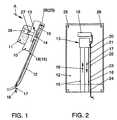
- Cooling unit 13 and fan 14 form a ventilation and air conditioning device for the upholstery 11 of the (partially shown) seat back.
- the fan 14 draws outside air through a supply air duct 15 in the direction of arrow 16 (see in particular FIG. 2).
- heated - exhaust air serves an exhaust air duct 18, which is directly next to the Supply air duct 15 and is arranged parallel to this.
- Supply and exhaust air ducts 15, 18 are like Fig. 1 reveals, on the (facing the back frame 10) inside of the back cover 12 arranged and connected to it, preferably clipped.
- the supply and exhaust air ducts 15, 18 can be customized using the thermoforming process be applied to the backrest trim part (backrest cover 12). That means, that the inlets and outlets (arrows 16, 17) of the supply and exhaust air ducts 15, 18 as required, for example following design and / or comfort conditions.
- the supply and exhaust air ducts 15, 18 are sealed for connection to the fan 14 expediently through seals that allow pressure and tolerance compensation. Foam seals are preferred for this purpose.
- a control unit 19 is used with a electrical cable harness 20 (see in particular Fig. 2).
- the wire harness 20 is - at 21, 22, 23 and 24 - clipped to the backrest cover 12.
- Control unit 19 is also included the backrest cover 12 connected.
- the modular backrest cover 12 / cooling and ventilation device 13 thus also include parts 15, 18, 19 and 20.
- the (detachable) connection of the modular Assembly 12 - 15, 18 - 20 with the backrest frame 10 is done by clipping or screwing. Two attachment points are indicated in the drawing and designated 25, 26.
- the cooling and ventilation device 13, 14 an air-guiding connection piece 27, which is arranged in the padding 11 or this interspersed in a recess 28.
- the connecting piece 27 leads from the fan 14 or from the cooling unit 13 to an air-permeable ventilation layer (not shown) Padding 11, from where the cooling air to an air-permeable (also not shown) Cover of the upholstery 11 arrives.
- the cooling air can flow directly into the backrest cushion 11 can be initiated, which in this case must consist of air-permeable material.
Landscapes
- Engineering & Computer Science (AREA)
- Aviation & Aerospace Engineering (AREA)
- Transportation (AREA)
- Mechanical Engineering (AREA)
- Chair Legs, Seat Parts, And Backrests (AREA)
- Seats For Vehicles (AREA)
Abstract
Description
- Funktionsintegrierte Bauteile
- Kompakte Lösung (wenig Einzelteile)
- Austauschbarkeit
- Einfache Variantensteuerung (Lehnenabdeckung mit oder ohne Belüftungs-Klimatisierungseinheit).
- Fig. 1
- eine Ausführungsform, einer Kraftfahrzeug-Sitzlehne, in Seitenansicht, und
- Fig. 2
- die Sitzlehne nach Fig. 1, in Pfeilrichtung A betrachtet (Lehnenrahmen und Polsterauflage weggelassen).
Claims (17)
- Gepolsterter Sitz für Fahrzeuge, insbesondere Kraftfahrzeuge, mit einer der Polsterung (11) zugeordneten Belüftungseinrichtung (13, 14) auf Basis eines oder mehrerer Ventilatoren (14), wobei Luft angesaugt wird, die - unmittelbar oder mittelbar über eine Kühleinheit (13) - zur Belüftung bzw. Klimatisierung der Polsterung (11) dient, dadurch gekennzeichnet, daß die der Sitzlehne zugeordnete Belüftungseinrichtung (13, 14) zwischen der Lehnenpolsterung (11) und einer rückwärtigen Lehnenabdeckung (12) angeordnet ist und zusammen mit der Lehnenabdeckung (12) eine modulare Baueinheit bildet.
- Gepolsterter Sitz nach Anspruch 1 mit einem die Lehnenpolsterung (11) aufnehmenden Lehnenrahmen (10), dadurch gekennzeichnet, daß die Baueinheit Lehnenabdeckung / Belüftungseinrichtung (12, 13, 14) mit dem Lehnenrahmen (10) lösbar verbunden ist.
- Gepolsterter Sitz nach Anspruch 2, dadurch gekennzeichnet, daß die Baueinheit Lehnenabdeckung / Belüftungseinrichtung (12, 13, 14) mit dem Lehnenrahmen (10) von innen verklipst ist
- Gepolsterter Sitz nach Anspruch 2, dadurch gekennzeichnet, daß die Baueinheit Lehnenabdeckung / Belüftungseinrichtung (12, 13, 14) mit dem Lehnenrahmen (12) von innen verschraubt ist.
- Gepolsterter Sitz nach einem oder mehreren der vorstehenden Ansprüche, dadurch gekennzeichnet, daß in der Lehnenpolsterung (11) ein luftführender Anschlußstutzen (27) angeordnet ist, der vom Luftaustritt des Ventilators (14) bzw. der Kühleinheit (13) zu einer luftdurchflutbaren Ventilationsschicht führt, von wo die Luft zu einem - luftdurchlässig ausgebildeten - Bezug der Lehnenpolsterung (11) gelangen kann.
- Gepolsterter Sitz nach Anspruch 5, dadurch gekennzeichnet, daß als luftdurchflutbare Ventilationsschicht ein Abstandsgewirke dient.
- Gepolsterter Sitz nach einem oder mehreren der Ansprüche 1 - 4 und 6, dadurch gekennzeichnet, daß die vom Ventilator (14) bzw. von der Kühleinheit (13) geförderte Luft unmittelbar in das - zu diesem Zweck insgesamt luftdurchlässig ausgebildete - Lehnenpolster (11) und von dort zum luftdurchlässigen Polsterbezug gelangt.
- Gepolsterter Sitz nach Anspruch 7, dadurch gekennzeichnet, daß die Lehnenabdeckung (12) gegenüber dem Lehnenrahmen (10) abgedichtet ist.
- Gepolsterter Sitz nach einem oder mehreren der vorstehenden Ansprüche, dadurch gekennzeichnet, daß die Baueinheit Lehnenabdeckung / Belüftungseinrichtung (12, 14) einen oder mehrere Ventilator(en) (14) aufweist, die an Zuluftkanäle (15) angeschlossen sind, welche ebenfalls in die Baueinheit Lehnenabdeckung / Belüftungseinrichtung (12, 14) integriert sind.
- Gepolsterter Sitz nach einem oder mehreren der Ansprüche 1 bis 8, dadurch gekennzeichnet, daß die Baueinheit Lehnenabdeckung / Belüftungseinrichtung (12, 13) ein oder mehrere Kühlelement(e) (13) enthält und daß das (die) Kühlelement(e) (13) an Abluftkanäle (18) angeschlossen ist (sind), die ebenfalls in die Baueinheit Lehnenabdeckung / Belüftungseinrichtung (12, 13) integriert sind.
- Gepolsterter Sitz nach Anspruch 9 oder 10, dadurch gekennzeichnet, daß die Zu- und Abluftkanäle (15, 18) parallel zueinander und im wesentlichen auch zu der durch die Sitzlehne (10, 11, 12) gebildeten Ebene und nebeneinander angeordnet sind und daß die Zu- und Abluftkanäle (15, 18) von unten nach oben bzw. von oben nach unten verlaufen, derart, daß - jeweils am unteren Ende der Lehnenabdeckung (12) - die Zuluft in den Zuluftkanal (15) gelangt (Pfeil 16) und die Abluft aus dem Abluftkanal (18) austritt (Pfeil 17).
- Gepolsterter Sitz nach Anspruch 9,10 oder 11 dadurch gekennzeichnet, daß die Zu- und Abluftkanäle (15, 18) auf der Innenseite der Lehnenabdeckung (12) angeordnet und mit dieser verbunden sind.
- Gepolsterter Sitz nach Anspruch 9, dadurch gekennzeichnet, daß die Zuluftkanäle (15) zum jeweiligen Anschluß am Ventilator (14) mittels einen Druck- und Toleranzausgleich ermöglichender Dichtungen, vorzugsweise Schaumdichtungen, abgedichtet sind.
- Gepolsterter Sitz nach einem oder mehreren der vorstehenden Ansprüche, mit einem Steuergerät (19) für das Kühlelement (13) bzw. die Belüftungseinrichtung (13, 14), dadurch gekennzeichnet, daß das Steuergerät (19), inclusive einer hierfür vorgesehenen elektrischen Verkabelung (20), auf der Innenseite der Lehnenabdeckung (12) angeordnet und fixiert ist, derart, daß es einen integrierten Bestandteil der Baueinheit Lehnenabdeckung / Belüftungseinrichtung (12, 13, 14) bildet.
- Gepolsterter Sitz nach einem oder mehreren der vorstehenden Ansprüche, dadurch gekennzeichnet, daß der (die) Ventilator(en) (14) zwecks Geräusch- und Vibrationseliminierung von der Lehnenabdeckung (12) entkoppelt ist (sind).
- Gepolsterter Sitz nach Anspruch 15, dadurch gekennzeichnet, daß eine Eigenentkoppelung des Ventilators (der Ventilatoren) (14) vorgesehen ist.
- Gepolsterter Sitz nach Anspruch 15, dadurch gekennzeichnet, daß der (die) Ventilator(en) (14) mittels Entkoppelungselementen, die am Übergangsbereich zwischen Ventilator(en) (14) und Lehnenabdeckung (12) angeordnet sind, von der Lehnenabdeckung (12) abgekoppelt ist (sind).
Applications Claiming Priority (2)
| Application Number | Priority Date | Filing Date | Title |
|---|---|---|---|
| DE19937464 | 1999-08-07 | ||
| DE19937464A DE19937464A1 (de) | 1999-08-07 | 1999-08-07 | Gepolsterter Sitz für Fahrzeuge, insbesondere Kraftfahrzeuge |
Publications (3)
| Publication Number | Publication Date |
|---|---|
| EP1075984A2 true EP1075984A2 (de) | 2001-02-14 |
| EP1075984A3 EP1075984A3 (de) | 2002-01-16 |
| EP1075984B1 EP1075984B1 (de) | 2003-05-07 |
Family
ID=7917669
Family Applications (1)
| Application Number | Title | Priority Date | Filing Date |
|---|---|---|---|
| EP00115015A Expired - Lifetime EP1075984B1 (de) | 1999-08-07 | 2000-07-24 | Gepolsterter Sitz für Fahrzeuge, insbesondere Kraftfahrzeuge |
Country Status (3)
| Country | Link |
|---|---|
| EP (1) | EP1075984B1 (de) |
| AT (1) | ATE239627T1 (de) |
| DE (2) | DE19937464A1 (de) |
Cited By (7)
| Publication number | Priority date | Publication date | Assignee | Title |
|---|---|---|---|---|
| US6840576B2 (en) | 2001-01-05 | 2005-01-11 | Johnson Controls Technology Company | Ventilated seat |
| US6857697B2 (en) | 2002-08-29 | 2005-02-22 | W.E.T. Automotive Systems Ag | Automotive vehicle seating comfort system |
| US7052091B2 (en) | 2002-07-03 | 2006-05-30 | W.E.T. Automotive Systems Ltd. | Automotive vehicle seat insert |
| US7338117B2 (en) | 2003-09-25 | 2008-03-04 | W.E.T. Automotive System, Ltd. | Ventilated seat |
| US7578552B2 (en) | 2003-10-17 | 2009-08-25 | W.E.T. Automotive Systems Ag | Automotive vehicle seat having a comfort system |
| US7618089B2 (en) | 2005-04-20 | 2009-11-17 | W.E.T. Automotive Systems Ag | Air conditioning system for a seat |
| US9815347B2 (en) | 2009-03-18 | 2017-11-14 | Gentherm Gmbh | Air conditioned object in the interior of a motor vehicle with a switching device |
Families Citing this family (20)
| Publication number | Priority date | Publication date | Assignee | Title |
|---|---|---|---|---|
| US7040710B2 (en) | 2001-01-05 | 2006-05-09 | Johnson Controls Technology Company | Ventilated seat |
| DE20112473U1 (de) | 2001-07-28 | 2002-12-19 | Johnson Controls GmbH, 51399 Burscheid | Klimatisiertes Polsterteil für einen Fahrzeugsitz |
| DE20120516U1 (de) | 2001-12-19 | 2003-04-30 | Johnson Controls GmbH, 51399 Burscheid | Belüftungssystem für ein Polsterteil |
| DE10259621B4 (de) | 2002-12-18 | 2005-12-01 | W.E.T. Automotive Systems Ag | Fahrzeugsitz und zugehörige Klimatisierungseinrichtung |
| DE10259648B4 (de) | 2002-12-18 | 2006-01-26 | W.E.T. Automotive Systems Ag | Klimatisierter Sitz und Klimatisierungseinrichtung für einen ventilierten Sitz |
| DE10316732B4 (de) * | 2003-04-08 | 2013-10-02 | Volkswagen Ag | Verfahren und Vorrichtung zur Regelung von Klima-/Belüftungssitzen in Abhängigkeit der Sitz- und Fahrzeuginnenraumtemperatur |
| DE10316275B4 (de) | 2003-04-08 | 2009-06-18 | Johnson Controls Gmbh | Fahrzeugsitz |
| US7274007B2 (en) | 2003-09-25 | 2007-09-25 | W.E.T. Automotive Systems Ltd. | Control system for operating automotive vehicle components |
| US7370911B2 (en) | 2003-10-17 | 2008-05-13 | W.E.T. Automotive Systems, Ag | Automotive vehicle seat insert |
| US7461892B2 (en) | 2003-12-01 | 2008-12-09 | W.E.T. Automotive Systems, A.C. | Valve layer for a seat |
| DE102004057640B4 (de) * | 2004-11-30 | 2011-05-26 | Daimler Ag | Luftversorgungseinrichtung für einen Fahrzeugsitz eines Kraftwagens |
| US7478869B2 (en) | 2005-08-19 | 2009-01-20 | W.E.T. Automotive Systems, Ag | Automotive vehicle seat insert |
| DE102009058996B4 (de) | 2008-12-21 | 2012-12-06 | W.E.T. Automotive Systems Ag | Belüftungseinrichtung |
| DE202010002050U1 (de) | 2009-02-18 | 2010-07-15 | W.E.T. Automotive Systems Ag | Klimatisierungseinrichtung für Fahrzeugsitze |
| DE102012023909B4 (de) | 2012-07-25 | 2021-08-19 | Gentherm Gmbh | Nackenwärmer |
| CN104742772B (zh) * | 2013-12-26 | 2017-10-20 | 捷温汽车系统(中国)有限公司 | 尤其用于交通运输工具座椅中的颈部加热装置的热风机 |
| DE112016003936B4 (de) | 2015-08-28 | 2025-01-30 | Gentherm Inc. | Einen Sitz sowie eine Kopfstütze umfassende Baugruppe und Luft-Temperierungssystem eines Sitzes |
| DE102016009884A1 (de) | 2015-12-14 | 2017-06-14 | Gentherm Gmbh | Nackengebläse für einen Fahrzeugsitz und Regel-Verfahren dafür |
| KR102140506B1 (ko) | 2016-02-10 | 2020-08-04 | 젠썸 게엠베하 | 차량 시트의 사용자 경부 부위의 온도 조절 장치 |
| US10625643B2 (en) | 2017-06-14 | 2020-04-21 | Gentherm Gmbh | Conditioning system with blower attachment system and method of attachment |
Citations (3)
| Publication number | Priority date | Publication date | Assignee | Title |
|---|---|---|---|---|
| DE19604477A1 (de) | 1996-02-08 | 1997-08-14 | Teves Gmbh Alfred | Kühleinrichtung für Kraftfahrzeugsitze |
| DE19634370A1 (de) | 1996-08-26 | 1998-03-05 | Daimler Benz Ag | Fahrzeugsitz |
| DE19703516C1 (de) | 1997-01-31 | 1998-05-07 | Daimler Benz Ag | Fahrzeugsitz |
Family Cites Families (8)
| Publication number | Priority date | Publication date | Assignee | Title |
|---|---|---|---|---|
| DE4112631C1 (en) * | 1991-04-18 | 1992-04-30 | Keiper Recaro Gmbh & Co, 5630 Remscheid, De | Motor vehicle seat with moisture removal inset - incorporating air channel at rear of backrest with air dryer |
| DE19628698C1 (de) * | 1996-07-17 | 1997-10-09 | Daimler Benz Ag | Fahrzeugsitz |
| DE19830797B4 (de) * | 1997-07-14 | 2007-10-04 | Denso Corp., Kariya | Fahrzeugsitz-Klimaanlage |
| DE19737636A1 (de) * | 1997-08-28 | 1999-03-11 | Aisin Seiki | Körperstützvorrichtung und Verfahren zu ihrer Klimatisierung |
| DE19805173C1 (de) * | 1998-02-10 | 1999-06-02 | Daimler Chrysler Ag | Fahrzeugsitz |
| DE19805174C1 (de) * | 1998-02-10 | 1999-06-02 | Daimler Chrysler Ag | Fahrzeugsitz |
| DE19851979C2 (de) * | 1998-11-11 | 2000-08-31 | Daimler Chrysler Ag | Temperaturfühler für einen klimatisierten Fahrzeugsitz |
| DE19920062C2 (de) * | 1999-05-03 | 2003-11-06 | Daimler Chrysler Ag | Fahrzeugsitz |
-
1999
- 1999-08-07 DE DE19937464A patent/DE19937464A1/de not_active Withdrawn
-
2000
- 2000-07-24 DE DE50002048T patent/DE50002048D1/de not_active Expired - Lifetime
- 2000-07-24 EP EP00115015A patent/EP1075984B1/de not_active Expired - Lifetime
- 2000-07-24 AT AT00115015T patent/ATE239627T1/de not_active IP Right Cessation
Patent Citations (3)
| Publication number | Priority date | Publication date | Assignee | Title |
|---|---|---|---|---|
| DE19604477A1 (de) | 1996-02-08 | 1997-08-14 | Teves Gmbh Alfred | Kühleinrichtung für Kraftfahrzeugsitze |
| DE19634370A1 (de) | 1996-08-26 | 1998-03-05 | Daimler Benz Ag | Fahrzeugsitz |
| DE19703516C1 (de) | 1997-01-31 | 1998-05-07 | Daimler Benz Ag | Fahrzeugsitz |
Cited By (11)
| Publication number | Priority date | Publication date | Assignee | Title |
|---|---|---|---|---|
| US6840576B2 (en) | 2001-01-05 | 2005-01-11 | Johnson Controls Technology Company | Ventilated seat |
| US7052091B2 (en) | 2002-07-03 | 2006-05-30 | W.E.T. Automotive Systems Ltd. | Automotive vehicle seat insert |
| US7197801B2 (en) | 2002-07-03 | 2007-04-03 | W.E.T. Automotive Systems Ltd. | Automotive vehicle seat insert |
| US7637573B2 (en) | 2002-07-03 | 2009-12-29 | W.E.T. Automotive Systems Ag | Automotive vehicle seating insert |
| US6857697B2 (en) | 2002-08-29 | 2005-02-22 | W.E.T. Automotive Systems Ag | Automotive vehicle seating comfort system |
| US7083227B2 (en) | 2002-08-29 | 2006-08-01 | W.E.T. Automotive Systems, Ag | Automotive vehicle seating comfort system |
| US7338117B2 (en) | 2003-09-25 | 2008-03-04 | W.E.T. Automotive System, Ltd. | Ventilated seat |
| US7356912B2 (en) | 2003-09-25 | 2008-04-15 | W.E.T. Automotive Systems, Ltd. | Method for ventilating a seat |
| US7578552B2 (en) | 2003-10-17 | 2009-08-25 | W.E.T. Automotive Systems Ag | Automotive vehicle seat having a comfort system |
| US7618089B2 (en) | 2005-04-20 | 2009-11-17 | W.E.T. Automotive Systems Ag | Air conditioning system for a seat |
| US9815347B2 (en) | 2009-03-18 | 2017-11-14 | Gentherm Gmbh | Air conditioned object in the interior of a motor vehicle with a switching device |
Also Published As
| Publication number | Publication date |
|---|---|
| EP1075984A3 (de) | 2002-01-16 |
| DE50002048D1 (de) | 2003-06-12 |
| EP1075984B1 (de) | 2003-05-07 |
| ATE239627T1 (de) | 2003-05-15 |
| DE19937464A1 (de) | 2001-02-08 |
Similar Documents
| Publication | Publication Date | Title |
|---|---|---|
| EP1075984B1 (de) | Gepolsterter Sitz für Fahrzeuge, insbesondere Kraftfahrzeuge | |
| DE102004005573B4 (de) | Fahrzeugsitz | |
| EP1600375B1 (de) | Sitz, insbesondere Fluggastsitz | |
| DE19805173C1 (de) | Fahrzeugsitz | |
| DE60112473T2 (de) | Belüfteter fahrzeugsitz | |
| DE19804100C1 (de) | Fahrzeugsitz | |
| DE10207489B4 (de) | Kraftfahrzeugsitz | |
| EP1266794A2 (de) | Fahrzeugsitz mit Sitzbelüftung | |
| DE102012006074A1 (de) | Kraftfahrzeugsitz | |
| EP1193095A3 (de) | Windschutzeinrichtung für einen offenen Kraftwagen | |
| DE102017003550A1 (de) | Verfahren zum Betrieb eines Heizungs-, Lüftungs- und/oder Klimatisierungssystems und Heizungs-, Lüftungs- und/oder Klimatisierungssystem | |
| DE102007031323B4 (de) | Sitzbelüftungseinrichtung für ein Polster eines Fahrzeugsitzes | |
| EP1250245B1 (de) | Sitz mit einer klimatisierbaren Polsteranordnung, insbesondere Kraftfahrzeugsitz | |
| DE102018125733B4 (de) | Sitzbaugruppe einschliesslich einer modularen Schaumstoffanordnung mit einem modularen Entlüftungsabschnitt und Verfahren zum Herstellen derselben | |
| DE102009047959B4 (de) | Heizungs-, Lüftungs- und Klimatisierungssystem für ein Fahrzeug | |
| DE102007031322B3 (de) | Sitzbelüftungseinrichtung für einen Fahrzeugsitz | |
| DE102010010476A1 (de) | Sitzklimatisierungsanlage für einen Fahrzeugsitz | |
| DE102012011398A1 (de) | Sitzanlage, insbesondere Fahrzeugsitz, für einen Kraftwagen | |
| DE10059358A1 (de) | Fahrzeugsitz mit Lüftung | |
| DE19948735B4 (de) | Verfahren und Einrichtung zur Klimatisierung von Fahrzeugsitzen | |
| DE10056414B4 (de) | Belüftete Fußstütze für ein Kraftfahrzeug | |
| DE102005003849B3 (de) | Fahrzeugsitz mit Belüftungsvorrichtung | |
| DE19540020A1 (de) | Baueinheit für ein Kraftfahrzeug | |
| DE102015213299A1 (de) | Personenkraftwagen mit belüftetem Fondfußraum | |
| DE602004005988T2 (de) | Trägerstruktur für das Armaturenbrett eines Kraftfahrzeugs |
Legal Events
| Date | Code | Title | Description |
|---|---|---|---|
| PUAI | Public reference made under article 153(3) epc to a published international application that has entered the european phase |
Free format text: ORIGINAL CODE: 0009012 |
|
| AK | Designated contracting states |
Kind code of ref document: A2 Designated state(s): AT BE CH CY DE DK ES FI FR GB GR IE IT LI LU MC NL PT SE |
|
| AX | Request for extension of the european patent |
Free format text: AL;LT;LV;MK;RO;SI |
|
| PUAL | Search report despatched |
Free format text: ORIGINAL CODE: 0009013 |
|
| AK | Designated contracting states |
Kind code of ref document: A3 Designated state(s): AT BE CH CY DE DK ES FI FR GB GR IE IT LI LU MC NL PT SE |
|
| AX | Request for extension of the european patent |
Free format text: AL;LT;LV;MK;RO;SI |
|
| 17P | Request for examination filed |
Effective date: 20020716 |
|
| AKX | Designation fees paid |
Free format text: AT BE CH CY DE DK ES FI FR GB GR IE IT LI LU MC NL PT SE |
|
| GRAH | Despatch of communication of intention to grant a patent |
Free format text: ORIGINAL CODE: EPIDOS IGRA |
|
| GRAH | Despatch of communication of intention to grant a patent |
Free format text: ORIGINAL CODE: EPIDOS IGRA |
|
| GRAA | (expected) grant |
Free format text: ORIGINAL CODE: 0009210 |
|
| AK | Designated contracting states |
Designated state(s): AT BE CH CY DE DK ES FI FR GB GR IE IT LI LU MC NL PT SE |
|
| PG25 | Lapsed in a contracting state [announced via postgrant information from national office to epo] |
Ref country code: IT Free format text: LAPSE BECAUSE OF FAILURE TO SUBMIT A TRANSLATION OF THE DESCRIPTION OR TO PAY THE FEE WITHIN THE PRESCRIBED TIME-LIMIT;WARNING: LAPSES OF ITALIAN PATENTS WITH EFFECTIVE DATE BEFORE 2007 MAY HAVE OCCURRED AT ANY TIME BEFORE 2007. THE CORRECT EFFECTIVE DATE MAY BE DIFFERENT FROM THE ONE RECORDED. Effective date: 20030507 Ref country code: GB Free format text: LAPSE BECAUSE OF FAILURE TO SUBMIT A TRANSLATION OF THE DESCRIPTION OR TO PAY THE FEE WITHIN THE PRESCRIBED TIME-LIMIT Effective date: 20030507 Ref country code: IE Free format text: LAPSE BECAUSE OF NON-PAYMENT OF DUE FEES Effective date: 20030507 Ref country code: NL Free format text: LAPSE BECAUSE OF FAILURE TO SUBMIT A TRANSLATION OF THE DESCRIPTION OR TO PAY THE FEE WITHIN THE PRESCRIBED TIME-LIMIT Effective date: 20030507 Ref country code: FI Free format text: LAPSE BECAUSE OF FAILURE TO SUBMIT A TRANSLATION OF THE DESCRIPTION OR TO PAY THE FEE WITHIN THE PRESCRIBED TIME-LIMIT Effective date: 20030507 |
|
| REG | Reference to a national code |
Ref country code: GB Ref legal event code: FG4D Free format text: NOT ENGLISH |
|
| REG | Reference to a national code |
Ref country code: CH Ref legal event code: EP |
|
| REG | Reference to a national code |
Ref country code: IE Ref legal event code: FG4D Free format text: GERMAN |
|
| REF | Corresponds to: |
Ref document number: 50002048 Country of ref document: DE Date of ref document: 20030612 Kind code of ref document: P |
|
| PG25 | Lapsed in a contracting state [announced via postgrant information from national office to epo] |
Ref country code: CY Free format text: LAPSE BECAUSE OF FAILURE TO SUBMIT A TRANSLATION OF THE DESCRIPTION OR TO PAY THE FEE WITHIN THE PRESCRIBED TIME-LIMIT Effective date: 20030724 Ref country code: LU Free format text: LAPSE BECAUSE OF NON-PAYMENT OF DUE FEES Effective date: 20030724 Ref country code: AT Free format text: LAPSE BECAUSE OF NON-PAYMENT OF DUE FEES Effective date: 20030724 |
|
| PG25 | Lapsed in a contracting state [announced via postgrant information from national office to epo] |
Ref country code: BE Free format text: LAPSE BECAUSE OF NON-PAYMENT OF DUE FEES Effective date: 20030731 Ref country code: MC Free format text: LAPSE BECAUSE OF NON-PAYMENT OF DUE FEES Effective date: 20030731 |
|
| PG25 | Lapsed in a contracting state [announced via postgrant information from national office to epo] |
Ref country code: SE Free format text: LAPSE BECAUSE OF FAILURE TO SUBMIT A TRANSLATION OF THE DESCRIPTION OR TO PAY THE FEE WITHIN THE PRESCRIBED TIME-LIMIT Effective date: 20030807 Ref country code: GR Free format text: LAPSE BECAUSE OF FAILURE TO SUBMIT A TRANSLATION OF THE DESCRIPTION OR TO PAY THE FEE WITHIN THE PRESCRIBED TIME-LIMIT Effective date: 20030807 Ref country code: PT Free format text: LAPSE BECAUSE OF FAILURE TO SUBMIT A TRANSLATION OF THE DESCRIPTION OR TO PAY THE FEE WITHIN THE PRESCRIBED TIME-LIMIT Effective date: 20030807 Ref country code: DK Free format text: LAPSE BECAUSE OF FAILURE TO SUBMIT A TRANSLATION OF THE DESCRIPTION OR TO PAY THE FEE WITHIN THE PRESCRIBED TIME-LIMIT Effective date: 20030807 |
|
| PG25 | Lapsed in a contracting state [announced via postgrant information from national office to epo] |
Ref country code: ES Free format text: LAPSE BECAUSE OF FAILURE TO SUBMIT A TRANSLATION OF THE DESCRIPTION OR TO PAY THE FEE WITHIN THE PRESCRIBED TIME-LIMIT Effective date: 20030818 |
|
| NLV1 | Nl: lapsed or annulled due to failure to fulfill the requirements of art. 29p and 29m of the patents act | ||
| GBV | Gb: ep patent (uk) treated as always having been void in accordance with gb section 77(7)/1977 [no translation filed] |
Effective date: 20030507 |
|
| ET | Fr: translation filed | ||
| REG | Reference to a national code |
Ref country code: IE Ref legal event code: FD4D Ref document number: 1075984E Country of ref document: IE |
|
| BERE | Be: lapsed |
Owner name: *VOLKSWAGEN A.G. Effective date: 20030731 |
|
| PLBE | No opposition filed within time limit |
Free format text: ORIGINAL CODE: 0009261 |
|
| STAA | Information on the status of an ep patent application or granted ep patent |
Free format text: STATUS: NO OPPOSITION FILED WITHIN TIME LIMIT |
|
| 26N | No opposition filed |
Effective date: 20040210 |
|
| PG25 | Lapsed in a contracting state [announced via postgrant information from national office to epo] |
Ref country code: LI Free format text: LAPSE BECAUSE OF NON-PAYMENT OF DUE FEES Effective date: 20040731 Ref country code: CH Free format text: LAPSE BECAUSE OF NON-PAYMENT OF DUE FEES Effective date: 20040731 |
|
| REG | Reference to a national code |
Ref country code: CH Ref legal event code: PL |
|
| REG | Reference to a national code |
Ref country code: FR Ref legal event code: PLFP Year of fee payment: 16 |
|
| REG | Reference to a national code |
Ref country code: FR Ref legal event code: PLFP Year of fee payment: 17 |
|
| PGFP | Annual fee paid to national office [announced via postgrant information from national office to epo] |
Ref country code: DE Payment date: 20160731 Year of fee payment: 17 |
|
| PGFP | Annual fee paid to national office [announced via postgrant information from national office to epo] |
Ref country code: FR Payment date: 20160728 Year of fee payment: 17 |
|
| REG | Reference to a national code |
Ref country code: DE Ref legal event code: R079 Ref document number: 50002048 Country of ref document: DE Free format text: PREVIOUS MAIN CLASS: B60N0002440000 Ipc: B60N0002900000 |
|
| REG | Reference to a national code |
Ref country code: DE Ref legal event code: R119 Ref document number: 50002048 Country of ref document: DE |
|
| REG | Reference to a national code |
Ref country code: FR Ref legal event code: ST Effective date: 20180330 |
|
| PG25 | Lapsed in a contracting state [announced via postgrant information from national office to epo] |
Ref country code: DE Free format text: LAPSE BECAUSE OF NON-PAYMENT OF DUE FEES Effective date: 20180201 |
|
| PG25 | Lapsed in a contracting state [announced via postgrant information from national office to epo] |
Ref country code: FR Free format text: LAPSE BECAUSE OF NON-PAYMENT OF DUE FEES Effective date: 20170731 |