EP1076029B1 - Méthode de gestion de la source d'énergie d'un véhicule autonome dans un système de transport - Google Patents
Méthode de gestion de la source d'énergie d'un véhicule autonome dans un système de transport Download PDFInfo
- Publication number
- EP1076029B1 EP1076029B1 EP00115387A EP00115387A EP1076029B1 EP 1076029 B1 EP1076029 B1 EP 1076029B1 EP 00115387 A EP00115387 A EP 00115387A EP 00115387 A EP00115387 A EP 00115387A EP 1076029 B1 EP1076029 B1 EP 1076029B1
- Authority
- EP
- European Patent Office
- Prior art keywords
- energy
- vehicle
- travel
- energy resource
- managing
- Prior art date
- Legal status (The legal status is an assumption and is not a legal conclusion. Google has not performed a legal analysis and makes no representation as to the accuracy of the status listed.)
- Expired - Lifetime
Links
- 238000000034 method Methods 0.000 title claims description 14
- 230000000750 progressive effect Effects 0.000 claims 1
- 238000004146 energy storage Methods 0.000 description 6
- 230000008569 process Effects 0.000 description 6
- 230000008878 coupling Effects 0.000 description 4
- 238000010168 coupling process Methods 0.000 description 4
- 238000005859 coupling reaction Methods 0.000 description 4
- 238000005259 measurement Methods 0.000 description 4
- 230000006870 function Effects 0.000 description 3
- 238000012544 monitoring process Methods 0.000 description 3
- 239000002253 acid Substances 0.000 description 2
- 239000003990 capacitor Substances 0.000 description 2
- 238000006073 displacement reaction Methods 0.000 description 2
- 230000000694 effects Effects 0.000 description 2
- 238000005457 optimization Methods 0.000 description 2
- 238000012360 testing method Methods 0.000 description 2
- 230000001960 triggered effect Effects 0.000 description 2
- 238000013459 approach Methods 0.000 description 1
- 230000005540 biological transmission Effects 0.000 description 1
- 238000002485 combustion reaction Methods 0.000 description 1
- 239000000446 fuel Substances 0.000 description 1
- 238000007726 management method Methods 0.000 description 1
- 238000012545 processing Methods 0.000 description 1
- 230000001502 supplementing effect Effects 0.000 description 1
Images

Classifications
-
- B—PERFORMING OPERATIONS; TRANSPORTING
- B66—HOISTING; LIFTING; HAULING
- B66B—ELEVATORS; ESCALATORS OR MOVING WALKWAYS
- B66B1/00—Control systems of elevators in general
- B66B1/24—Control systems with regulation, i.e. with retroactive action, for influencing travelling speed, acceleration, or deceleration
- B66B1/28—Control systems with regulation, i.e. with retroactive action, for influencing travelling speed, acceleration, or deceleration electrical
- B66B1/30—Control systems with regulation, i.e. with retroactive action, for influencing travelling speed, acceleration, or deceleration electrical effective on driving gear, e.g. acting on power electronics, on inverter or rectifier controlled motor
-
- B—PERFORMING OPERATIONS; TRANSPORTING
- B60—VEHICLES IN GENERAL
- B60L—PROPULSION OF ELECTRICALLY-PROPELLED VEHICLES; SUPPLYING ELECTRIC POWER FOR AUXILIARY EQUIPMENT OF ELECTRICALLY-PROPELLED VEHICLES; ELECTRODYNAMIC BRAKE SYSTEMS FOR VEHICLES IN GENERAL; MAGNETIC SUSPENSION OR LEVITATION FOR VEHICLES; MONITORING OPERATING VARIABLES OF ELECTRICALLY-PROPELLED VEHICLES; ELECTRIC SAFETY DEVICES FOR ELECTRICALLY-PROPELLED VEHICLES
- B60L15/00—Methods, circuits, or devices for controlling the traction-motor speed of electrically-propelled vehicles
- B60L15/20—Methods, circuits, or devices for controlling the traction-motor speed of electrically-propelled vehicles for control of the vehicle or its driving motor to achieve a desired performance, e.g. speed, torque, programmed variation of speed
- B60L15/2009—Methods, circuits, or devices for controlling the traction-motor speed of electrically-propelled vehicles for control of the vehicle or its driving motor to achieve a desired performance, e.g. speed, torque, programmed variation of speed for braking
-
- B—PERFORMING OPERATIONS; TRANSPORTING
- B60—VEHICLES IN GENERAL
- B60L—PROPULSION OF ELECTRICALLY-PROPELLED VEHICLES; SUPPLYING ELECTRIC POWER FOR AUXILIARY EQUIPMENT OF ELECTRICALLY-PROPELLED VEHICLES; ELECTRODYNAMIC BRAKE SYSTEMS FOR VEHICLES IN GENERAL; MAGNETIC SUSPENSION OR LEVITATION FOR VEHICLES; MONITORING OPERATING VARIABLES OF ELECTRICALLY-PROPELLED VEHICLES; ELECTRIC SAFETY DEVICES FOR ELECTRICALLY-PROPELLED VEHICLES
- B60L2260/00—Operating Modes
- B60L2260/20—Drive modes; Transition between modes
- B60L2260/32—Auto pilot mode
-
- Y—GENERAL TAGGING OF NEW TECHNOLOGICAL DEVELOPMENTS; GENERAL TAGGING OF CROSS-SECTIONAL TECHNOLOGIES SPANNING OVER SEVERAL SECTIONS OF THE IPC; TECHNICAL SUBJECTS COVERED BY FORMER USPC CROSS-REFERENCE ART COLLECTIONS [XRACs] AND DIGESTS
- Y02—TECHNOLOGIES OR APPLICATIONS FOR MITIGATION OR ADAPTATION AGAINST CLIMATE CHANGE
- Y02T—CLIMATE CHANGE MITIGATION TECHNOLOGIES RELATED TO TRANSPORTATION
- Y02T10/00—Road transport of goods or passengers
- Y02T10/60—Other road transportation technologies with climate change mitigation effect
- Y02T10/64—Electric machine technologies in electromobility
-
- Y—GENERAL TAGGING OF NEW TECHNOLOGICAL DEVELOPMENTS; GENERAL TAGGING OF CROSS-SECTIONAL TECHNOLOGIES SPANNING OVER SEVERAL SECTIONS OF THE IPC; TECHNICAL SUBJECTS COVERED BY FORMER USPC CROSS-REFERENCE ART COLLECTIONS [XRACs] AND DIGESTS
- Y02—TECHNOLOGIES OR APPLICATIONS FOR MITIGATION OR ADAPTATION AGAINST CLIMATE CHANGE
- Y02T—CLIMATE CHANGE MITIGATION TECHNOLOGIES RELATED TO TRANSPORTATION
- Y02T10/00—Road transport of goods or passengers
- Y02T10/60—Other road transportation technologies with climate change mitigation effect
- Y02T10/72—Electric energy management in electromobility
Definitions
- the invention relates to a method for managing the energy resource of an autonomous vehicle of at least one vehicle having transport system, wherein the vehicle is provided for the transport of people and / or goods in the vertical and / or horizontal direction and for the movement of the vehicle by means of the energy resource powered drive is provided, wherein the energy source is supplied to at least one charging station with energy.
- a disadvantage of the known device is that the elevator car is not ready for use in any case, because the charging of the battery always takes place only when the elevator car is on the top floor. In particular, in successive trips that do not lead to the top floor, the battery may be discharged prematurely.
- the invention aims to remedy this situation.
- the invention as characterized in claim 1 solves the problem of avoiding the disadvantages of the known device and to manage the energy resource of an autonomous vehicle of a transport system.
- the advantages achieved by the invention are essentially to be seen in the fact that with the management of the energy resource, the vehicle can be used continuously and without a load-related interruption, which significantly improves the performance of the entire transport system. It is also advantageous that the vehicle can independently start a charging station. The vehicle is thus more independent and has a greater freedom of movement.
- the load can be included in the distance specified by driving orders.
- the present invention relates to the energy supply of an autonomous vehicle of a transport system, which may be, for example, an elevator system with at least one elevator shaft, in which at least one vehicle or at least one elevator car in terms of control and drive high autonomy reversed, wherein the direction of travel can be vertical and / or horizontal.
- the vehicle is moved by means of the drive.
- the drive is supplied with electrical energy by means of an energy source in the form of an energy store, for example a battery.
- a supply unit is provided at at least one stop, by means of which electrical energy is transmitted from a stationary energy supply, for example from the public network or from a solar generator to the energy storage device.
- a coupling establishes the connection between the stationary power supply and the vehicle.
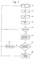
- Fig. 1 shows a flowchart for managing and recharging the energy resource of an autonomous vehicle.
- a first step S1 the energy Es still present in the storage medium is determined.
- the energy Es In the case of a storage medium consisting of capacitors, it is sufficient to measure the voltage, because the charge and thus the energy can be determined from the product of capacitance and voltage.
- the stored energy In the case of a battery as a storage medium, for example, the stored energy can be determined by means of continuous measurement of the voltage and of the current during load / charge.
- the energy Ep (t) necessary for the upcoming driving jobs is determined as a function of time t, whereby the vehicle's own weight, driving distance, driving direction, driving profile, load, etc.
- the energy for a particular driving job is determined when determining the energy Ep (t ).
- the energy for a particular driving job can also be determined in advance by means of a learning run and stored and used in determining the total energy Ep (t) for the driving jobs.
- the energy supply Ef (t) of all planned stops of a certain period of time Charge of the energy storage of the vehicle determined.
- Fig. 3 shows by way of example the course of Es, Ep (t), Ef (t) and dE (t).
- step S5 it is checked whether the energy balance dE (t) is greater than zero. If the energy storage device of the vehicle already has sufficient energy reserves and / or sufficient energy can be supplied during the execution of the planned activities, step S5 is left with a result symbolized with J and the process is started again with step S1. If the test carried out in step 55 ends with a negative result symbolized as N, the process is continued with step S6, in which the charging stations are determined, for example, based on a plan of the charging stations, which ensure a positive energy balance.
- step S7 If several possible charging stations are available, the choice can be based on an optimization criterion, for example based on the time required for the charge. If, as shown in step S7, at least one charging station is available, the process in step S8 is continued, in which the approach of the charging station and the charge of the energy storage is included in the timetable. Thereafter, the process is started again with step S1. If no charging station is available, then the journey is interrupted and triggered a relaxation in step S9. After relaxation, the process continues with step S1.
- the determination of the currently available amount of energy takes place. This can be done by a direct measurement or by a continuous tracking of the energy balance.
- a direct measurement is possible for example in capacitors by measuring the charging voltage, or in internal combustion engines by weight or volume measurement of the fuel stock or thermal energy storage by measuring the temperature or lead acid batteries by measuring the acid density.
- the tracking of the energy balance is based on the continuous recording of the energy flow (power) flowing to and from the storage tank and the summation thereof. In the case of certain events, e.g. Full fueling, a calibration of the balance be carried out.
- the vehicle has a timetable which ensures the processing of the upcoming transport orders.
- the timetable shows the (expected) position of the vehicle as a function of time and can be generated by various methods.
- the vehicle ascertains the energy requirement Ep (t) necessary for the execution of the timetable, taking into account the persons and / or goods to be transported. This can be done, for example, by supplementing the timetable with topological information and thereby determining the physical work required for transport in the gravitational field, which is then determined by the expected losses is supplemented.
- Another method is to consult a table that shows the energy demand as a function of the transported goods for all possible routes. The table can be updated during operation.
- the time profile of the energy supply Ef (t) is determined. For this purpose, for example, in the timetable an award of those stops take place at which an energy supply is planned.
- the amount of energy supplied at this station is determined, for example, on the basis of a corresponding entry in the timetable and arranged in chronological order. As energy supply also a possible recuperation is to be counted.
- the energy reserve dE (t) available at each future time t is calculated.
- the equation dE (t) Es - Ep (t) + Ef (t) can be used, which represents the energy balance of the energy source.
- dE (t) is always positive, or greater than a well-defined minimum reserve, until the end of all travel orders, then no new refueling stops are necessary and the monitoring process can be continued with step S1, if necessary while maintaining a certain waiting time.
- the energy reserve available at the time of termination of all travel orders may be subject to an additional restriction, for example depending on the final position or the expected further driving orders.
- At least one refueling stop is determined so that the criterion in S5 turns out to be positive, meaning that no further refueling stops are necessary.
- the criterion in S5 turns out to be positive, meaning that no further refueling stops are necessary.
- those are determined which have a consistently positive energy balance according to S5 result. This can be done by provisionally scheduling each possible charging station and carrying out the calculations according to S3, S4 and S5. If the test in S5 is positive, the corresponding station will be added to the list of possible candidates. Combinations of several charging stations are also possible.
- a single one is selected from this and scheduled in the timetable.
- the selection can be made on the basis of a specific optimization criterion, for example the time required for refueling.
- the further monitoring process is continued, if necessary, while maintaining a certain waiting time, with the step S1.
- the necessary to relax the vehicle actions are triggered. This may include, for example, the request of a relaxation vehicle 1, which brings about a suitable coupling device refueling of the memory, so that subsequently again an autonomous activity is possible. Likewise, a mechanical shift can take place up to the next refueling point. If the vehicle is in a state in which it has sufficient energy reserves for further execution, the monitoring process is continued with step S1.
- Fig. 2 shows a variant with mechanical coupling
- each vehicle of the transport system has at least one buffer 4, which allows a mutual displacement of the vehicles 1,2. This is installed so that a force from the driving to the driven vehicle is possible.
- the concatenation of 3 safety-relevant signals from safety circuits 7 of the two vehicles 1, 2 can be achieved via a positively driven electrical contact 5.
- the coordination of the processes can take place via corresponding signal lines 6 and transmission protocols.
Landscapes
- Engineering & Computer Science (AREA)
- Automation & Control Theory (AREA)
- Power Engineering (AREA)
- Transportation (AREA)
- Mechanical Engineering (AREA)
- Electric Propulsion And Braking For Vehicles (AREA)
Claims (4)
- Méthode de gestion de la source d'énergie d'un véhicule autonome d'un système de transport comprenant au moins un véhicule, étant précisé que le véhicule est destiné à transporter des personnes et/ou des produits dans le sens vertical et/ou horizontal, qu'il est prévu pour déplacer ledit véhicule un entraînement alimenté grâce à la source d'énergie, et que la source d'énergie est alimentée en énergie au niveau d'au moins une station de charge,
caractérisée en ce qu'un bilan énergétique est défini en fonction de paramètres de véhicule et de circulation, et en ce que la station de charge destinée à alimenter en énergie la source d'énergie est définie en fonction du bilan énergétique. - Méthode de gestion de la source d'énergie d'un véhicule autonome selon la revendication 1, caractérisée en ce que le bilan énergétique est calculé suivant la formule

Es désignant l'énergie encore présente dans la source d'énergie,
Ep(t) l'énergie nécessaire pour les ordres de trajet en attente, en fonction du temps t, étant précisé que des paramètres de véhicule et de circulation comme par exemple le poids propre du véhicule, la distance à parcourir, le sens et le profil du trajet, la charge, etc. de chaque ordre de trajet sont pris en compte, et
Ef(t) l'apport en énergie pour alimenter en énergie la source d'énergie. - Méthode de gestion de la source d'énergie d'un véhicule autonome selon la revendication 1 ou 2, caractérisée en ce que l'arrêt et l'alimentation de la source d'énergie sont intégrés dans le plan de circulation du véhicule.
- Méthode de gestion de la source d'énergie d'un véhicule autonome selon l'une des revendications précédentes, caractérisée en ce qu'un dépannage a lieu au cas où aucune station de charge n'est accessible, un véhicule de dépannage (1) du système de transport alimentant en énergie le véhicule à dépanner (2) ou s'accouplant mécaniquement avec lui et l'amenant à une station de charge.
Priority Applications (1)
| Application Number | Priority Date | Filing Date | Title |
|---|---|---|---|
| EP00115387A EP1076029B1 (fr) | 1999-07-22 | 2000-07-17 | Méthode de gestion de la source d'énergie d'un véhicule autonome dans un système de transport |
Applications Claiming Priority (3)
| Application Number | Priority Date | Filing Date | Title |
|---|---|---|---|
| EP99810659 | 1999-07-22 | ||
| EP99810659 | 1999-07-22 | ||
| EP00115387A EP1076029B1 (fr) | 1999-07-22 | 2000-07-17 | Méthode de gestion de la source d'énergie d'un véhicule autonome dans un système de transport |
Publications (2)
| Publication Number | Publication Date |
|---|---|
| EP1076029A1 EP1076029A1 (fr) | 2001-02-14 |
| EP1076029B1 true EP1076029B1 (fr) | 2008-03-05 |
Family
ID=26071173
Family Applications (1)
| Application Number | Title | Priority Date | Filing Date |
|---|---|---|---|
| EP00115387A Expired - Lifetime EP1076029B1 (fr) | 1999-07-22 | 2000-07-17 | Méthode de gestion de la source d'énergie d'un véhicule autonome dans un système de transport |
Country Status (1)
| Country | Link |
|---|---|
| EP (1) | EP1076029B1 (fr) |
Families Citing this family (3)
| Publication number | Priority date | Publication date | Assignee | Title |
|---|---|---|---|---|
| EP2349774A2 (fr) * | 2008-11-03 | 2011-08-03 | Andreas Stopp | Procédé de charge automatique de véhicules entièrement ou partiellement électriques et système pour établir un contact de charge |
| DE102015002913B4 (de) * | 2015-03-06 | 2019-10-24 | Audi Ag | Verfahren zum fahrerlosen Betrieb eines Kraftfahrzeugs und Kraftfahrzeug |
| DE102017216748A1 (de) | 2017-09-21 | 2019-03-21 | Audi Ag | Verfahren zum Koordinieren eines Aufladevorganges eines pilotierten Kraftfahrzeugs, Speichermedium, mobiles Endgerät, und Servervorrichtung |
Family Cites Families (4)
| Publication number | Priority date | Publication date | Assignee | Title |
|---|---|---|---|---|
| JPS5396146A (en) * | 1977-02-01 | 1978-08-23 | Ishikawajima Harima Heavy Ind Co Ltd | Power supply device for elevator cage |
| US4402387A (en) * | 1981-07-21 | 1983-09-06 | Mitsubishi Denki Kabushiki Kaisha | Elevator control system |
| JPS58177864A (ja) * | 1982-04-07 | 1983-10-18 | 株式会社日立製作所 | 交流エレベ−タ−の制御装置 |
| JPH1149446A (ja) * | 1997-08-04 | 1999-02-23 | Hitachi Building Syst Co Ltd | エレベータ停電時自動着床装置の診断装置 |
-
2000
- 2000-07-17 EP EP00115387A patent/EP1076029B1/fr not_active Expired - Lifetime
Also Published As
| Publication number | Publication date |
|---|---|
| EP1076029A1 (fr) | 2001-02-14 |
Similar Documents
| Publication | Publication Date | Title |
|---|---|---|
| DE112012005488B4 (de) | Energiemanagementsystem | |
| DE112011100624T5 (de) | Energieversorgungssteuervorrichtung und Informationsbereitstellungsvorrichtung | |
| DE102013216090A1 (de) | Ein Fahrzeug unter erneuerbarer Energie betreibendes Managementsystem | |
| DE102010040125B4 (de) | Batterieladungszustandsübertragungs-Vorrichtung und externes Ladesystem | |
| DE102020103102A1 (de) | System und verfahren zum laden einer flotte von batterieelektrofahrzeugen | |
| DE102019208581B4 (de) | Parksystem für Fahrzeuge | |
| DE102022106939A1 (de) | Steuerungssystem und Anzeigeeinrichtung | |
| DE112017001212B4 (de) | System zum Betrieb für einen Fahrzeug-Sharing-Dienst | |
| WO2020074554A1 (fr) | Procédé et dispositif backend de commande de charge prédictive pour un accumulateur d'énergie électrique d'un véhicule automobile | |
| EP3705996A1 (fr) | Procédé d'utilisation d'une unité de calcul et véhicule correspondant | |
| DE102022104662A1 (de) | Steuersystem und Energiemanagementverfahren | |
| DE102016005630A1 (de) | Datenverarbeitungseinheit zur Kommunikation zwischen mindestens einem Kraftfahrzeug und zwischen einer Vielzahl von Ladestationen zum Aufladen einer Energiespeichereinrichtung eines Kraftfahrzeugs | |
| EP2694917A1 (fr) | Procédé et dispositif pour effectuer un calcul d'itinéraire pour un véhicule | |
| DE102015120581A1 (de) | Musterbasierte ladungsplanung | |
| DE102014214806A1 (de) | Laden an Ladestationen zur Reichweitenverlängerung | |
| DE102011075872A1 (de) | Vorrichtung und Verfahren zum Bestimmen von Ladevorgängen | |
| EP3473490B1 (fr) | Procédé de fonctionnement d'un véhicule automobile et véhicule automobile | |
| DE102012015949A1 (de) | Verfahren zur Steuerung des Ladebetriebs eines Elektrokraftfahrzeugs | |
| DE102021112237A1 (de) | Steuerungsgerät für ein elektrisches Fahrzeug | |
| EP2428389A2 (fr) | Véhicule automobile doté d'un entraînement électrique et d'une batterie ainsi que procédé de fonctionnement d'un dispositif de chargement d'une batterie | |
| EP3433999B1 (fr) | Procédé pour réduire les besoins énergétiques d'un véhicule | |
| DE102017213984A1 (de) | Verfahren zum Betreiben einer Navigationsvorrichtung für ein Kraftfahrzeug | |
| DE102022121732A1 (de) | Verfahren für ein elektrisch antreibbares Kraftfahrzeug zur Abschätzung einer Wartezeit, Computerprogramm, Datenverarbeitungsvorrichtung, und Kraftfahrzeug | |
| DE102016216701A1 (de) | Verfahren zum Betrieb eines Unterstützungssystems zum Vermeiden eines Liegenbleibens eines Kraftfahrzeugs und Kraftfahrzeug | |
| DE102019216412A1 (de) | Elektrisches Ladeverfahren, Fahrzeug, Ladevorrichtung und System daraus |
Legal Events
| Date | Code | Title | Description |
|---|---|---|---|
| PUAI | Public reference made under article 153(3) epc to a published international application that has entered the european phase |
Free format text: ORIGINAL CODE: 0009012 |
|
| AK | Designated contracting states |
Kind code of ref document: A1 Designated state(s): AT CH DE FR GB LI |
|
| AX | Request for extension of the european patent |
Free format text: AL;LT;LV;MK;RO;SI |
|
| 17P | Request for examination filed |
Effective date: 20010718 |
|
| AKX | Designation fees paid |
Free format text: AT CH DE FR GB LI |
|
| GRAP | Despatch of communication of intention to grant a patent |
Free format text: ORIGINAL CODE: EPIDOSNIGR1 |
|
| GRAS | Grant fee paid |
Free format text: ORIGINAL CODE: EPIDOSNIGR3 |
|
| GRAA | (expected) grant |
Free format text: ORIGINAL CODE: 0009210 |
|
| AK | Designated contracting states |
Kind code of ref document: B1 Designated state(s): AT CH DE FR GB LI |
|
| REG | Reference to a national code |
Ref country code: GB Ref legal event code: FG4D Free format text: NOT ENGLISH |
|
| RIN1 | Information on inventor provided before grant (corrected) |
Inventor name: SCHUSTER, KILIAN, EL.-ING. ETH |
|
| REG | Reference to a national code |
Ref country code: CH Ref legal event code: EP |
|
| REF | Corresponds to: |
Ref document number: 50015009 Country of ref document: DE Date of ref document: 20080417 Kind code of ref document: P |
|
| ET | Fr: translation filed | ||
| PLBE | No opposition filed within time limit |
Free format text: ORIGINAL CODE: 0009261 |
|
| STAA | Information on the status of an ep patent application or granted ep patent |
Free format text: STATUS: NO OPPOSITION FILED WITHIN TIME LIMIT |
|
| 26N | No opposition filed |
Effective date: 20081208 |
|
| PG25 | Lapsed in a contracting state [announced via postgrant information from national office to epo] |
Ref country code: AT Free format text: LAPSE BECAUSE OF NON-PAYMENT OF DUE FEES Effective date: 20080717 |
|
| REG | Reference to a national code |
Ref country code: FR Ref legal event code: PLFP Year of fee payment: 17 |
|
| REG | Reference to a national code |
Ref country code: FR Ref legal event code: PLFP Year of fee payment: 18 |
|
| PGFP | Annual fee paid to national office [announced via postgrant information from national office to epo] |
Ref country code: CH Payment date: 20170719 Year of fee payment: 18 Ref country code: FR Payment date: 20170724 Year of fee payment: 18 Ref country code: GB Payment date: 20170719 Year of fee payment: 18 |
|
| REG | Reference to a national code |
Ref country code: CH Ref legal event code: PL |
|
| GBPC | Gb: european patent ceased through non-payment of renewal fee |
Effective date: 20180717 |
|
| PG25 | Lapsed in a contracting state [announced via postgrant information from national office to epo] |
Ref country code: FR Free format text: LAPSE BECAUSE OF NON-PAYMENT OF DUE FEES Effective date: 20180731 Ref country code: GB Free format text: LAPSE BECAUSE OF NON-PAYMENT OF DUE FEES Effective date: 20180717 Ref country code: LI Free format text: LAPSE BECAUSE OF NON-PAYMENT OF DUE FEES Effective date: 20180731 Ref country code: CH Free format text: LAPSE BECAUSE OF NON-PAYMENT OF DUE FEES Effective date: 20180731 |
|
| PGFP | Annual fee paid to national office [announced via postgrant information from national office to epo] |
Ref country code: DE Payment date: 20190719 Year of fee payment: 20 |
|
| REG | Reference to a national code |
Ref country code: DE Ref legal event code: R071 Ref document number: 50015009 Country of ref document: DE |