EP1076112B1 - Poppet valve made of titanium alloy - Google Patents
Poppet valve made of titanium alloy Download PDFInfo
- Publication number
- EP1076112B1 EP1076112B1 EP19990402427 EP99402427A EP1076112B1 EP 1076112 B1 EP1076112 B1 EP 1076112B1 EP 19990402427 EP19990402427 EP 19990402427 EP 99402427 A EP99402427 A EP 99402427A EP 1076112 B1 EP1076112 B1 EP 1076112B1
- Authority
- EP
- European Patent Office
- Prior art keywords
- valve
- alloy
- phase
- valve body
- layer
- Prior art date
- Legal status (The legal status is an assumption and is not a legal conclusion. Google has not performed a legal analysis and makes no representation as to the accuracy of the status listed.)
- Expired - Lifetime
Links
- 229910001069 Ti alloy Inorganic materials 0.000 title claims description 16
- 239000013078 crystal Substances 0.000 claims description 7
- 239000010410 layer Substances 0.000 description 28
- 229910045601 alloy Inorganic materials 0.000 description 8
- 239000000956 alloy Substances 0.000 description 8
- 230000007423 decrease Effects 0.000 description 5
- 229910004349 Ti-Al Inorganic materials 0.000 description 3
- 229910004692 Ti—Al Inorganic materials 0.000 description 3
- 238000005255 carburizing Methods 0.000 description 3
- 239000007789 gas Substances 0.000 description 3
- 239000000463 material Substances 0.000 description 3
- 238000005121 nitriding Methods 0.000 description 3
- 238000007254 oxidation reaction Methods 0.000 description 3
- 239000002344 surface layer Substances 0.000 description 3
- 229910000831 Steel Inorganic materials 0.000 description 2
- 229910000883 Ti6Al4V Inorganic materials 0.000 description 2
- GWEVSGVZZGPLCZ-UHFFFAOYSA-N Titan oxide Chemical compound O=[Ti]=O GWEVSGVZZGPLCZ-UHFFFAOYSA-N 0.000 description 2
- 230000003247 decreasing effect Effects 0.000 description 2
- 238000000605 extraction Methods 0.000 description 2
- 238000010438 heat treatment Methods 0.000 description 2
- 238000007747 plating Methods 0.000 description 2
- 239000010959 steel Substances 0.000 description 2
- 238000004381 surface treatment Methods 0.000 description 2
- OKTJSMMVPCPJKN-UHFFFAOYSA-N Carbon Chemical compound [C] OKTJSMMVPCPJKN-UHFFFAOYSA-N 0.000 description 1
- HSFWRNGVRCDJHI-UHFFFAOYSA-N alpha-acetylene Natural products C#C HSFWRNGVRCDJHI-UHFFFAOYSA-N 0.000 description 1
- QVGXLLKOCUKJST-UHFFFAOYSA-N atomic oxygen Chemical compound [O] QVGXLLKOCUKJST-UHFFFAOYSA-N 0.000 description 1
- 229910052799 carbon Inorganic materials 0.000 description 1
- 230000000694 effects Effects 0.000 description 1
- 125000002534 ethynyl group Chemical group [H]C#C* 0.000 description 1
- 230000006698 induction Effects 0.000 description 1
- 238000004519 manufacturing process Methods 0.000 description 1
- 239000002184 metal Substances 0.000 description 1
- 238000012986 modification Methods 0.000 description 1
- 230000004048 modification Effects 0.000 description 1
- 229910052760 oxygen Inorganic materials 0.000 description 1
- 239000001301 oxygen Substances 0.000 description 1
- 230000001737 promoting effect Effects 0.000 description 1
- 239000007921 spray Substances 0.000 description 1
- 230000009466 transformation Effects 0.000 description 1
Images

Classifications
-
- F—MECHANICAL ENGINEERING; LIGHTING; HEATING; WEAPONS; BLASTING
- F01—MACHINES OR ENGINES IN GENERAL; ENGINE PLANTS IN GENERAL; STEAM ENGINES
- F01L—CYCLICALLY OPERATING VALVES FOR MACHINES OR ENGINES
- F01L3/00—Lift-valve, i.e. cut-off apparatus with closure members having at least a component of their opening and closing motion perpendicular to the closing faces; Parts or accessories thereof
- F01L3/02—Selecting particular materials for valve-members or valve-seats; Valve-members or valve-seats composed of two or more materials
- F01L3/04—Coated valve members or valve-seats
-
- C—CHEMISTRY; METALLURGY
- C23—COATING METALLIC MATERIAL; COATING MATERIAL WITH METALLIC MATERIAL; CHEMICAL SURFACE TREATMENT; DIFFUSION TREATMENT OF METALLIC MATERIAL; COATING BY VACUUM EVAPORATION, BY SPUTTERING, BY ION IMPLANTATION OR BY CHEMICAL VAPOUR DEPOSITION, IN GENERAL; INHIBITING CORROSION OF METALLIC MATERIAL OR INCRUSTATION IN GENERAL
- C23C—COATING METALLIC MATERIAL; COATING MATERIAL WITH METALLIC MATERIAL; SURFACE TREATMENT OF METALLIC MATERIAL BY DIFFUSION INTO THE SURFACE, BY CHEMICAL CONVERSION OR SUBSTITUTION; COATING BY VACUUM EVAPORATION, BY SPUTTERING, BY ION IMPLANTATION OR BY CHEMICAL VAPOUR DEPOSITION, IN GENERAL
- C23C28/00—Coating for obtaining at least two superposed coatings either by methods not provided for in a single one of groups C23C2/00 - C23C26/00 or by combinations of methods provided for in subclasses C23C and C25C or C25D
- C23C28/04—Coating for obtaining at least two superposed coatings either by methods not provided for in a single one of groups C23C2/00 - C23C26/00 or by combinations of methods provided for in subclasses C23C and C25C or C25D only coatings of inorganic non-metallic material
- C23C28/044—Coating for obtaining at least two superposed coatings either by methods not provided for in a single one of groups C23C2/00 - C23C26/00 or by combinations of methods provided for in subclasses C23C and C25C or C25D only coatings of inorganic non-metallic material coatings specially adapted for cutting tools or wear applications
-
- C—CHEMISTRY; METALLURGY
- C23—COATING METALLIC MATERIAL; COATING MATERIAL WITH METALLIC MATERIAL; CHEMICAL SURFACE TREATMENT; DIFFUSION TREATMENT OF METALLIC MATERIAL; COATING BY VACUUM EVAPORATION, BY SPUTTERING, BY ION IMPLANTATION OR BY CHEMICAL VAPOUR DEPOSITION, IN GENERAL; INHIBITING CORROSION OF METALLIC MATERIAL OR INCRUSTATION IN GENERAL
- C23C—COATING METALLIC MATERIAL; COATING MATERIAL WITH METALLIC MATERIAL; SURFACE TREATMENT OF METALLIC MATERIAL BY DIFFUSION INTO THE SURFACE, BY CHEMICAL CONVERSION OR SUBSTITUTION; COATING BY VACUUM EVAPORATION, BY SPUTTERING, BY ION IMPLANTATION OR BY CHEMICAL VAPOUR DEPOSITION, IN GENERAL
- C23C28/00—Coating for obtaining at least two superposed coatings either by methods not provided for in a single one of groups C23C2/00 - C23C26/00 or by combinations of methods provided for in subclasses C23C and C25C or C25D
- C23C28/04—Coating for obtaining at least two superposed coatings either by methods not provided for in a single one of groups C23C2/00 - C23C26/00 or by combinations of methods provided for in subclasses C23C and C25C or C25D only coatings of inorganic non-metallic material
- C23C28/042—Coating for obtaining at least two superposed coatings either by methods not provided for in a single one of groups C23C2/00 - C23C26/00 or by combinations of methods provided for in subclasses C23C and C25C or C25D only coatings of inorganic non-metallic material including a refractory ceramic layer, e.g. refractory metal oxides, ZrO2, rare earth oxides
-
- C—CHEMISTRY; METALLURGY
- C23—COATING METALLIC MATERIAL; COATING MATERIAL WITH METALLIC MATERIAL; CHEMICAL SURFACE TREATMENT; DIFFUSION TREATMENT OF METALLIC MATERIAL; COATING BY VACUUM EVAPORATION, BY SPUTTERING, BY ION IMPLANTATION OR BY CHEMICAL VAPOUR DEPOSITION, IN GENERAL; INHIBITING CORROSION OF METALLIC MATERIAL OR INCRUSTATION IN GENERAL
- C23C—COATING METALLIC MATERIAL; COATING MATERIAL WITH METALLIC MATERIAL; SURFACE TREATMENT OF METALLIC MATERIAL BY DIFFUSION INTO THE SURFACE, BY CHEMICAL CONVERSION OR SUBSTITUTION; COATING BY VACUUM EVAPORATION, BY SPUTTERING, BY ION IMPLANTATION OR BY CHEMICAL VAPOUR DEPOSITION, IN GENERAL
- C23C8/00—Solid state diffusion of only non-metal elements into metallic material surfaces; Chemical surface treatment of metallic material by reaction of the surface with a reactive gas, leaving reaction products of surface material in the coating, e.g. conversion coatings, passivation of metals
- C23C8/06—Solid state diffusion of only non-metal elements into metallic material surfaces; Chemical surface treatment of metallic material by reaction of the surface with a reactive gas, leaving reaction products of surface material in the coating, e.g. conversion coatings, passivation of metals using gases
- C23C8/34—Solid state diffusion of only non-metal elements into metallic material surfaces; Chemical surface treatment of metallic material by reaction of the surface with a reactive gas, leaving reaction products of surface material in the coating, e.g. conversion coatings, passivation of metals using gases more than one element being applied in more than one step
-
- Y—GENERAL TAGGING OF NEW TECHNOLOGICAL DEVELOPMENTS; GENERAL TAGGING OF CROSS-SECTIONAL TECHNOLOGIES SPANNING OVER SEVERAL SECTIONS OF THE IPC; TECHNICAL SUBJECTS COVERED BY FORMER USPC CROSS-REFERENCE ART COLLECTIONS [XRACs] AND DIGESTS
- Y10—TECHNICAL SUBJECTS COVERED BY FORMER USPC
- Y10T—TECHNICAL SUBJECTS COVERED BY FORMER US CLASSIFICATION
- Y10T137/00—Fluid handling
- Y10T137/6851—With casing, support, protector or static constructional installations
- Y10T137/7036—Jacketed
Definitions
- the present invention relates to a Ti alloy poppet valve which provides improved wear resistance and strength, and surface treatment thereof.
- the largest difficulty for increasing allowable rotation speed of an engine is increase in inertial mass owing to increase in weight of valve-operating parts. If whole weight of the valve-operating parts increases, followability of a valve body to a cam decreases owing to inertial mass during high-speed rotation so as to decrease engine output performance.
- a poppet valve is molded from a low-density heat resistant Ti alloy to decrease its weight instead of a conventional heat resistant steel.
- Ti alloy has activity and is likely to adhere to another metal. Wear resistance and fatigue strength are not sufficient.
- Surface treatment such as nitriding and Ni plating is made on the surface of Ti alloy valve to improve wear resistance.
- the nitrided valve provide high strength or hardness and wear resistance, but it is too rigid, so that it is likely to attack other parts. It is required to replace material of another valve-operating member which contacts the valve to increase manufacturing cost.
- a Ni plated valve does not achieve sufficient heat resistance and is not suitable as an exhaust valve.
- the invention provides a Ti alloy poppet valve as defined by claim 1.
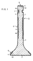
- Fig. 1 illustrates a Ti alloy poppet valve.
- a valve body 3 which comprises a valve stem 1 and a valve head 2 at the lower end is molded from Ti-Al alloy such as ⁇ phase Ti-5Al-2.5Sn alloy, ( ⁇ + ⁇ ) phase Ti-6Al-4V alloy or Ti-6Al-2Sn-4Zr-2Mo alloy made of ( ⁇ + ⁇ ) phase which contains a small amount or less than 10% ⁇ phase (Near ⁇ ).
- Ti-Al alloy such as ⁇ phase Ti-5Al-2.5Sn alloy, ( ⁇ + ⁇ ) phase Ti-6Al-4V alloy or Ti-6Al-2Sn-4Zr-2Mo alloy made of ( ⁇ + ⁇ ) phase which contains a small amount or less than 10% ⁇ phase (Near ⁇ ).
- An oxidized layer 4 which contains TiO 2 and has thickness of 10 to 15 ⁇ m is formed on the surface of parts which requires high wear resistance and fatigue strength, such as a valve face 5 which contacts a valve seat, an intermediate part 6 of the valve stem 1 which is slidably engaged in a valve guide, an annular groove 7 on which a cotter is engaged, and an end face 8 on which a rocker arm or a tappet is engaged.
- a boundary layer 4a between the oxidized layer 4 and the valve body 3 has needle crystal structure.
- the oxidized layer 4 is formed by heating the surface of said parts of the valve body 3 under oxygen atmosphere to a predetermined temperature to oxidize the surface layer.
- the oxidized layer 4 may be formed by a high frequency induction heater.
- a carburized layer 9 which contains Ti and has thickness of 3 to 5 ⁇ m is formed by carburizing on the whole surface of the valve body 3.
- the carburized layer 9 is formed by heating the surface of the valve body 3 at temperature of less than transformation point such as 800°C by a high density energy heater such as plasma, laser and electronic beam and diffusing carbons by gas carburizing.
- the high density energy heater such as plasma locally heats only the surface for a short time to prevent heat from transferring to the inside, thereby preventing changing of the material of the valve body 3 not to decrease fatigue strength. It is also advantageous in reducing carburizing time.
- the carburized layer 9 may be formed, and then the oxidized layer 4 may be formed therein.
- oxidization is carried out by an acetylene gas to diffuse carbons in the gas into the material, thereby promoting in the oxidization step.
- the valve body 3 is made of Ti-Al alloy, or ⁇ phase, ( ⁇ + ⁇ ) phase or ( ⁇ + ⁇ ) phase which contains a small amount of ⁇ phase and the carburized layer 9 is formed on the surface, so that the valve body 3 is strengthened with advantage of equiaxed structure of the valve body 3 to increase tension ductility and fatigue strength.
- fatigue strength is increased by about 20%.
- the oxidized layer 4 is formed in the parts of the valve face 5 which contacts another valve-operating member, and the boundary layer 9a therebelow is partially organized to a needle crystal structure, thereby increasing wear resistance and toughness of the surface layer significantly without decreasing fatigue strength of the whole valve body 3.
- the oxidized layer 9 is not too rigid as compared with a conventional nitriding, so that aggressiveness to another valve-operating member does not increase.
- the inventors makes samples the surface of which was treated and a wear test is carried out to the samples. A wear tester and how to examine will be described.
- Fig. 2 illustrates a Crossbar tester which comprises a motor 10, a sample fixing jig 11 which moves up and down just above the end of a shaft 10a of the motor 10 and a weight 12 on the fixing jig 11.
- a disc-shaped steel chip 13 which is ground at the outer circumferential surface and treated with oil extraction is concentrically mounted. Then, on the lower surface of the fixing jig 11, a sample 14 which is treated with oil extraction and has a flat lower end face is mounted, and the lower end face is engaged on the upper surface of the chip 13.
- a 1kg weight 12 is put on the upper surface of a fixing jig 11, and a motor 10 is operated to rotate the chip 13 at fixed speed.
- a weight is added by 500g every time the chip 13 slides on the sample 14 by 50m which is determined by rotation of the motor and an outer diameter of the chip.
- the test is finished when seizure and galling occurs between the sample 14 and the chip 13 or when sliding distance reaches to 350m. 350m.
- Fig. 3 The results of the test are shown in Fig. 3.
- the sample “A” denotes an ordinary Ti-Al alloy which is not hardened on the surface;
- “B” denotes Ti-6Al-4V alloy on which a carburized layer is formed;
- “C” denotes Ti-6Al-2Sn-4Zr-2Mo alloy on which a carburized layer is formed;
- D denotes one which has further an oxidized layer in "B”;
- E denotes one which has further an oxidized layer in "C”
- the samples "B” and “C” which have only carburized layer is better than non-hardened sample “A”, and the samples “D” and “E” which have oxidized layer on the samples “B” and “C” are greatly better.
- the sample “E”, Ti-6Al-2Sn-4Zr-2Mo has no seizure even if it slides by 350m, to provide significant high wear resistance.
- the oxidized layer 4 is formed only on parts which are engaged with another valve-operating member to form needle crystal structure, and the carburized layer 9 is formed on the whole surface of the valve body 3 to improve wear resistance and fatigue strength totally.
- wear resistance and toughness of the surface layer can be improved.
- valve body 3 is directly oxidized on the surface, but it is difficult to obtain the above oxidized layer owing to reflection rate of the surface, and treatment time must be extended. Thus, heated area increases, and needle crystal structure increases to decrease fatigue strength of the valve body.
- a carbon spray film used in a laser beam processing may be applied to the surface of the valve body 3. So formed even if the carburized layer 9 is thin.
- the present invention is not limited to the foregoing embodiments.
- the oxidized layer 4 is formed on part which contacts another valve-operating member and the lower boundary layer 4a is formed as needle crystal structure. But only the oxidized layer 4 may be formed without such needle crystal structure.
- valve body 3 is made of Ti alloy which comprises ⁇ phase, ( ⁇ + ⁇ ) phase, or ( ⁇ + ⁇ ) phase which contains a little amount of ⁇ phase, but Ti alloy which comprises ⁇ phase may be used.
Landscapes
- Chemical & Material Sciences (AREA)
- Engineering & Computer Science (AREA)
- Mechanical Engineering (AREA)
- Chemical Kinetics & Catalysis (AREA)
- Materials Engineering (AREA)
- Metallurgy (AREA)
- Organic Chemistry (AREA)
- Inorganic Chemistry (AREA)
- Ceramic Engineering (AREA)
- General Engineering & Computer Science (AREA)
- Solid-Phase Diffusion Into Metallic Material Surfaces (AREA)
- Other Surface Treatments For Metallic Materials (AREA)
Description
- The present invention relates to a Ti alloy poppet valve which provides improved wear resistance and strength, and surface treatment thereof.
- The largest difficulty for increasing allowable rotation speed of an engine is increase in inertial mass owing to increase in weight of valve-operating parts. If whole weight of the valve-operating parts increases, followability of a valve body to a cam decreases owing to inertial mass during high-speed rotation so as to decrease engine output performance.
- Therefore, a poppet valve is molded from a low-density heat resistant Ti alloy to decrease its weight instead of a conventional heat resistant steel. However, Ti alloy has activity and is likely to adhere to another metal. Wear resistance and fatigue strength are not sufficient. Surface treatment such as nitriding and Ni plating is made on the surface of Ti alloy valve to improve wear resistance.
- The nitrided valve provide high strength or hardness and wear resistance, but it is too rigid, so that it is likely to attack other parts. It is required to replace material of another valve-operating member which contacts the valve to increase manufacturing cost. A Ni plated valve does not achieve sufficient heat resistance and is not suitable as an exhaust valve.
- In view of the disadvantages, it is a primary object of the present invention to provide a Ti alloy poppet valve which improves wear resistance and strength without nitriding or plating.
- Accordingly, the invention provides a Ti alloy poppet valve as defined by claim 1.
- The features and advantages of the invention will become more apparent from the following description with respect to embodiments as shown in attached drawings wherein:
- Fig. 1 is a central vertical sectioned front view of a poppet valve according to the present invention;
- Fig. 2 is a front elevational view of a wear tester; and
- Fig. 3 is a graph which shows the results a test.
- Fig. 1 illustrates a Ti alloy poppet valve. A
valve body 3 which comprises a valve stem 1 and avalve head 2 at the lower end is molded from Ti-Al alloy such as α phase Ti-5Al-2.5Sn alloy, (α + β) phase Ti-6Al-4V alloy or Ti-6Al-2Sn-4Zr-2Mo alloy made of (α + β) phase which contains a small amount or less than 10% β phase (Near α). - An oxidized
layer 4 which contains TiO2 and has thickness of 10 to 15 µm is formed on the surface of parts which requires high wear resistance and fatigue strength, such as avalve face 5 which contacts a valve seat, an intermediate part 6 of the valve stem 1 which is slidably engaged in a valve guide, anannular groove 7 on which a cotter is engaged, and anend face 8 on which a rocker arm or a tappet is engaged. Aboundary layer 4a between the oxidizedlayer 4 and thevalve body 3 has needle crystal structure. - The oxidized
layer 4 is formed by heating the surface of said parts of thevalve body 3 under oxygen atmosphere to a predetermined temperature to oxidize the surface layer. The oxidizedlayer 4 may be formed by a high frequency induction heater. - After the oxidized
layer 4 is formed, a carburized layer 9 which contains Ti and has thickness of 3 to 5 µm is formed by carburizing on the whole surface of thevalve body 3. The carburized layer 9 is formed by heating the surface of thevalve body 3 at temperature of less than transformation point such as 800°C by a high density energy heater such as plasma, laser and electronic beam and diffusing carbons by gas carburizing. - The high density energy heater such as plasma locally heats only the surface for a short time to prevent heat from transferring to the inside, thereby preventing changing of the material of the
valve body 3 not to decrease fatigue strength. It is also advantageous in reducing carburizing time. - The carburized layer 9 may be formed, and then the oxidized
layer 4 may be formed therein. In this case, oxidization is carried out by an acetylene gas to diffuse carbons in the gas into the material, thereby promoting in the oxidization step. - As carried out by the foregoing embodiment, the
valve body 3 is made of Ti-Al alloy, or α phase, (α + β) phase or (α + β) phase which contains a small amount of β phase and the carburized layer 9 is formed on the surface, so that thevalve body 3 is strengthened with advantage of equiaxed structure of thevalve body 3 to increase tension ductility and fatigue strength. By forming only the carburized layer 9, fatigue strength is increased by about 20%. - Futhermore, the oxidized
layer 4 is formed in the parts of thevalve face 5 which contacts another valve-operating member, and the boundary layer 9a therebelow is partially organized to a needle crystal structure, thereby increasing wear resistance and toughness of the surface layer significantly without decreasing fatigue strength of thewhole valve body 3. - The oxidized layer 9 is not too rigid as compared with a conventional nitriding, so that aggressiveness to another valve-operating member does not increase.
- The inventors makes samples the surface of which was treated and a wear test is carried out to the samples. A wear tester and how to examine will be described.
- Fig. 2 illustrates a Crossbar tester which comprises a
motor 10, asample fixing jig 11 which moves up and down just above the end of ashaft 10a of themotor 10 and aweight 12 on thefixing jig 11. - At the end of the
shaft 10a, a disc-shaped steel chip 13 which is ground at the outer circumferential surface and treated with oil extraction is concentrically mounted. Then, on the lower surface of thefixing jig 11, a sample 14 which is treated with oil extraction and has a flat lower end face is mounted, and the lower end face is engaged on the upper surface of thechip 13. A1kg weight 12 is put on the upper surface of afixing jig 11, and amotor 10 is operated to rotate thechip 13 at fixed speed. A weight is added by 500g every time thechip 13 slides on the sample 14 by 50m which is determined by rotation of the motor and an outer diameter of the chip. - The test is finished when seizure and galling occurs between the sample 14 and the
chip 13 or when sliding distance reaches to 350m. 350m. - The results of the test are shown in Fig. 3. The sample "A" denotes an ordinary Ti-Al alloy which is not hardened on the surface; "B" denotes Ti-6Al-4V alloy on which a carburized layer is formed; "C" denotes Ti-6Al-2Sn-4Zr-2Mo alloy on which a carburized layer is formed; "D" denotes one which has further an oxidized layer in "B"; and "E" denotes one which has further an oxidized layer in "C"
- As shown in Fig. 3, in seizure occurrence distance, the samples "B" and "C" which have only carburized layer is better than non-hardened sample "A", and the samples "D" and "E" which have oxidized layer on the samples "B" and "C" are greatly better. Especially, the sample "E", Ti-6Al-2Sn-4Zr-2Mo, has no seizure even if it slides by 350m, to provide significant high wear resistance.
- As described above, in the present invention, the oxidized
layer 4 is formed only on parts which are engaged with another valve-operating member to form needle crystal structure, and the carburized layer 9 is formed on the whole surface of thevalve body 3 to improve wear resistance and fatigue strength totally. Thus, without decreasing fatigue strength of thevalve body 3 itself, wear resistance and toughness of the surface layer can be improved. - It is considered that the
valve body 3 is directly oxidized on the surface, but it is difficult to obtain the above oxidized layer owing to reflection rate of the surface, and treatment time must be extended. Thus, heated area increases, and needle crystal structure increases to decrease fatigue strength of the valve body. - Before oxidization, a carbon spray film used in a laser beam processing may be applied to the surface of the
valve body 3. So formed even if the carburized layer 9 is thin. - The present invention is not limited to the foregoing embodiments. In the foregoing embodiment, the oxidized
layer 4 is formed on part which contacts another valve-operating member and thelower boundary layer 4a is formed as needle crystal structure. But only the oxidizedlayer 4 may be formed without such needle crystal structure. - In the foregoing embodiments, the
valve body 3 is made of Ti alloy which comprises α phase, (α+β) phase, or (α+β) phase which contains a little amount of β phase, but Ti alloy which comprises β phase may be used. - Various modifications and changes may be made by person skilled in the art without departing from the scope of claims wherein:
Claims (5)
- A Ti alloy poppet valve which consists of a valve body (3) which comprises a valve stem (1) and a valve head (2) at an end of said valve stem, an oxidized layer (4) being formed on part (6, 7, 8) of the valve body which contacts another valve-operating member, a carburized layer (9) being formed on said oxidized layer on a surface of the valve body which requires wear resistance and fatigue strength.
- A Ti alloy poppet valve as claimed in claim 1 wherein said another valve-operating member comprises a rocker arm, a tappet, a cam, a cotter, a valve guide or a valve seat.
- A Ti alloy poppet valve as claimed in claim 1 wherein the carburized layer is formed on the whole surface of the valve body.
- A Ti alloy poppet valve as claimed in claim 1 wherein a needle crystal structure is formed under the oxidized layer.
- A Ti alloy poppet valve as claimed in claim 1 wherein said valve body is made of Ti alloy which comprises α phase, (α + β) phase or (α + β) phase which contains a small amount of β phase.
Applications Claiming Priority (4)
| Application Number | Priority Date | Filing Date | Title |
|---|---|---|---|
| JP22665299 | 1999-08-10 | ||
| JP22665299A JP4185633B2 (en) | 1999-08-10 | 1999-08-10 | Titanium alloy engine valve and surface treatment method thereof |
| JP24954999A JP2001073726A (en) | 1999-09-03 | 1999-09-03 | Titanium alloy engine valve and surface treatment method thereof |
| JP24954999 | 1999-09-03 |
Publications (2)
| Publication Number | Publication Date |
|---|---|
| EP1076112A1 EP1076112A1 (en) | 2001-02-14 |
| EP1076112B1 true EP1076112B1 (en) | 2007-05-30 |
Family
ID=26527285
Family Applications (1)
| Application Number | Title | Priority Date | Filing Date |
|---|---|---|---|
| EP19990402427 Expired - Lifetime EP1076112B1 (en) | 1999-08-10 | 1999-10-04 | Poppet valve made of titanium alloy |
Country Status (5)
| Country | Link |
|---|---|
| US (1) | US6131603A (en) |
| EP (1) | EP1076112B1 (en) |
| KR (1) | KR20010020087A (en) |
| CN (1) | CN1283759A (en) |
| DE (1) | DE69936198T2 (en) |
Families Citing this family (18)
| Publication number | Priority date | Publication date | Assignee | Title |
|---|---|---|---|---|
| JP2001234313A (en) * | 2000-02-23 | 2001-08-31 | Fuji Oozx Inc | Method of manufacturing titanium alloy engine valve |
| JP2002097914A (en) * | 2000-07-18 | 2002-04-05 | Fuji Oozx Inc | Titanium alloy engine valve and method of manufacturing the same |
| JP2003073799A (en) * | 2001-09-03 | 2003-03-12 | Fuji Oozx Inc | Surface treatment method for titanium-based materials |
| JP2003073796A (en) * | 2001-09-03 | 2003-03-12 | Fuji Oozx Inc | Surface treatment method for titanium-based materials |
| US7866343B2 (en) | 2002-12-18 | 2011-01-11 | Masco Corporation Of Indiana | Faucet |
| US7866342B2 (en) | 2002-12-18 | 2011-01-11 | Vapor Technologies, Inc. | Valve component for faucet |
| US8555921B2 (en) | 2002-12-18 | 2013-10-15 | Vapor Technologies Inc. | Faucet component with coating |
| US8220489B2 (en) | 2002-12-18 | 2012-07-17 | Vapor Technologies Inc. | Faucet with wear-resistant valve component |
| DE10340320B4 (en) * | 2003-08-29 | 2005-11-17 | Daimlerchrysler Ag | Multi-part composite valve for an internal combustion engine |
| ATE459733T1 (en) * | 2003-12-09 | 2010-03-15 | Central Res Inst Elect | METHOD FOR PRODUCING A SUBSTRATE WITH A LAYER OF CARBON-DOPED TITANIUM OXIDE |
| JP4298690B2 (en) * | 2005-09-27 | 2009-07-22 | 本田技研工業株式会社 | Engine valve and manufacturing method thereof |
| JP2010084693A (en) * | 2008-10-01 | 2010-04-15 | Aisan Ind Co Ltd | Engine valve |
| JP5512256B2 (en) * | 2009-12-24 | 2014-06-04 | 愛三工業株式会社 | Engine valve |
| CN104388865A (en) * | 2014-11-14 | 2015-03-04 | 无锡阳工机械制造有限公司 | Titanium alloy surface treatment method |
| DE102019207536A1 (en) * | 2019-05-23 | 2020-11-26 | Mahle International Gmbh | Gas exchange valve |
| CN110079754B (en) * | 2019-05-31 | 2021-03-05 | 太原理工大学 | Titanium and titanium alloy surface composite treatment method |
| DE102019209003A1 (en) * | 2019-06-19 | 2020-12-24 | Robert Bosch Gmbh | Valve for the variable throttling of a hydraulic flow with a durable, mechanical means to reduce possible valve vibrations |
| CN116428036A (en) * | 2023-03-31 | 2023-07-14 | 镇江维纳特气门科技有限公司 | A Diesel Engine Valve with Diesel Diesel Partition by Laser |
Family Cites Families (7)
| Publication number | Priority date | Publication date | Assignee | Title |
|---|---|---|---|---|
| DE3773258D1 (en) * | 1986-05-18 | 1991-10-31 | Daido Steel Co Ltd | WEAR-RESISTANT ITEMS MADE OF TITANIUM OR TITANIUM ALLOY. |
| JPS63109151A (en) * | 1986-10-27 | 1988-05-13 | Hitachi Ltd | High hardness composite material and its manufacturing method |
| WO1994002656A1 (en) * | 1992-07-16 | 1994-02-03 | Nippon Steel Corporation | Titanium alloy bar suitable for producing engine valve |
| JPH06146825A (en) * | 1992-11-04 | 1994-05-27 | Fuji Oozx Inc | Titanium engine valve |
| JPH0734815A (en) * | 1993-07-15 | 1995-02-03 | Nippon Steel Corp | Titanium alloy engine valve manufacturing method |
| JPH07310513A (en) * | 1994-05-13 | 1995-11-28 | Aisan Ind Co Ltd | Engine valve |
| US5441235A (en) * | 1994-05-20 | 1995-08-15 | Eaton Corporation | Titanium nitride coated valve and method for making |
-
1999
- 1999-10-04 EP EP19990402427 patent/EP1076112B1/en not_active Expired - Lifetime
- 1999-10-04 US US09/411,285 patent/US6131603A/en not_active Expired - Fee Related
- 1999-10-04 DE DE1999636198 patent/DE69936198T2/en not_active Expired - Lifetime
- 1999-10-12 KR KR1019990043976A patent/KR20010020087A/en not_active Withdrawn
- 1999-10-15 CN CN99121816A patent/CN1283759A/en active Pending
Also Published As
| Publication number | Publication date |
|---|---|
| US6131603A (en) | 2000-10-17 |
| DE69936198T2 (en) | 2008-01-31 |
| EP1076112A1 (en) | 2001-02-14 |
| KR20010020087A (en) | 2001-03-15 |
| CN1283759A (en) | 2001-02-14 |
| DE69936198D1 (en) | 2007-07-12 |
Similar Documents
| Publication | Publication Date | Title |
|---|---|---|
| EP1076112A1 (en) | TI alloy poppet valve and surface treatment thereof | |
| US6511045B2 (en) | Ti alloy poppet valve and a method of manufacturing the same | |
| US7246586B2 (en) | Wear-resistant coating and process for producing it | |
| JP2017523353A (en) | Brake disc for automobile | |
| KR920003630B1 (en) | Surface treatment method of titanium or titanium alloy | |
| EP0244253B1 (en) | Surface treatment of titanium articles | |
| EP1288327B1 (en) | TI alloy surface treatment | |
| JP4185633B2 (en) | Titanium alloy engine valve and surface treatment method thereof | |
| JPH0821216A (en) | Engine valve | |
| JPH07310513A (en) | Engine valve | |
| JP2001073726A (en) | Titanium alloy engine valve and surface treatment method thereof | |
| US7621244B2 (en) | Titanium alloy tappet, manufacturing method thereof, and jig used in manufacturing tappet | |
| EP0721997A1 (en) | Method of treating the surface of TI or TI alloy valve element | |
| JP2641424B2 (en) | Method for manufacturing internal combustion engine valve train | |
| JP2002115514A (en) | Aluminum alloy valve spring retainer and method of manufacturing the same | |
| JPH05306461A (en) | Wear resistant sliding member of internal combustion engine | |
| JP2812563B2 (en) | Valve lifter and method of manufacturing the same | |
| JP2004190560A (en) | piston ring | |
| JPH04171206A (en) | Valve retainer for internal combustion engine | |
| JPH03249313A (en) | Intake/discharge valve for internal combustion engine | |
| JP2001041008A (en) | Valve system for 4-cycle engine | |
| JP2003106112A (en) | Cam follower, method of manufacturing cam follower, and cam follower mechanism | |
| JP2000130113A (en) | Rush adjuster | |
| JPH04241708A (en) | Valve lifter and manufacture thereof | |
| JPH09195729A (en) | Titanium alloy poppet valve |
Legal Events
| Date | Code | Title | Description |
|---|---|---|---|
| PUAI | Public reference made under article 153(3) epc to a published international application that has entered the european phase |
Free format text: ORIGINAL CODE: 0009012 |
|
| AK | Designated contracting states |
Kind code of ref document: A1 Designated state(s): AT BE |
|
| AX | Request for extension of the european patent |
Free format text: AL;LT;LV;MK;RO;SI |
|
| 17P | Request for examination filed |
Effective date: 20010627 |
|
| AKX | Designation fees paid |
Free format text: AT BE |
|
| RBV | Designated contracting states (corrected) |
Designated state(s): DE GB |
|
| RTI1 | Title (correction) |
Free format text: POPPET VALVE MADE OF TITANIUM ALLOY |
|
| GRAP | Despatch of communication of intention to grant a patent |
Free format text: ORIGINAL CODE: EPIDOSNIGR1 |
|
| GRAS | Grant fee paid |
Free format text: ORIGINAL CODE: EPIDOSNIGR3 |
|
| GRAA | (expected) grant |
Free format text: ORIGINAL CODE: 0009210 |
|
| AK | Designated contracting states |
Kind code of ref document: B1 Designated state(s): DE GB |
|
| REG | Reference to a national code |
Ref country code: GB Ref legal event code: FG4D |
|
| REF | Corresponds to: |
Ref document number: 69936198 Country of ref document: DE Date of ref document: 20070712 Kind code of ref document: P |
|
| PLBE | No opposition filed within time limit |
Free format text: ORIGINAL CODE: 0009261 |
|
| STAA | Information on the status of an ep patent application or granted ep patent |
Free format text: STATUS: NO OPPOSITION FILED WITHIN TIME LIMIT |
|
| 26N | No opposition filed |
Effective date: 20080303 |
|
| PGFP | Annual fee paid to national office [announced via postgrant information from national office to epo] |
Ref country code: GB Payment date: 20100924 Year of fee payment: 12 |
|
| PGFP | Annual fee paid to national office [announced via postgrant information from national office to epo] |
Ref country code: DE Payment date: 20101130 Year of fee payment: 12 |
|
| GBPC | Gb: european patent ceased through non-payment of renewal fee |
Effective date: 20121004 |
|
| PG25 | Lapsed in a contracting state [announced via postgrant information from national office to epo] |
Ref country code: DE Free format text: LAPSE BECAUSE OF NON-PAYMENT OF DUE FEES Effective date: 20130501 Ref country code: GB Free format text: LAPSE BECAUSE OF NON-PAYMENT OF DUE FEES Effective date: 20121004 |
|
| REG | Reference to a national code |
Ref country code: DE Ref legal event code: R119 Ref document number: 69936198 Country of ref document: DE Effective date: 20130501 |