EP1076169A2 - Dispositif pour humidifier l'air d'admission d'un moteur à combustion turbochargé - Google Patents
Dispositif pour humidifier l'air d'admission d'un moteur à combustion turbochargé Download PDFInfo
- Publication number
- EP1076169A2 EP1076169A2 EP00117196A EP00117196A EP1076169A2 EP 1076169 A2 EP1076169 A2 EP 1076169A2 EP 00117196 A EP00117196 A EP 00117196A EP 00117196 A EP00117196 A EP 00117196A EP 1076169 A2 EP1076169 A2 EP 1076169A2
- Authority
- EP
- European Patent Office
- Prior art keywords
- air
- heat exchanger
- intake air
- internal combustion
- water
- Prior art date
- Legal status (The legal status is an assumption and is not a legal conclusion. Google has not performed a legal analysis and makes no representation as to the accuracy of the status listed.)
- Granted
Links
- 238000002485 combustion reaction Methods 0.000 title claims description 30
- 238000011144 upstream manufacturing Methods 0.000 claims abstract description 17
- XLYOFNOQVPJJNP-UHFFFAOYSA-N water Substances O XLYOFNOQVPJJNP-UHFFFAOYSA-N 0.000 claims description 44
- 150000003839 salts Chemical class 0.000 claims description 18
- 238000001816 cooling Methods 0.000 claims description 14
- 239000000498 cooling water Substances 0.000 claims description 12
- 239000013535 sea water Substances 0.000 claims description 7
- 238000010438 heat treatment Methods 0.000 claims description 6
- 239000002245 particle Substances 0.000 claims description 5
- 239000012530 fluid Substances 0.000 claims 1
- 239000007789 gas Substances 0.000 description 9
- 239000013505 freshwater Substances 0.000 description 5
- 238000009833 condensation Methods 0.000 description 4
- 230000005494 condensation Effects 0.000 description 4
- 238000007906 compression Methods 0.000 description 2
- 230000005540 biological transmission Effects 0.000 description 1
- 230000006835 compression Effects 0.000 description 1
- 239000000356 contaminant Substances 0.000 description 1
- 239000000428 dust Substances 0.000 description 1
- 238000003780 insertion Methods 0.000 description 1
- 230000037431 insertion Effects 0.000 description 1
- 239000007788 liquid Substances 0.000 description 1
- 238000000034 method Methods 0.000 description 1
- 238000002156 mixing Methods 0.000 description 1
- 239000008399 tap water Substances 0.000 description 1
- 235000020679 tap water Nutrition 0.000 description 1
Images

Classifications
-
- F—MECHANICAL ENGINEERING; LIGHTING; HEATING; WEAPONS; BLASTING
- F02—COMBUSTION ENGINES; HOT-GAS OR COMBUSTION-PRODUCT ENGINE PLANTS
- F02M—SUPPLYING COMBUSTION ENGINES IN GENERAL WITH COMBUSTIBLE MIXTURES OR CONSTITUENTS THEREOF
- F02M31/00—Apparatus for thermally treating combustion-air, fuel, or fuel-air mixture
- F02M31/02—Apparatus for thermally treating combustion-air, fuel, or fuel-air mixture for heating
- F02M31/04—Apparatus for thermally treating combustion-air, fuel, or fuel-air mixture for heating combustion-air or fuel-air mixture
- F02M31/10—Apparatus for thermally treating combustion-air, fuel, or fuel-air mixture for heating combustion-air or fuel-air mixture by hot liquids, e.g. lubricants or cooling water
-
- F—MECHANICAL ENGINEERING; LIGHTING; HEATING; WEAPONS; BLASTING
- F02—COMBUSTION ENGINES; HOT-GAS OR COMBUSTION-PRODUCT ENGINE PLANTS
- F02M—SUPPLYING COMBUSTION ENGINES IN GENERAL WITH COMBUSTIBLE MIXTURES OR CONSTITUENTS THEREOF
- F02M25/00—Engine-pertinent apparatus for adding non-fuel substances or small quantities of secondary fuel to combustion-air, main fuel or fuel-air mixture
- F02M25/022—Adding fuel and water emulsion, water or steam
- F02M25/025—Adding water
- F02M25/028—Adding water into the charge intakes
-
- F—MECHANICAL ENGINEERING; LIGHTING; HEATING; WEAPONS; BLASTING
- F02—COMBUSTION ENGINES; HOT-GAS OR COMBUSTION-PRODUCT ENGINE PLANTS
- F02M—SUPPLYING COMBUSTION ENGINES IN GENERAL WITH COMBUSTIBLE MIXTURES OR CONSTITUENTS THEREOF
- F02M31/00—Apparatus for thermally treating combustion-air, fuel, or fuel-air mixture
- F02M31/02—Apparatus for thermally treating combustion-air, fuel, or fuel-air mixture for heating
- F02M31/04—Apparatus for thermally treating combustion-air, fuel, or fuel-air mixture for heating combustion-air or fuel-air mixture
-
- F—MECHANICAL ENGINEERING; LIGHTING; HEATING; WEAPONS; BLASTING
- F02—COMBUSTION ENGINES; HOT-GAS OR COMBUSTION-PRODUCT ENGINE PLANTS
- F02B—INTERNAL-COMBUSTION PISTON ENGINES; COMBUSTION ENGINES IN GENERAL
- F02B37/00—Engines characterised by provision of pumps driven at least for part of the time by exhaust
-
- Y—GENERAL TAGGING OF NEW TECHNOLOGICAL DEVELOPMENTS; GENERAL TAGGING OF CROSS-SECTIONAL TECHNOLOGIES SPANNING OVER SEVERAL SECTIONS OF THE IPC; TECHNICAL SUBJECTS COVERED BY FORMER USPC CROSS-REFERENCE ART COLLECTIONS [XRACs] AND DIGESTS
- Y02—TECHNOLOGIES OR APPLICATIONS FOR MITIGATION OR ADAPTATION AGAINST CLIMATE CHANGE
- Y02T—CLIMATE CHANGE MITIGATION TECHNOLOGIES RELATED TO TRANSPORTATION
- Y02T10/00—Road transport of goods or passengers
- Y02T10/10—Internal combustion engine [ICE] based vehicles
- Y02T10/12—Improving ICE efficiencies
Definitions
- the present invention relates to a device for moistening the intake air of internal combustion engines, the one Have turbochargers.
- the invention has for its object a device for humidifying the intake air of an internal combustion engine with To create turbochargers with the most simple Way with a particularly low effort a NOx reduction is achievable in the exhaust gas of the internal combustion engine.
- the inlet air is thus humidified in the non-compressed state.
- the intake air is pre preheated after passing the humidifier, for what which compressed the compressor leaving the turbocharger and already humidified by the humidifier Intake air is used.
- the preheating is done with the help an air / air heat exchanger realized by the compressed Intake air is passed.
- the compressed intake air which is due both to the preheating and also been heated by the compression in the compressor gives the air / air heat exchanger part of its thermal energy on the atmospheric intake air and thus chilled. It is thus cooled compressed air Internal combustion engine supplied.
- the invention particularly relates to diesel or Gas engines, which does not preclude them from others Motors can be used.
- Humidification of the intake air in the humidifier takes place adiabatically.
- the air / air heat exchanger may be a known one and already existing in internal combustion engines Act intercooler with air cooling.
- the air in the compressor of the turbocharger through the compression process carried out to a temperature heated in a range of 150-200 ° C.
- the preheating step is the atmospheric intake air through the heated compressed air to a temperature range heated from 35-120 ° C.
- the heated is compressed Air cooled from 150-200 ° C to about 90-100 ° C.
- the heater is for the intake air an air / water heat exchanger to deliver the thermal energy of the cooling water of the internal combustion engine.
- the Air / water heat exchangers can be directly from the cooling water flow through, or there may be an additional water cycle be interposed.
- the heating device is formed by an air / air heat exchanger which for Transfer of the thermal energy of the exhaust gas of the internal combustion engine serves on the intake air.
- a water circuit interposed his.
- the compressed, leaving the air / air heat exchanger, humidified air can be introduced into the internal combustion engine be further treated, in particular cooled and / or be moistened again. Cooling is in the Usually desirable, as the one leaving the air / air heat exchanger compressed air is still too hot. That's how one looks Embodiment of the invention before that in the flow path the compressed and humidified intake air between the Air / air heat exchanger and the internal combustion engine Cooling device is switched. A normal one can do this Intercooler can be used.
- Another alternative provides that in the flow path the compressed and humidified intake air between the Air / air heat exchanger and the internal combustion engine third humidifier is connected.
- the third moistening device is preferred a heat exchanger for heating the humidification medium Assigned (water).
- This embodiment corresponds to the embodiment described in WO 95/23286, where the flow of compressed air Humidifier with heated water for humidification is applied and the heating of the water via a water / water or water / air heat exchanger takes place either from the cooling water or from the exhaust gas of the Internal combustion engine is flowed through.
- An air filter is usually upstream of the air / air heat exchanger arranged in the flow path of the intake air. To relieve the air filter, however, it can also downstream of the humidifier in the flow path of the Intake air may be provided. With this embodiment some of the contaminants are already in the humidifier dissipated.
- the device designed according to the invention takes place in particular for diesel internal combustion engines of ships, boats and the like Vehicles use.
- the diesel internal combustion engines of such vehicles often have a sea water circuit (Salt water circuit), the water of which either itself Cooling the diesel engine is used or with fresh water cooling to cool the cooling water via a Serves as a heat exchanger. If such a sea water circuit is present, the humidification device (s) expediently charged with salt water, so that no special fresh water source is required.
- the Salt water can be collected and returned to the cycle returned to the supply line leading to the humidification device become.
- the cooling device mentioned above is convenient controlled depending on the turbocharger pressure to to avoid condensation.
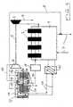
- the diesel internal combustion engine 1 shown in FIG. 1 it is a marine engine that has four cylinders 2 having.
- the exhaust gas of the internal combustion engine 1 is derived at 4 and drives a turbine 3, which is part of a turbocharger forms.
- the turbocharger also includes a compressor 6, which is driven by the turbine 3 via a shaft 5 becomes.
- the compressor 6 is used to compress the Intake air of the diesel engine, which has a 17 flow path shown the respective cylinders 2nd is fed.
- Atmospheric intake air passes through an air filter 12 to compressor 6.
- air filter 12 Located in the intake air flow path in this order from the air filter 12 to the compressor 6 an air / water heat exchanger 13, a second humidification device 14, an air / air heat exchanger 15 and a first humidifier 16.
- the inlet air passes the air / water heat exchanger 13 and is preheated.
- the preheated air is humidified, cooling it down becomes.
- the following air / air heat exchanger 15 is used reheat and in the subsequent humidifier 16 additional humidification before the intake air enters the compressor 6.
- the compressed, humidified output from the compressor 6 Air reaches the air / air heat exchanger via the flow path 17 15 where they transfer part of their thermal energy to the emits inlet air flowing through the heat exchanger.
- the compressed, cooled air leaves the heat exchanger 15 and passes into an intercooler 9, where it cools down again becomes.
- the air then becomes the cylinders 2 of the diesel engine 1 fed.
- the ship engine shown here has a sea water circuit (Salt water circuit) 7, which is used to cool the engine. From this circle 7 is salt water 8 via a branch line branched off, the two humidifiers 14 and 16 is supplied. Have the humidifiers a packed bed covered by salt water from top to bottom is flowed through, the salt water through suitable nozzles is sprayed onto the packed bed. The packed bed is traversed by the inlet air in the transverse direction, wherein absorbs this corresponding moisture.
- Salt water circuit Salt water circuit
- a device for separating entrained salt particles In the flow path 17 of the intake air can be downstream of the humidifiers a device for separating entrained salt particles must be switched on to carry along of salt particles in the cylinders of the internal combustion engine to prevent.
- a Water / water heat exchanger 10 turned on for transmission the thermal energy in the cooling water to one Water circuit 11 is used.
- This water cycle contains the above-mentioned air / water heat exchanger 13 for Preheat the intake air.
- the flowing through the circle 11 heated water flows through the coils of the Heat exchanger 13 and thereby heats the coils flowing intake air.
- the exhaust gas from the diesel engine can also be used to preheat the intake air serve.
- the heat exchanger 13 can therefore also be an air / air heat exchanger.
- Figure 2 is also a marine diesel engine 1 with four cylinders 2, which represent a turbocharger consisting of a turbine 3 operated by the exhaust gas, a compressor 6 and a shaft 5 for driving the Compressor has. Also in this embodiment the flow path of the intake air for the internal combustion engine designated 17. Otherwise designate the same reference numerals same parts as in Figure 1.
- the atmospheric intake air happens in this order up to the compressor 6 an air filter 12, a downstream one Air / air heat exchanger 15 and a downstream Humidification device 16.
- the air is preheated in the air / air heat exchanger 15 and in the humidifier 16 moistened. It is in the compressor 6 compressed, then through the heat exchanger 15 for preheating of the intake air, and finally before insertion into the internal combustion engine through a further treatment stage headed.
- the Inlet air in the humidifier 16 salt water used that via a branch line 8 from a sea water circuit (Salt water circuit) 7 is branched off.
- the embodiment is for cooling the internal combustion engine 1
- Fresh water uses a water / water heat exchanger 22 happens in it from the sea water of the sea water circuit 7 is cooled.
- the cooling water passes another heat exchanger 21, the component of the further treatment stage which is described below.
- the further treatment stage for the compressed and moisturized Inlet air has a third humidifier 20, which is designed as a lying container and also has a packed bed.
- the packed bed is flowed through by the intake air and fresh water (Co-current or cross-flow), the compressed intake air is moistened after passing the humidifier 20 the cylinders 2 of the internal combustion engine 1 is supplied.
- the water used for moistening passes from the moistening device 20 into a Storage container 23 and from there via the heat exchanger 21 back into the humidifier. In the heat exchanger 21 it is heated by the cooling water of the internal combustion engine, so that compressed in the humidifier 20 Air and heated water meet.
- FIG. 2 shows an embodiment in which the entire Water circuit is a salt water circuit, i.e. also the rest Salt water from the branch line 8 is through the heat exchanger 21 led. This means that with both humidifiers worked with salt water. Only the Cooling water circuit is a fresh water circuit.
- FIG. 2 The embodiment shown in Figure 2 is suitable for cases where a particularly strong humidification of the Intake air is desired.
- bypass line 18 which starts from the air filter 12 and in which a suitable mixing valve is provided in order to a workaround for levels 13, 14, 15 and 16 too enable.
- the bypass line 18 has one or more Branch lines on that between the stages in the main flow path the air flows out. flow out.
- Stages can be connected upstream of the heat exchanger 15.
- a particle separator for Dust, salt particles, etc. may be provided.
- the Inlet air downstream of the humidifier and upstream a further humidification device is arranged on the compressor, which is a heater for the intake air is connected upstream.
- Proposed variant between inlet and Outlet of the cooling device is a bypass line with a bypass valve to switch. This way the actual Humidity can be controlled so that no condensation takes place.
Landscapes
- Engineering & Computer Science (AREA)
- Chemical & Material Sciences (AREA)
- Combustion & Propulsion (AREA)
- Mechanical Engineering (AREA)
- General Engineering & Computer Science (AREA)
- Supercharger (AREA)
- Structures Of Non-Positive Displacement Pumps (AREA)
- Output Control And Ontrol Of Special Type Engine (AREA)
Applications Claiming Priority (2)
| Application Number | Priority Date | Filing Date | Title |
|---|---|---|---|
| DE19938292A DE19938292A1 (de) | 1999-08-12 | 1999-08-12 | Vorrichtung zur Befeuchtung der Einlaßluft von Brennkraftmaschinen mit Turbolader |
| DE19938292 | 1999-08-12 |
Publications (3)
| Publication Number | Publication Date |
|---|---|
| EP1076169A2 true EP1076169A2 (fr) | 2001-02-14 |
| EP1076169A3 EP1076169A3 (fr) | 2001-10-10 |
| EP1076169B1 EP1076169B1 (fr) | 2005-03-16 |
Family
ID=7918217
Family Applications (1)
| Application Number | Title | Priority Date | Filing Date |
|---|---|---|---|
| EP00117196A Expired - Lifetime EP1076169B1 (fr) | 1999-08-12 | 2000-08-11 | Dispositif pour humidifier l'air d'admission d'un moteur à combustion turbochargé |
Country Status (4)
| Country | Link |
|---|---|
| US (1) | US6405686B1 (fr) |
| EP (1) | EP1076169B1 (fr) |
| AT (1) | ATE291165T1 (fr) |
| DE (2) | DE19938292A1 (fr) |
Cited By (14)
| Publication number | Priority date | Publication date | Assignee | Title |
|---|---|---|---|---|
| EP1076168A2 (fr) * | 1999-08-13 | 2001-02-14 | Munters Euroform GmbH | Dispositif pour humidifier l'air d'admission de moteurs à combustion |
| EP1205659A3 (fr) * | 2000-11-03 | 2002-09-11 | Wärtsilä Technology Oy AB | Procédé de réduction des émissions NOX d'un moteur à pistons surchargé |
| WO2002075141A1 (fr) | 2001-03-20 | 2002-09-26 | Munters Euroform Gmbh | Dispositif d'humidification de l'air d'entree d'un moteur a combustion interne comportant un turbocompresseur par prechauffage au moyen d'un circuit d'eau |
| WO2003031795A1 (fr) * | 2001-10-09 | 2003-04-17 | Wärtsilä Finland Oy | Agencement et procede relatifs a un moteur diesel |
| WO2003078819A1 (fr) * | 2002-03-20 | 2003-09-25 | Wärtsilä Finland Oy | Procede visant a reduire les emissions d'oxyde d'azote (nox) dans un moteur a piston suralimente et dispositif de moteur a piston |
| DE10204181C1 (de) * | 2002-02-01 | 2003-10-09 | Man B & W Diesel Ag | Kolbenbrennkraftmaschine |
| WO2003089780A1 (fr) * | 2002-04-19 | 2003-10-30 | Marioff Corporation Oy | Procede et appareil de pulverisation |
| WO2005031144A1 (fr) * | 2003-09-24 | 2005-04-07 | Munters Euroform Gmbh | Ensemble moteur a combustion interne comprenant un dispositif d'humidification |
| WO2006034876A1 (fr) * | 2004-09-30 | 2006-04-06 | Behr Gmbh & Co. Kg | Systeme caloporteur et procede de refroidissement de l'air de suralimentation |
| WO2007115579A3 (fr) * | 2006-04-12 | 2008-06-26 | Man Diesel As | Moteur diesel à turbocompresseur de grande taille doté d'un dispositif de récupération d'énergie |
| DE102009046120A1 (de) | 2009-10-28 | 2011-05-12 | Ford Global Technologies, LLC, Dearborn | Verfahren und Vorrichtung zum Befeuchten der Ansaugluft einer Verbrennungsmaschine |
| EP2610472A4 (fr) * | 2010-08-24 | 2013-07-03 | Asahi Kasei Chemicals Corp | Procédé permettant de réduire les oxydes d'azote dans un moteur à combustion interne et appareil associé |
| DK178371B1 (da) * | 2008-09-29 | 2016-01-18 | Man Diesel & Turbo Deutschland | Stor turboladet dieselmotor med energigenvindingsindretning |
| DE102014222461A1 (de) * | 2014-11-04 | 2016-05-04 | Bayerische Motoren Werke Aktiengesellschaft | Verbrennunsmaschine, Wassereinspritzung einer Verbrennungsmaschine sowie Verfahren zum Betrieb einer Verbrennungsmaschine |
Families Citing this family (15)
| Publication number | Priority date | Publication date | Assignee | Title |
|---|---|---|---|---|
| US7007680B2 (en) * | 2003-08-07 | 2006-03-07 | Mack Trucks, Inc. | Cooler bypass valve system and method |
| FI119119B (fi) * | 2003-10-15 | 2008-07-31 | Waertsilae Finland Oy | Menetelmä ahdetun mäntämoottorin typpioksidipäästöjen (NOx) vähentämiseksi ja mäntämoottorijärjestely |
| US6935831B2 (en) * | 2003-10-31 | 2005-08-30 | General Electric Company | Methods and apparatus for operating gas turbine engines |
| US7272933B2 (en) * | 2004-01-28 | 2007-09-25 | General Electric Company | Methods and apparatus for operating gas turbine engines |
| US7051720B2 (en) * | 2004-10-01 | 2006-05-30 | Electro-Motive Diesel, Inc. | Engine with charge air-cooling system with water fumigation |
| FI119117B (fi) * | 2005-06-02 | 2008-07-31 | Waertsilae Finland Oy | Menetelmä ja järjestely turboahdetun mäntämoottorin yhteydessä |
| US9546574B2 (en) * | 2010-12-28 | 2017-01-17 | Rolls-Royce Corporation | Engine liquid injection |
| US9334791B2 (en) | 2012-09-17 | 2016-05-10 | Ford Global Technologies, Llc | Charge air cooler condensation control |
| CN103557096B (zh) * | 2013-09-24 | 2015-11-18 | 上海昌洁环保科技有限公司 | 雾流量控制箱及使用其的助燃装置、内燃机、交通工具 |
| US9879591B2 (en) * | 2015-02-20 | 2018-01-30 | Pratt & Whitney Canada Corp. | Engine intake assembly with selector valve |
| US9797297B2 (en) * | 2015-02-20 | 2017-10-24 | Pratt & Whitney Canada Corp. | Compound engine assembly with common inlet |
| US9896998B2 (en) | 2015-02-20 | 2018-02-20 | Pratt & Whitney Canada Corp. | Compound engine assembly with modulated flow |
| US9932892B2 (en) | 2015-02-20 | 2018-04-03 | Pratt & Whitney Canada Corp. | Compound engine assembly with coaxial compressor and offset turbine section |
| DE102018218871A1 (de) * | 2018-11-06 | 2020-05-07 | Ford Global Technologies, Llc | Anordnung und Verfahren zur Verringerung der Kondensatbildung in einem Zuluftstrang eines Verbrennungsmotors sowie Kraftfahrzeug |
| CN113339086B (zh) * | 2021-07-08 | 2022-05-31 | 山东大学 | 一种空气冷却加湿装置、方法及湿空气透平循环系统 |
Family Cites Families (8)
| Publication number | Priority date | Publication date | Assignee | Title |
|---|---|---|---|---|
| US4440116A (en) * | 1982-07-12 | 1984-04-03 | Schmelzer Corporation | Coolant injector |
| US4557222A (en) * | 1983-09-02 | 1985-12-10 | Nelson Herbert A | Forced humid aspiration for internal combustion engines |
| JPH0658068B2 (ja) * | 1988-12-28 | 1994-08-03 | ダイハツデイーゼル株式会社 | ディーゼル機関 |
| JPH0658058B2 (ja) * | 1990-03-13 | 1994-08-03 | ダイハツデイーゼル株式会社 | ディーゼル機関 |
| US5213086A (en) * | 1991-06-27 | 1993-05-25 | Carbco Technologies Inc. | Fuel inlet system for internal combustion engine |
| DK170217B1 (da) * | 1993-06-04 | 1995-06-26 | Man B & W Diesel Gmbh | Stor trykladet forbrændingsmotor og fremgangsmåde til drift af en køler til afkøling af en sådan motors indsugningsluft. |
| SE502452C2 (sv) * | 1994-02-25 | 1995-10-23 | Rosen | Sätt att tillföra ånga till insugsluften till en förbränningsmotor och en anordning därtill |
| DE19750181C2 (de) * | 1997-11-13 | 2000-06-21 | Munters Euroform Gmbh Carl | Vorrichtung zur Zuführung von Dampf zur Einlaßluft einer Brennkraftmaschine |
-
1999
- 1999-08-12 DE DE19938292A patent/DE19938292A1/de not_active Withdrawn
-
2000
- 2000-08-11 EP EP00117196A patent/EP1076169B1/fr not_active Expired - Lifetime
- 2000-08-11 AT AT00117196T patent/ATE291165T1/de not_active IP Right Cessation
- 2000-08-11 DE DE50009765T patent/DE50009765D1/de not_active Expired - Lifetime
- 2000-08-11 US US09/636,675 patent/US6405686B1/en not_active Expired - Fee Related
Cited By (20)
| Publication number | Priority date | Publication date | Assignee | Title |
|---|---|---|---|---|
| EP1076168A2 (fr) * | 1999-08-13 | 2001-02-14 | Munters Euroform GmbH | Dispositif pour humidifier l'air d'admission de moteurs à combustion |
| EP1205659A3 (fr) * | 2000-11-03 | 2002-09-11 | Wärtsilä Technology Oy AB | Procédé de réduction des émissions NOX d'un moteur à pistons surchargé |
| WO2002075141A1 (fr) | 2001-03-20 | 2002-09-26 | Munters Euroform Gmbh | Dispositif d'humidification de l'air d'entree d'un moteur a combustion interne comportant un turbocompresseur par prechauffage au moyen d'un circuit d'eau |
| US7013846B2 (en) | 2001-10-09 | 2006-03-21 | Wartsila Finland Oy | Arrangement and method in connection with diesel engine |
| WO2003031795A1 (fr) * | 2001-10-09 | 2003-04-17 | Wärtsilä Finland Oy | Agencement et procede relatifs a un moteur diesel |
| KR100867058B1 (ko) | 2001-10-09 | 2008-11-04 | 바르실라 핀랜드 오이 | 디젤엔진 및 그 작동방법 |
| CN100334342C (zh) * | 2001-10-09 | 2007-08-29 | 瓦特西拉芬兰有限公司 | 与柴油发动机相连的装置和方法 |
| DE10204181C1 (de) * | 2002-02-01 | 2003-10-09 | Man B & W Diesel Ag | Kolbenbrennkraftmaschine |
| US7178486B2 (en) | 2002-03-20 | 2007-02-20 | Wartsila Finland Oy | Method of reducing nitrogen oxide (NOx) emissions in supercharged piston engine and piston engine arrangement |
| WO2003078819A1 (fr) * | 2002-03-20 | 2003-09-25 | Wärtsilä Finland Oy | Procede visant a reduire les emissions d'oxyde d'azote (nox) dans un moteur a piston suralimente et dispositif de moteur a piston |
| US7225762B2 (en) | 2002-04-19 | 2007-06-05 | Marioff Corporation Oy | Spraying method and apparatus |
| WO2003089780A1 (fr) * | 2002-04-19 | 2003-10-30 | Marioff Corporation Oy | Procede et appareil de pulverisation |
| WO2005031144A1 (fr) * | 2003-09-24 | 2005-04-07 | Munters Euroform Gmbh | Ensemble moteur a combustion interne comprenant un dispositif d'humidification |
| WO2006034876A1 (fr) * | 2004-09-30 | 2006-04-06 | Behr Gmbh & Co. Kg | Systeme caloporteur et procede de refroidissement de l'air de suralimentation |
| WO2007115579A3 (fr) * | 2006-04-12 | 2008-06-26 | Man Diesel As | Moteur diesel à turbocompresseur de grande taille doté d'un dispositif de récupération d'énergie |
| DK178371B1 (da) * | 2008-09-29 | 2016-01-18 | Man Diesel & Turbo Deutschland | Stor turboladet dieselmotor med energigenvindingsindretning |
| DE102009046120A1 (de) | 2009-10-28 | 2011-05-12 | Ford Global Technologies, LLC, Dearborn | Verfahren und Vorrichtung zum Befeuchten der Ansaugluft einer Verbrennungsmaschine |
| EP2610472A4 (fr) * | 2010-08-24 | 2013-07-03 | Asahi Kasei Chemicals Corp | Procédé permettant de réduire les oxydes d'azote dans un moteur à combustion interne et appareil associé |
| DE102014222461A1 (de) * | 2014-11-04 | 2016-05-04 | Bayerische Motoren Werke Aktiengesellschaft | Verbrennunsmaschine, Wassereinspritzung einer Verbrennungsmaschine sowie Verfahren zum Betrieb einer Verbrennungsmaschine |
| DE102014222461B4 (de) * | 2014-11-04 | 2024-03-21 | Bayerische Motoren Werke Aktiengesellschaft | Verbrennungsmaschine, Wassereinspritzung einer Verbrennungsmaschine sowie Verfahren zum Betrieb einer Verbrennungsmaschine |
Also Published As
| Publication number | Publication date |
|---|---|
| EP1076169A3 (fr) | 2001-10-10 |
| ATE291165T1 (de) | 2005-04-15 |
| DE19938292A1 (de) | 2001-02-15 |
| DE50009765D1 (de) | 2005-04-21 |
| EP1076169B1 (fr) | 2005-03-16 |
| US6405686B1 (en) | 2002-06-18 |
Similar Documents
| Publication | Publication Date | Title |
|---|---|---|
| EP1076169A2 (fr) | Dispositif pour humidifier l'air d'admission d'un moteur à combustion turbochargé | |
| EP1570168B1 (fr) | Dispositif de refroidissement | |
| DE102018121044B4 (de) | Turbinenbypass für einen angetriebenen Turbolader und Verfahren des Zuführens von Abgasgasen von einem Abgaskrümmer eines Motors durch einen Turbinenbypass | |
| DE68907191T2 (de) | Verfahren und vorrichtung zum optimieren der temperatur der von einer gasturbine angesaugten luft. | |
| DE60021490T2 (de) | Verfahren und System zur Gasgemischvorbereitung | |
| DE102014201678B4 (de) | Ladeluftkühlersystem mit integrierter Aufheizeinrichtung | |
| DE60306954T2 (de) | Verbesserte vorrichtung zur thermischen regelung von der ansaugluft einer brennkraftmaschine und rückgeführtem brennkraftmaschinenabgas | |
| DE102012200562A1 (de) | Motorsystem | |
| EP1370760B1 (fr) | Dispositif d'humidification de l'air d'entree d'un moteur a combustion interne comportant un turbocompresseur par prechauffage au moyen d'un circuit d'eau | |
| EP0563520B1 (fr) | Installation de turbine à gaz | |
| DE102019206448B4 (de) | Motorsystem | |
| DE102007045347A1 (de) | Vorrichtung für die Ladeluftkühlung sowie Verfahren zur Ladeluftkühlung | |
| EP1076168A2 (fr) | Dispositif pour humidifier l'air d'admission de moteurs à combustion | |
| DE2625745B1 (de) | Dieselbrennkraftmaschinenanlage fuer schiffsantrieb | |
| DE10331187A1 (de) | Hubkolbenbrennkraftmaschine | |
| EP0592833B1 (fr) | Méthode pour refroidir ou chauffer un espace | |
| WO2005031144A1 (fr) | Ensemble moteur a combustion interne comprenant un dispositif d'humidification | |
| DE202013100932U1 (de) | Ladeluftkühlersystem mit integrierter Aufheizeinrichtung | |
| DE4441324C1 (de) | Anordnung zur Nutzung der im Rauchgas eines kohlegefeuerten Dampferzeugers enthaltenen Wärme | |
| DE102007019089A1 (de) | Abgaswärmetauscher, Abgaswärmetauschersystem, Brennkraftmotor und Verfahren zum Behandeln von Abgasen eines Brennkraftmotors | |
| DE102019206450B4 (de) | Motorsystem | |
| EP1727976B1 (fr) | Moteur a combustion interne a dispositif d'humidification et echangeur thermique | |
| DE102009017936A9 (de) | Luftführung für eine aufgeladene Brennkraftmaschine | |
| DE102020106076A1 (de) | Brennkraftmaschine mit Ansaugluftführung und Verdichter zum Verdichten von Ansaugluft und Verfahren zu deren Betrieb | |
| AT503458A1 (de) | Abgasanlage einer antriebseinheit für ein kraftfahrzeug mit abgasrückführung |
Legal Events
| Date | Code | Title | Description |
|---|---|---|---|
| PUAI | Public reference made under article 153(3) epc to a published international application that has entered the european phase |
Free format text: ORIGINAL CODE: 0009012 |
|
| AK | Designated contracting states |
Kind code of ref document: A2 Designated state(s): AT BE CH CY DE DK ES FI FR GB GR IE IT LI LU MC NL PT SE |
|
| AX | Request for extension of the european patent |
Free format text: AL;LT;LV;MK;RO;SI |
|
| PUAL | Search report despatched |
Free format text: ORIGINAL CODE: 0009013 |
|
| AK | Designated contracting states |
Kind code of ref document: A3 Designated state(s): AT BE CH CY DE DK ES FI FR GB GR IE IT LI LU MC NL PT SE |
|
| AX | Request for extension of the european patent |
Free format text: AL;LT;LV;MK;RO;SI |
|
| 17P | Request for examination filed |
Effective date: 20020403 |
|
| AKX | Designation fees paid |
Free format text: AT BE CH CY DE DK ES FI FR GB GR IE IT LI LU MC NL PT SE |
|
| 17Q | First examination report despatched |
Effective date: 20040219 |
|
| GRAP | Despatch of communication of intention to grant a patent |
Free format text: ORIGINAL CODE: EPIDOSNIGR1 |
|
| GRAS | Grant fee paid |
Free format text: ORIGINAL CODE: EPIDOSNIGR3 |
|
| GRAA | (expected) grant |
Free format text: ORIGINAL CODE: 0009210 |
|
| AK | Designated contracting states |
Kind code of ref document: B1 Designated state(s): AT BE CH CY DE DK ES FI FR GB GR IE IT LI LU MC NL PT SE |
|
| PG25 | Lapsed in a contracting state [announced via postgrant information from national office to epo] |
Ref country code: FI Free format text: LAPSE BECAUSE OF FAILURE TO SUBMIT A TRANSLATION OF THE DESCRIPTION OR TO PAY THE FEE WITHIN THE PRESCRIBED TIME-LIMIT Effective date: 20050316 Ref country code: IE Free format text: LAPSE BECAUSE OF FAILURE TO SUBMIT A TRANSLATION OF THE DESCRIPTION OR TO PAY THE FEE WITHIN THE PRESCRIBED TIME-LIMIT Effective date: 20050316 Ref country code: NL Free format text: LAPSE BECAUSE OF FAILURE TO SUBMIT A TRANSLATION OF THE DESCRIPTION OR TO PAY THE FEE WITHIN THE PRESCRIBED TIME-LIMIT Effective date: 20050316 |
|
| REG | Reference to a national code |
Ref country code: GB Ref legal event code: FG4D Free format text: NOT ENGLISH |
|
| REG | Reference to a national code |
Ref country code: CH Ref legal event code: EP |
|
| REG | Reference to a national code |
Ref country code: IE Ref legal event code: FG4D Free format text: GERMAN |
|
| REF | Corresponds to: |
Ref document number: 50009765 Country of ref document: DE Date of ref document: 20050421 Kind code of ref document: P |
|
| PG25 | Lapsed in a contracting state [announced via postgrant information from national office to epo] |
Ref country code: GR Free format text: LAPSE BECAUSE OF FAILURE TO SUBMIT A TRANSLATION OF THE DESCRIPTION OR TO PAY THE FEE WITHIN THE PRESCRIBED TIME-LIMIT Effective date: 20050616 Ref country code: DK Free format text: LAPSE BECAUSE OF FAILURE TO SUBMIT A TRANSLATION OF THE DESCRIPTION OR TO PAY THE FEE WITHIN THE PRESCRIBED TIME-LIMIT Effective date: 20050616 |
|
| PG25 | Lapsed in a contracting state [announced via postgrant information from national office to epo] |
Ref country code: ES Free format text: LAPSE BECAUSE OF FAILURE TO SUBMIT A TRANSLATION OF THE DESCRIPTION OR TO PAY THE FEE WITHIN THE PRESCRIBED TIME-LIMIT Effective date: 20050627 |
|
| GBT | Gb: translation of ep patent filed (gb section 77(6)(a)/1977) |
Effective date: 20050622 |
|
| REG | Reference to a national code |
Ref country code: CH Ref legal event code: NV Representative=s name: HEPP, WENGER & RYFFEL AG |
|
| PG25 | Lapsed in a contracting state [announced via postgrant information from national office to epo] |
Ref country code: CY Free format text: LAPSE BECAUSE OF FAILURE TO SUBMIT A TRANSLATION OF THE DESCRIPTION OR TO PAY THE FEE WITHIN THE PRESCRIBED TIME-LIMIT Effective date: 20050811 Ref country code: AT Free format text: LAPSE BECAUSE OF NON-PAYMENT OF DUE FEES Effective date: 20050811 Ref country code: LU Free format text: LAPSE BECAUSE OF NON-PAYMENT OF DUE FEES Effective date: 20050811 |
|
| PG25 | Lapsed in a contracting state [announced via postgrant information from national office to epo] |
Ref country code: MC Free format text: LAPSE BECAUSE OF NON-PAYMENT OF DUE FEES Effective date: 20050831 Ref country code: BE Free format text: LAPSE BECAUSE OF NON-PAYMENT OF DUE FEES Effective date: 20050831 |
|
| NLV1 | Nl: lapsed or annulled due to failure to fulfill the requirements of art. 29p and 29m of the patents act | ||
| PG25 | Lapsed in a contracting state [announced via postgrant information from national office to epo] |
Ref country code: PT Free format text: LAPSE BECAUSE OF FAILURE TO SUBMIT A TRANSLATION OF THE DESCRIPTION OR TO PAY THE FEE WITHIN THE PRESCRIBED TIME-LIMIT Effective date: 20050907 |
|
| REG | Reference to a national code |
Ref country code: IE Ref legal event code: FD4D |
|
| PLBE | No opposition filed within time limit |
Free format text: ORIGINAL CODE: 0009261 |
|
| STAA | Information on the status of an ep patent application or granted ep patent |
Free format text: STATUS: NO OPPOSITION FILED WITHIN TIME LIMIT |
|
| 26N | No opposition filed |
Effective date: 20051219 |
|
| ET | Fr: translation filed | ||
| BERE | Be: lapsed |
Owner name: MUNTERS EUROFORM G.M.B.H. Effective date: 20050831 |
|
| PG25 | Lapsed in a contracting state [announced via postgrant information from national office to epo] |
Ref country code: SE Free format text: LAPSE BECAUSE OF FAILURE TO SUBMIT A TRANSLATION OF THE DESCRIPTION OR TO PAY THE FEE WITHIN THE PRESCRIBED TIME-LIMIT Effective date: 20050616 |
|
| PGFP | Annual fee paid to national office [announced via postgrant information from national office to epo] |
Ref country code: GB Payment date: 20120815 Year of fee payment: 13 |
|
| PGFP | Annual fee paid to national office [announced via postgrant information from national office to epo] |
Ref country code: IT Payment date: 20120830 Year of fee payment: 13 Ref country code: DE Payment date: 20120830 Year of fee payment: 13 Ref country code: FR Payment date: 20120910 Year of fee payment: 13 |
|
| PGFP | Annual fee paid to national office [announced via postgrant information from national office to epo] |
Ref country code: CH Payment date: 20121029 Year of fee payment: 13 |
|
| REG | Reference to a national code |
Ref country code: CH Ref legal event code: PL |
|
| GBPC | Gb: european patent ceased through non-payment of renewal fee |
Effective date: 20130811 |
|
| PG25 | Lapsed in a contracting state [announced via postgrant information from national office to epo] |
Ref country code: CH Free format text: LAPSE BECAUSE OF NON-PAYMENT OF DUE FEES Effective date: 20130831 Ref country code: DE Free format text: LAPSE BECAUSE OF NON-PAYMENT OF DUE FEES Effective date: 20140301 Ref country code: LI Free format text: LAPSE BECAUSE OF NON-PAYMENT OF DUE FEES Effective date: 20130831 |
|
| REG | Reference to a national code |
Ref country code: FR Ref legal event code: ST Effective date: 20140430 |
|
| PG25 | Lapsed in a contracting state [announced via postgrant information from national office to epo] |
Ref country code: IT Free format text: LAPSE BECAUSE OF NON-PAYMENT OF DUE FEES Effective date: 20130811 |
|
| REG | Reference to a national code |
Ref country code: DE Ref legal event code: R119 Ref document number: 50009765 Country of ref document: DE Effective date: 20140301 |
|
| PG25 | Lapsed in a contracting state [announced via postgrant information from national office to epo] |
Ref country code: GB Free format text: LAPSE BECAUSE OF NON-PAYMENT OF DUE FEES Effective date: 20130811 |
|
| PG25 | Lapsed in a contracting state [announced via postgrant information from national office to epo] |
Ref country code: FR Free format text: LAPSE BECAUSE OF NON-PAYMENT OF DUE FEES Effective date: 20130902 |