EP1076181A2 - Piston creux pour machine à pistons alternatifs - Google Patents
Piston creux pour machine à pistons alternatifs Download PDFInfo
- Publication number
- EP1076181A2 EP1076181A2 EP00116900A EP00116900A EP1076181A2 EP 1076181 A2 EP1076181 A2 EP 1076181A2 EP 00116900 A EP00116900 A EP 00116900A EP 00116900 A EP00116900 A EP 00116900A EP 1076181 A2 EP1076181 A2 EP 1076181A2
- Authority
- EP
- European Patent Office
- Prior art keywords
- hollow piston
- peripheral wall
- piston
- hollow
- central pin
- Prior art date
- Legal status (The legal status is an assumption and is not a legal conclusion. Google has not performed a legal analysis and makes no representation as to the accuracy of the status listed.)
- Granted
Links
Images


Classifications
-
- F—MECHANICAL ENGINEERING; LIGHTING; HEATING; WEAPONS; BLASTING
- F01—MACHINES OR ENGINES IN GENERAL; ENGINE PLANTS IN GENERAL; STEAM ENGINES
- F01B—MACHINES OR ENGINES, IN GENERAL OR OF POSITIVE-DISPLACEMENT TYPE, e.g. STEAM ENGINES
- F01B3/00—Reciprocating-piston machines or engines with cylinder axes coaxial with, or parallel or inclined to, main shaft axis
- F01B3/0082—Details
- F01B3/0085—Pistons
-
- B—PERFORMING OPERATIONS; TRANSPORTING
- B23—MACHINE TOOLS; METAL-WORKING NOT OTHERWISE PROVIDED FOR
- B23P—METAL-WORKING NOT OTHERWISE PROVIDED FOR; COMBINED OPERATIONS; UNIVERSAL MACHINE TOOLS
- B23P15/00—Making specific metal objects by operations not covered by a single other subclass or a group in this subclass
- B23P15/10—Making specific metal objects by operations not covered by a single other subclass or a group in this subclass pistons
-
- F—MECHANICAL ENGINEERING; LIGHTING; HEATING; WEAPONS; BLASTING
- F04—POSITIVE - DISPLACEMENT MACHINES FOR LIQUIDS; PUMPS FOR LIQUIDS OR ELASTIC FLUIDS
- F04B—POSITIVE-DISPLACEMENT MACHINES FOR LIQUIDS; PUMPS
- F04B1/00—Multi-cylinder machines or pumps characterised by number or arrangement of cylinders
- F04B1/12—Multi-cylinder machines or pumps characterised by number or arrangement of cylinders having cylinder axes coaxial with, or parallel or inclined to, main shaft axis
- F04B1/122—Details or component parts, e.g. valves, sealings or lubrication means
- F04B1/124—Pistons
Definitions
- the invention relates to a hollow piston for a Piston machine according to the preamble of claim 1 or on methods of manufacturing a hollow piston.
- a hollow piston according to the preamble of claim 1 and Method of manufacturing a hollow piston according to the The preamble of claim 15 are in DE 196 20 167 C2 described.
- this prior art there is between the peripheral wall and a central pin of the hollow piston Ring cavity that is machined by deep drilling is, wherein the peripheral wall and the central pin in one piece are formed with a base portion of the hollow piston.
- the annular cavity is in the free end region of the hollow piston closed by a closure arrangement by a Cover is formed by using electron beam welding the peripheral wall and the central pin is connected.
- This previously known hollow piston is thus formed in two parts, wherein the base part with the peripheral wall and with the Center pin form a piston piece and the cover that other piston piece forms.
- a hollow piston known from WO 98/36156 for a Piston machine consists of an outer tube and a one Center pin forming inner tube, the latter the Axially penetrates the outer tube over its entire length, the is also called the base section and the ball joint part, whereby the inner tube at both ends axially in the outer tube is fixed that the outer tube one radially inward has directed indentation with which there is a taper engages the inner tube or in an annular recess of the Bordering inner tube.
- EP 0 402 623 A1 describes a piston for a piston machine described, consisting of a hollow piston, the cavity is filled by a filler according to FIG one molded into the outer surface of the hollow piston Rolling is positively fixed in the hollow piston, whereby the curl radially inward into the lateral surface of the Filler is molded in a ring.
- the Roll up in the area of a filler head the remaining, towards the base portion of the piston extending section of the filler in cross section is tapered and formed by a central pin, so that in this tapered area between the peripheral wall of the Hollow piston and the central pin there is an annular cavity. This should save material and weight.
- the invention has for its object a hollow piston according to the preamble of claim 1 so that he simple and ensuring a stable construction is inexpensive to manufacture, and a corresponding Specify manufacturing process. In addition, in Functional operation of the piston pressure losses can be avoided.
- the hollow piston according to the invention has in common that it are integrally formed, the closure arrangement through a radially inward molding of the Circumferential wall is formed. This will manufacture simplified and inexpensive because of the manufacture and Availability and use of additional piston parts not applicable and only part of the manufacturing measures be carried out.
- the hollow piston in the area the closure arrangement by molding the peripheral wall solidified and stabilized. Therefore, the hollow piston according to the invention with a lower Wall thickness can be designed, which further Material and weight can be saved.
- the shaping of the peripheral wall can be very advantageous accomplish by cold or warm curling, whereby a gentle deformation takes place and also a deformation of the indentation due to the existing material elasticity can be kept low. This also makes it more solid and more dense Achieve closure of the cavity. This is it advantageous, the curl in the sense of a complete Form constriction so that the peripheral wall, so to speak is waisted to zero, such a tail stub can protrude slightly from the face of the hollow piston.
- the center pin turns up as an axial support and stabilizing element that depending on the load direction (pressure stroke, suction stroke) can support the indentation or on the base section, which stabilizes these parts significantly.
- the base portion and the indentation can with a smaller axial thickness can be formed.
- To this Material can also be shortened and stabilized and save weight, which is reduced by the Longitudinal dimension of the hollow piston is conditioned.
- a advantageous support or connection between the The indentation and the center pin can then be achieved if the indentation against the lateral surface of the central pin is molded, whereby a tight press fit between let these parts be realized.
- the firmness of this Press fit can be further enlarged if the indentation engages behind a shoulder surface of the central pin or in an annular groove in the outer surface of the central pin engages, creating an axial positive connection is created.
- peripheral wall and the central pin by machining the ring cavity or a chipless formation of the peripheral wall and Center pin on a base section or on a To create the end wall of the hollow piston.
- the latter can be used Example done by extrusion, which means that Material structure is solidified and ultimately one sets favorable material fiber course.
- Chipless forming is not only the result of a machining deep drilling caused material loss avoided, but also when deep drilling resulting, circumferential grooves in the Inner surface of the peripheral wall and the outer surface of the center pin avoided, whereby the hollow piston a receives much greater stability.
- one can one-piece molding technically easier and perform faster.
- peripheral wall and the To form the center pin by extrusion. This will not just a simple and quick transformation reached, but in extrusion there is also an in the longitudinal direction of the piston Material fiber course, creating the peripheral wall and the Center pin a particularly large resistance moment against Bending loads get what on material and Structural compaction is based.
- peripheral wall and the Center pin also be formed in that these parts with the hollow piston made of sintered material and with which extending between the peripheral wall and the central pin Annular cavity are shaped and sintered.
- This will also not just a simple and inexpensive one Manufacturing accomplished, but it can also be the benefit be exploited that a sintered material as Sliding material is well suited, which is due to that the pores present in a sintered material Form lubricant pockets that provide good lubrication and a relatively low wear of the sliding surfaces guarantee.
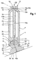
- the piston assembly generally designated 1, includes one Hollow piston 2, preferably made of steel, and one Slide shoe 3, preferably made of bronze or brass, the by a ball joint connection 1A with warranty swiveling movements limited on all sides between the Hollow piston 2 and the slide shoe 3 pivotable with each other are connected.
- the central axes of the piston 2 and Sliding shoe 3 are designated 2a and 3a.
- the articulated connection 1A has a dome-shaped or spherical segment-shaped joint recess 5 with a depth a which is larger than the radius of the sphere r one in it Swivel-mounted joint ball 4, with an equator 6 axially projecting recess edge 7 of the joint recess 5 the joint ball 4 engages behind and thereby in this Spherical ring zone convergent shape of the joint ball 4 at Maintaining a game of movement at least partially can follow.
- the axial Length b of the recess edge 7 dimensioned so long that it is in the maximum pivot position shown in Fig. 1 not hits a ball neck or the shoe body.
- the Outer lateral surface can preferably be a conical surface.
- each a channel 10a, 10b Extends longitudinally through the hollow piston 2 and the sliding block 3 each a channel 10a, 10b, which in one on the plane Foot surface 3b of the slide shoe 3 arranged flat recess 3c opens.
- the channels 10a, 10b Functional operation of the hydrostatic machine Working pressure in the hydraulic medium up to the recess 3c reproduce where the hydraulic medium has a lubrication and the pressure relieves pressure in a manner known per se causes.
- the hollow piston 2 is preferably made of hardenable steel, in particular from steel hardenable by nitriding. For the purpose of Its surface area is increased in strength and hardness preferably nitrided and hardened.
- the present ball joint connection 1A is suitable for pivotable support of a piston 2 for piston machines, in particular axial piston machines, e.g. B. on one Support surface S on which the shoe 3 with its foot surface 3b is present.
- Adjustable on an axial piston machine Throughput volume can be the support surface S inclined surface of a so-called adjustable swash plate act.
- Not adjustable on an axial piston machine Throughput volume can the joint part of the hollow piston 2 a corresponding one fixed or immovable Be articulated part of the piston machine.
- the Hollow piston 2 according to the invention are suitable for a Swashplate machine, a swashplate machine or an inclined axis machine. When using the hollow piston 2 for inclined axis machines it is advantageous to To form peripheral wall 15 conical or frustoconical, to prevent the cylinder drum from tilting avoid or take the cylinder drum with you to reach.
- the cavity 9 designed as an annular space extends from a rear base portion 11 of the hollow piston 2 to which the joint recess 5 connects to the rear, up to a front end section to the front, which by a Closure arrangement 12 for the cavity 9 is formed.
- the Cavity 9 surrounds a substantially cylindrical Center pin 13, which is in one piece from the base portion 11 extends forward. Even the hollow cylindrical one Circumferential wall 15 also extends in one piece from Base section 11 to the front.
- the peripheral wall 15 and the Center pins 13 are in one piece on the base section 11 or on Hollow piston 2 formed. This training can cutting, for example by deep drilling or non-cutting, for example by extrusion or by sintering in one Shape.
- the peripheral wall 15 and the Lock assembly 12 form a hollow cylindrical Piston shaft 2b, at its rear end a ball joint part is arranged, which in the embodiment of FIG. 1st is formed by the joint recess 5.
- piston blank 2c which is preferably with a Cross-sectional oversize X is made.
- the spherical segment-shaped joint recess 5 is preferred prefabricated with a recess edge 7, the extends axially with an inner diameter d that below Consideration of a movement game is dimensioned larger than the diameter of the joint ball 4, so that this in the Joint recess 5 is insertable.
- the closure assembly 12 is through a radially inward directed molding 16 of the peripheral wall 15 in their formed front end region.
- the peripheral wall is 15 shaped against the outer surface 13a of the center pin 13, so that the indentation 16 extends to the central pin 13 and tightly encloses it. It is advantageous to form the indentation 16 so that it with a radially inward tension against the Center pin 13 presses and thus clamps, whereby the center pin 13 in the sense of a clamp fit in the Deformation 16 is arranged and the seal improves becomes.
- the indentation 16 is so large radially inward pressure formed that also on Center pin 13 a radially inward Formation 16a is formed, whereby the The lateral surface 13a of the central pin 13 has a cross section preferably rounded annular groove 16b into which the Formation 16 with a radially inward direction Bead 16c surrounds, preferably with a radial inward clamping voltage.
- the indentation 16 will preferably by rolling up the peripheral wall 15 educated.
- the indentation 16a on the central pin 13 leads to a reduction in the cross section of the channel 10a, which differs from the end face 18 of the piston 2 continuously to the bottom the joint recess 5 extends. This Cross-section reduction can be used as a throttle.
- the indentation 16 not against the central pin 13, but against yourself molded so that the surrounded by the peripheral wall 15 Opening of the cavity 9 by molding to zero reduced and closed.
- the Center pin 13 extends to Closure arrangement 12 or for molding 16, the Formation 16 engages behind the central pin 13 and thereby the free end of which is fixed radially.
- the Recess edge 7 by means of a suitable heating device, for example in the form of a hint shown Heating ring 23, approximately on its axial length b, on a Temperature warmed to the hardness of the material is reduced so that even after the material has cooled the recess edge 7 with lower deformation forces can be cold flanged. Or the recess edge 7 can be heated to a temperature at which the strength of the material is reduced and the recess edge 7 can be hot flanged. In both cases, the Recessing edge 7 plastically in with relatively low forces that shown in Fig. 1, the joint ball 4 form-fitting Flare behind shape.
- a suitable heating device for example in the form of a hint shown Heating ring 23, approximately on its axial length b, on a Temperature warmed to the hardness of the material is reduced so that even after the material has cooled the recess edge 7 with lower deformation forces can be cold flanged.
- the recess edge 7 can be heated to a temperature at which the strength of the material
- the relatively low deformation forces sure that the recess edge 7 without a mechanical Overloading of, for example, from softer material existing sliding block 3 is deformed.
- the heating can be done by direct heating for example by means of a flame or inductively by an inductive electric heater. Through the local Heating the recess edge 7 is in this area hardened material soft again and it can therefore be light be deformed without the remaining area of the piston 2 suffered significant losses in hardness.
- a major advantage of this method of connecting the Hollow piston 2 with the slide shoe 3 is that the Hollow piston 2 before joining and connecting with the Slide shoe 3 can be completely edited without in the case of the heating described above, special measures in With regard to flanging would be required, such as Example covering the recess edge 7 to be deformed when nitriding, especially gas nitriding, turning off already nitrided areas before flaring, etc. Fine-tune the heating, flanging and cooling processes can the optimal game of the ball joint 1 very simply set and also safe in series production be reproduced.
- the arrangement of the center pin 13 leads to one essential stabilization of the hollow piston 2 and not only in terms of bending stresses but in terms of axial Compressive stresses, which the hollow piston 2 in particular is subjected to a pressure stroke in which one through the Arrow 25 shows pressure against its front Work surface at its free end that acts from Sliding shoe 3 is included in the articulation 1A.
- the one indicated by arrow 27 becomes the same size and opposing resistance in the hollow piston 2 initiated against the base section 3.
- the Base section 3 and the front end wall 12a are thus the parts of the Hollow piston 2.
- the Center pin 13 an axially effective support or Connecting part, which in the effectiveness of Compression forces 25, 27 the compressive stress on the Base section 3 and the lid or end wall 12a distributed so that these parts with a lower Compressive stress are applied. Therefore, the Base section 3 and / or the end wall 12a with a smaller axial dimension, that is, thinner become. Consequently, the hollow piston 2 or one this hollow piston 2 having piston machine, in particular Axial piston machine, with a correspondingly shorter one Execute dimension.
- the support and stabilization effect is comparable Center pin 13 also during a suction stroke of the hollow piston 2 from, directed against the pressure forces 25, 27 Tensile forces are effective on it. These tensile forces too through the center pin 13 on both the cover 12 and distributed on the base section 13 and thereby in their Impact reduced.
- the support and stabilization function of the center pin 13 is already met when the central pin 13 is extends in one piece to the indentation 16.
- the support and Stabilizing function of the center pin 13 is already met when the central pin 13 is extends in one piece to the indentation 16.
- the support and Stabilizing function of the center pin 13 on a Compressive stress limited during a pressure stroke because it is lacking Connection with the indentation 16 only compressive stresses able to forward. In the presence of tensile stresses such a center pin 13 would be ineffective.
- a central pin 13 can Ensure the functionality of the piston machine because the Risk of overloading only one Pressure stroke exists.
- the hollow piston 2 can be formed after the molding 16 be shortened to such an extent that its front end face 18a in middle region of the indentation 16 ends, the End face 18a with sloping cones forming a truncated cone Flanks can be formed within the Formation 16 run. This measure will be cutting for example by turning off. Even after this Shortening, the indentation 16 engages behind the central pin 13 in the area of the remaining section of the annular groove 16b form-fitting.
- the indentation 16 in places or to the extent mentioned and the center pin 13 may be connected to each other, e.g. B. by soldering or welding.
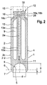
- Fig. 3 shows a reversal of the ball joint parts, wherein the ball head 4 on the hollow piston 2 and the joint recess 5 is formed on the shoe 3 and the recess edge 7 on Sliding shoe 3 hot or cold beaded accordingly becomes.
- the embodiment of the hollow piston 2 of FIG. 4, at the same or comparable parts with the same Reference numerals are different from those above-described embodiments in that the Center pin 13 and an associated channel 10a are missing and Deformation 16 by a zero-molded waist is formed so that the peripheral wall 15 z. B. with her Inner surface in the area of the waist 16d to a point is compressed, resulting in a tight seal results. At this point, the peripheral wall 15 on the Front 18a be firmly connected, for. B. by soldering or Welding. This connection point is designated 16e.
- a manufacturing method of the hollow piston 2 this Embodiment differs from that above-described manufacturing process in that only the Circumferential wall 15 machined or non-cutting on the base section 11 formed, in particular molded, and the Closure arrangement 12 executed in the sense described above becomes. Otherwise, the above-described manufacturing process features apply also for this embodiment.
- the Joint part and an associated slide shoe 3 can also 3 are formed and manufactured.
- the hollow piston 2 corresponds to the formation of the front end region of the Piston shaft 2b of the exemplary embodiment according to FIG. 4.
- the hollow piston 2 is without in the rear end region a base portion 11 forming a transverse wall and in addition, the ball joint part is in one piece without cutting molded.
- the Hollow piston 2 from a peripheral wall 15 and the transverse dimensions of which correspond to the pipe section 15a formed, as shown in Fig. 5 in dash-dotted lines.
- the indentation 16 it is also possible to form the indentation 16 so that the free Edge region of the pipe section 15a on the wall of the Ball head 4 inwards towards the inner volume 4b molded edge piece 15c results.
- the compressed Circumferential wall sections at the point connection point 16e also to connect z. B. by soldering or welding.
- An advantageous manufacturing process for the hollow piston 2 5 is that the closure assembly 12th and / or the joint part at the same time or in succession a piece of pipe 15a is formed in one piece and without cutting, preferably by curling up.
- An associated slide shoe is not shown in Fig. 5.
- the hollow piston 2 has a central pin 13 on the one piece with a front end wall 31 of the Closure arrangement 12 of the hollow piston 2 is formed, the peripheral wall 15 also integrally with the end wall 31 is formed.
- the peripheral wall 15 also integrally with the end wall 31 is formed.
- the rear end portion of the piston skirt 2b inclusive the ball joint part is in the sense of the design Fig. 5 formed. It is namely the one-piece joint part from the peripheral wall 15 forming the piston skirt 2b formed an indentation 16, the central pin 13 itself extends into the cavity 9b of the ball joint part and the indentation 16 is molded against the central pin 13 is.
- this indentation 16 may be in more detail formed according to the indentation 16 of FIGS. 1 to 3 be on in order to avoid repetitions in full Scope is referred to as it is with the same Reference details provided further details of these Show indentation.
- the end pieces 15c can instead of axially also be directed axially outwards.
- the one-piece design of the peripheral wall 15 and Center pin 13 with the end wall 31 can be chipping, z. B. by deep drilling from the back end of a corresponding Piston blanks here or by chipless molding to the End wall 31 take place.
- Advantageous manufacturing measures for the latter case z. B. a preferred simultaneous extrusion of the peripheral wall 15 and the Center pin 13 from a blank, the rest of which End wall 31 forms.
- a cold extrusion or Hot extrusion are used.
- the end wall 31 with the peripheral wall 15 and the center pin 13 by sintering in a corresponding sintering mold to be made in one piece.
- the Circumferential wall 15 is formed into a greater length than the length of the center pin 13, as shown in FIG. 6, by one sufficient length for molding the joint part, here the Ball head 4, available.
- center pin 13 as Hollow pin or sleeve can be shaped so that a Machining drilling of the channel 10a is omitted, whereby a manufacturing is further simplified.
- the hollow piston 2 is initially made with an oversize X. with its piston skirt 2b after molding, especially after hardening of its lateral surface 2d can be finished, preferably by grinding.
- This also applies to that formed by a spherical head 4 Joint part, which is also prefabricated with an oversize X. can be and after molding and preferably also after a hardening can be finished.
Landscapes
- Engineering & Computer Science (AREA)
- Mechanical Engineering (AREA)
- General Engineering & Computer Science (AREA)
- Pistons, Piston Rings, And Cylinders (AREA)
- Compressor (AREA)
Priority Applications (1)
| Application Number | Priority Date | Filing Date | Title |
|---|---|---|---|
| EP03019918A EP1378628B1 (fr) | 1999-08-12 | 2000-08-04 | Piston creux pour machine à piston et procédé pour fabriquer un piston creux |
Applications Claiming Priority (2)
| Application Number | Priority Date | Filing Date | Title |
|---|---|---|---|
| DE19938046A DE19938046A1 (de) | 1999-08-12 | 1999-08-12 | Hohlkolben für eine Kolbenmaschine und Verfahren zum Herstellen eines Hohlkolbens |
| DE19938046 | 1999-08-12 |
Related Child Applications (2)
| Application Number | Title | Priority Date | Filing Date |
|---|---|---|---|
| EP03019918A Division EP1378628B1 (fr) | 1999-08-12 | 2000-08-04 | Piston creux pour machine à piston et procédé pour fabriquer un piston creux |
| EP03019918.6 Division-Into | 2003-09-02 |
Publications (3)
| Publication Number | Publication Date |
|---|---|
| EP1076181A2 true EP1076181A2 (fr) | 2001-02-14 |
| EP1076181A3 EP1076181A3 (fr) | 2002-06-19 |
| EP1076181B1 EP1076181B1 (fr) | 2004-06-09 |
Family
ID=7918047
Family Applications (2)
| Application Number | Title | Priority Date | Filing Date |
|---|---|---|---|
| EP00116900A Expired - Lifetime EP1076181B1 (fr) | 1999-08-12 | 2000-08-04 | Piston creux pour machine à pistons alternatifs |
| EP03019918A Expired - Lifetime EP1378628B1 (fr) | 1999-08-12 | 2000-08-04 | Piston creux pour machine à piston et procédé pour fabriquer un piston creux |
Family Applications After (1)
| Application Number | Title | Priority Date | Filing Date |
|---|---|---|---|
| EP03019918A Expired - Lifetime EP1378628B1 (fr) | 1999-08-12 | 2000-08-04 | Piston creux pour machine à piston et procédé pour fabriquer un piston creux |
Country Status (2)
| Country | Link |
|---|---|
| EP (2) | EP1076181B1 (fr) |
| DE (3) | DE19938046A1 (fr) |
Cited By (3)
| Publication number | Priority date | Publication date | Assignee | Title |
|---|---|---|---|---|
| WO2008074499A1 (fr) * | 2006-12-19 | 2008-06-26 | Robert Bosch Gmbh | Piston creux pour une machine à pistons axiaux |
| CN113878086A (zh) * | 2021-10-08 | 2022-01-04 | 江苏龙城精锻集团有限公司 | 一种高压柱塞泵中空柱塞锻件及其二步成形工艺和模具 |
| CN113878085A (zh) * | 2021-10-08 | 2022-01-04 | 江苏龙城精锻集团有限公司 | 一种高压柱塞泵中空柱塞锻件及其一步成形工艺和模具 |
Families Citing this family (6)
| Publication number | Priority date | Publication date | Assignee | Title |
|---|---|---|---|---|
| DE10305136A1 (de) | 2003-02-07 | 2004-08-26 | Brueninghaus Hydromatik Gmbh | Hohlkolben für eine Kolbenmaschine und Verfahren zum Herstellen eines Hohlkolbens |
| DE10341791B4 (de) | 2003-09-10 | 2005-09-29 | Brueninghaus Hydromatik Gmbh | Hohlkolben für eine Kolbenmaschine und Verfahren zum Herstellen eines Hohlkolbens |
| DE102009056903A1 (de) | 2009-12-03 | 2011-06-09 | Danfoss A/S | Hydraulische Kolbenmaschine, insbesondere wasserhydraulische Maschine |
| CN106271416B (zh) * | 2016-08-24 | 2019-05-21 | 成都飞机工业(集团)有限责任公司 | 一种接头类零件加工方法 |
| DE102017119967A1 (de) * | 2017-08-31 | 2019-02-28 | Schaeffler Technologies AG & Co. KG | Herstellungsverfahren, Kolbenrohling, Kolben sowie Axialkolbenmaschine mit dem Kolben |
| CN109531158B (zh) * | 2018-11-28 | 2021-03-23 | 中国航发沈阳黎明航空发动机有限责任公司 | 用于航空发动机加力燃油总管的异型接头一体化加工方法 |
Family Cites Families (8)
| Publication number | Priority date | Publication date | Assignee | Title |
|---|---|---|---|---|
| GB1414037A (en) * | 1973-12-20 | 1975-11-12 | Sundstrand Corp | Light weight pistons |
| DE2647138A1 (de) * | 1976-10-19 | 1978-04-20 | Linde Ag | Kolben mit gleitschuh fuer eine hydrostatische kolbenmaschine |
| DE3406782A1 (de) * | 1983-02-25 | 1984-08-30 | Linde Ag, 6200 Wiesbaden | Kolben fuer eine hydrostatische maschine |
| DE3804424C1 (en) * | 1988-02-12 | 1989-08-24 | Hydromatik Gmbh, 7915 Elchingen, De | Piston for axial-piston machines |
| DE3912213C1 (fr) * | 1989-04-13 | 1990-10-04 | Hydromatik Gmbh, 7915 Elchingen, De | |
| DE3919329C1 (fr) * | 1989-06-13 | 1990-12-06 | Hydromatik Gmbh, 7915 Elchingen, De | |
| DE19620167C2 (de) * | 1996-05-20 | 1998-11-12 | Brueninghaus Hydromatik Gmbh | Hohlkolben mit radial verschweißtem Deckel |
| DE19706075C2 (de) * | 1997-02-17 | 2001-05-17 | Brueninghaus Hydromatik Gmbh | Kolben für eine hydrostatische Maschine |
-
1999
- 1999-08-12 DE DE19938046A patent/DE19938046A1/de not_active Ceased
-
2000
- 2000-08-04 DE DE50011401T patent/DE50011401D1/de not_active Expired - Lifetime
- 2000-08-04 EP EP00116900A patent/EP1076181B1/fr not_active Expired - Lifetime
- 2000-08-04 EP EP03019918A patent/EP1378628B1/fr not_active Expired - Lifetime
- 2000-08-04 DE DE50006731T patent/DE50006731D1/de not_active Expired - Lifetime
Cited By (5)
| Publication number | Priority date | Publication date | Assignee | Title |
|---|---|---|---|---|
| WO2008074499A1 (fr) * | 2006-12-19 | 2008-06-26 | Robert Bosch Gmbh | Piston creux pour une machine à pistons axiaux |
| CN113878086A (zh) * | 2021-10-08 | 2022-01-04 | 江苏龙城精锻集团有限公司 | 一种高压柱塞泵中空柱塞锻件及其二步成形工艺和模具 |
| CN113878085A (zh) * | 2021-10-08 | 2022-01-04 | 江苏龙城精锻集团有限公司 | 一种高压柱塞泵中空柱塞锻件及其一步成形工艺和模具 |
| CN113878086B (zh) * | 2021-10-08 | 2024-04-26 | 江苏龙城精锻集团有限公司 | 一种高压柱塞泵中空柱塞锻件及其二步成形工艺和模具 |
| CN113878085B (zh) * | 2021-10-08 | 2024-04-26 | 江苏龙城精锻集团有限公司 | 一种高压柱塞泵中空柱塞锻件及其一步成形工艺和模具 |
Also Published As
| Publication number | Publication date |
|---|---|
| EP1076181B1 (fr) | 2004-06-09 |
| DE50011401D1 (de) | 2006-03-02 |
| DE19938046A1 (de) | 2001-03-08 |
| EP1378628B1 (fr) | 2005-10-19 |
| EP1076181A3 (fr) | 2002-06-19 |
| EP1378628A1 (fr) | 2004-01-07 |
| DE50006731D1 (de) | 2004-07-15 |
Similar Documents
| Publication | Publication Date | Title |
|---|---|---|
| EP0970291B1 (fr) | Procede de production d'une articulation a joint spherique | |
| DE60113176T2 (de) | Verfahren und Maschine zur Herstellung eines Hohlkolbens für einen Kompressor durch Schmieden | |
| EP1198325B1 (fr) | Piston creux pour machine a piston et procede pour fabriquer un piston creux | |
| EP1076181B1 (fr) | Piston creux pour machine à pistons alternatifs | |
| DE3106457C2 (de) | Verfahren zum Herstellen einer Nockenwelle oder dergleichen, und Vorrichtung zur Durchführung eines solchen Verfahrens | |
| EP1664488B1 (fr) | Piston creux destine a une machine a pistons et procede de fabrication d'un piston creux | |
| DE1750662B2 (de) | Verfahren zum herstellen eines becherfoermigen kolbens | |
| DE10356111B4 (de) | Kaltumformverfahren zur Herstellung von einteiligen Kugelzapfen | |
| DE2458291A1 (de) | Schmiedeverfahren | |
| DE10219195C1 (de) | Einstückig ausgebildeter Nocken | |
| DE10142805A1 (de) | Einteiliger Gelenkkörper | |
| DE19934218C2 (de) | Verfahren zum Herstellen einer Kugelgelenkverbindung zwischen einem Gleitschuh und einem Kolben und Axialkolbenmaschine mit einer Kugelgelenkverbindung | |
| EP1248906B1 (fr) | Ensemble a piston pour machine a piston | |
| DE3004024C2 (de) | Werkzeug zum Herstellen eines Gelenkkörpers | |
| EP2148752B1 (fr) | Procédé de fabrication d'élément de base d'arbre creux | |
| DE3034951A1 (de) | Verfahren zum spanlosen herstellen einer lagerbuechse | |
| DE19903684B4 (de) | Werkzeug zum Querfließpressen | |
| WO2013121328A1 (fr) | Pièce façonnée en forme de douille et procédé ainsi que dispositif pour sa fabrication | |
| DE2542634A1 (de) | Einstueckige, hohle walzenwelle | |
| DE205996C (fr) | ||
| DE4418922A1 (de) | Verfahren und Vorrichtung zum Schmieden eines Werkstücks aus Stahl, insbesondere eines Polrades | |
| DE7014865U (de) | Vorrichtung zur Herstellung eines Rohrkörpers, insbesondere eines Ventilkörpergehäuses |
Legal Events
| Date | Code | Title | Description |
|---|---|---|---|
| PUAI | Public reference made under article 153(3) epc to a published international application that has entered the european phase |
Free format text: ORIGINAL CODE: 0009012 |
|
| AK | Designated contracting states |
Kind code of ref document: A2 Designated state(s): AT BE CH CY DE DK ES FI FR GB GR IE IT LI LU MC NL PT SE |
|
| AX | Request for extension of the european patent |
Free format text: AL;LT;LV;MK;RO;SI |
|
| PUAL | Search report despatched |
Free format text: ORIGINAL CODE: 0009013 |
|
| AK | Designated contracting states |
Kind code of ref document: A3 Designated state(s): AT BE CH CY DE DK ES FI FR GB GR IE IT LI LU MC NL PT SE |
|
| AX | Request for extension of the european patent |
Free format text: AL;LT;LV;MK;RO;SI |
|
| 17P | Request for examination filed |
Effective date: 20020708 |
|
| 17Q | First examination report despatched |
Effective date: 20021212 |
|
| AKX | Designation fees paid |
Designated state(s): DE FR GB IT SE |
|
| GRAP | Despatch of communication of intention to grant a patent |
Free format text: ORIGINAL CODE: EPIDOSNIGR1 |
|
| GRAS | Grant fee paid |
Free format text: ORIGINAL CODE: EPIDOSNIGR3 |
|
| GRAA | (expected) grant |
Free format text: ORIGINAL CODE: 0009210 |
|
| AK | Designated contracting states |
Kind code of ref document: B1 Designated state(s): DE FR GB IT SE |
|
| REG | Reference to a national code |
Ref country code: GB Ref legal event code: FG4D Free format text: NOT ENGLISH |
|
| GBT | Gb: translation of ep patent filed (gb section 77(6)(a)/1977) |
Effective date: 20040609 |
|
| REF | Corresponds to: |
Ref document number: 50006731 Country of ref document: DE Date of ref document: 20040715 Kind code of ref document: P |
|
| REG | Reference to a national code |
Ref country code: IE Ref legal event code: FG4D Free format text: GERMAN |
|
| REG | Reference to a national code |
Ref country code: SE Ref legal event code: TRGR |
|
| ET | Fr: translation filed | ||
| REG | Reference to a national code |
Ref country code: IE Ref legal event code: FD4D |
|
| PLBE | No opposition filed within time limit |
Free format text: ORIGINAL CODE: 0009261 |
|
| STAA | Information on the status of an ep patent application or granted ep patent |
Free format text: STATUS: NO OPPOSITION FILED WITHIN TIME LIMIT |
|
| 26N | No opposition filed |
Effective date: 20050310 |
|
| PGFP | Annual fee paid to national office [announced via postgrant information from national office to epo] |
Ref country code: SE Payment date: 20110823 Year of fee payment: 12 Ref country code: GB Payment date: 20110824 Year of fee payment: 12 Ref country code: FR Payment date: 20110829 Year of fee payment: 12 |
|
| PGFP | Annual fee paid to national office [announced via postgrant information from national office to epo] |
Ref country code: IT Payment date: 20110825 Year of fee payment: 12 |
|
| PGFP | Annual fee paid to national office [announced via postgrant information from national office to epo] |
Ref country code: DE Payment date: 20121024 Year of fee payment: 13 |
|
| REG | Reference to a national code |
Ref country code: SE Ref legal event code: EUG |
|
| GBPC | Gb: european patent ceased through non-payment of renewal fee |
Effective date: 20120804 |
|
| PG25 | Lapsed in a contracting state [announced via postgrant information from national office to epo] |
Ref country code: SE Free format text: LAPSE BECAUSE OF NON-PAYMENT OF DUE FEES Effective date: 20120805 |
|
| REG | Reference to a national code |
Ref country code: FR Ref legal event code: ST Effective date: 20130430 |
|
| PG25 | Lapsed in a contracting state [announced via postgrant information from national office to epo] |
Ref country code: IT Free format text: LAPSE BECAUSE OF NON-PAYMENT OF DUE FEES Effective date: 20120804 |
|
| PG25 | Lapsed in a contracting state [announced via postgrant information from national office to epo] |
Ref country code: GB Free format text: LAPSE BECAUSE OF NON-PAYMENT OF DUE FEES Effective date: 20120804 |
|
| PG25 | Lapsed in a contracting state [announced via postgrant information from national office to epo] |
Ref country code: FR Free format text: LAPSE BECAUSE OF NON-PAYMENT OF DUE FEES Effective date: 20120831 |
|
| PG25 | Lapsed in a contracting state [announced via postgrant information from national office to epo] |
Ref country code: DE Free format text: LAPSE BECAUSE OF NON-PAYMENT OF DUE FEES Effective date: 20140301 |
|
| REG | Reference to a national code |
Ref country code: DE Ref legal event code: R119 Ref document number: 50006731 Country of ref document: DE Effective date: 20140301 |