EP1076231B1 - Dispositif et méthode pour déterminer le deséquilibrage - Google Patents
Dispositif et méthode pour déterminer le deséquilibrage Download PDFInfo
- Publication number
- EP1076231B1 EP1076231B1 EP00114139.9A EP00114139A EP1076231B1 EP 1076231 B1 EP1076231 B1 EP 1076231B1 EP 00114139 A EP00114139 A EP 00114139A EP 1076231 B1 EP1076231 B1 EP 1076231B1
- Authority
- EP
- European Patent Office
- Prior art keywords
- plate
- plane
- web
- axis
- unbalance
- Prior art date
- Legal status (The legal status is an assumption and is not a legal conclusion. Google has not performed a legal analysis and makes no representation as to the accuracy of the status listed.)
- Expired - Lifetime
Links
- 238000000034 method Methods 0.000 title description 3
- 230000008878 coupling Effects 0.000 claims description 4
- 238000010168 coupling process Methods 0.000 claims description 4
- 238000005859 coupling reaction Methods 0.000 claims description 4
- 230000001747 exhibiting effect Effects 0.000 claims 1
- 230000003068 static effect Effects 0.000 description 11
- 238000005259 measurement Methods 0.000 description 7
- 238000013461 design Methods 0.000 description 5
- 238000009826 distribution Methods 0.000 description 4
- 238000000926 separation method Methods 0.000 description 3
- 238000004519 manufacturing process Methods 0.000 description 2
- 230000010355 oscillation Effects 0.000 description 2
- 230000003534 oscillatory effect Effects 0.000 description 2
- 238000005452 bending Methods 0.000 description 1
- 238000005266 casting Methods 0.000 description 1
- 238000006243 chemical reaction Methods 0.000 description 1
- 238000010276 construction Methods 0.000 description 1
- 238000001514 detection method Methods 0.000 description 1
- 238000011161 development Methods 0.000 description 1
- 238000010586 diagram Methods 0.000 description 1
- 238000006073 displacement reaction Methods 0.000 description 1
- 230000005520 electrodynamics Effects 0.000 description 1
- 238000011156 evaluation Methods 0.000 description 1
- 230000005484 gravity Effects 0.000 description 1
- 239000000463 material Substances 0.000 description 1
- 239000002184 metal Substances 0.000 description 1
- 239000000725 suspension Substances 0.000 description 1
Images


Classifications
-
- G—PHYSICS
- G01—MEASURING; TESTING
- G01M—TESTING STATIC OR DYNAMIC BALANCE OF MACHINES OR STRUCTURES; TESTING OF STRUCTURES OR APPARATUS, NOT OTHERWISE PROVIDED FOR
- G01M1/00—Testing static or dynamic balance of machines or structures
- G01M1/02—Details of balancing machines or devices
- G01M1/04—Adaptation of bearing support assemblies for receiving the body to be tested
Definitions
- the invention relates to a device for determining the imbalance of a rotating body rotatably supported by a recording with a right angle to the axis of rotation arranged, the recording having, plate-shaped dynamometer element comprising an inner via webs connected to an outer frame member receiving plate and at least one between receiving plate and Frame member arranged vibration sensor which detects unbalance induced vibrations of the receiving plate relative to the frame member, web pairs are provided on both sides of the receptacle arranged webs, as well as a method for determining the imbalance of a rotating body, which is rotatably held by a recording of an unbalance detection device, with a recording having plate-shaped dynamometer element, in which the unbalance induced vibrations of Dynamometer Symposium Seten as translational vibrations and torsional vibrations are detected separately.
- a balancing machine which has a plate-shaped dynamometer element which is partially resiliently slotted and provided with webs.
- the inner plate has a receptacle for the rotary body, which is designed as a balancing spindle.
- the receiving plate is connected to both sides of the axis of the body of revolution in the plane of the plate arranged webs with the outer frame part of the dynamometer.
- the receiving plate is the vibrations resulting from the rotation of the rotating body vibration transducer on, of which one detects only the pivoting movement of the receiving plate about an axis corresponding to the imbalance component, which arises as a result of an unbalanced moment.
- an imbalance component resulting from an individual force is picked up by a further vibration converter whose measuring direction runs parallel to the plate plane.
- the dynamometer element is supported against a foundation.
- To support two flexible elastic flat springs and a further flexible elastic support are provided.
- the flat springs for absorbing forces in the direction of the axis of rotation are attached to both sides of the axis of the body of revolution on the receiving plate and extend at right angles away from the plate surface.
- In the known device are separate elements in the form of flexurally elastic supports for receiving forces acting in the axial direction, such.
- Axialschub- or weight forces provided, which can affect the oscillatory movements of the receiving plate and thus the accuracy of the unbalance determination in an undesirable manner.
- US 4,930,348 A is a vertical, hard-sprung balancing machine with a mounted on a machine table suspension cartridge known which has two spaced-apart spring plates which receive in bores the spindle housing of a balancing spindle.
- the spring plates have concentric slots to their holes, which are separated by two diametrically arranged resilient webs.
- the resilient webs of the two spring plates lie in the same plane containing the axis of rotation of the spindle.
- a force sensor is arranged to measure vibrations in the plate plane.
- the vibration signals of both force sensors by a static imbalance and an unbalance moment induced vibrations.
- the invention is therefore based on the object, a simple and inexpensive device for determining the imbalance of a To provide a rotating body that allows a disturbance free unbalance measurement and accurate evaluation of imbalance due to unbalance and static imbalance and in particular improves the accuracy in determining the static imbalance.
- the plate-shaped dynamometer element captures all the forces and moments emanating from the rotation body in itself, so that separate supports can be omitted in an advantageous manner.
- a device with a particularly compact design or height is obtained, which has a substantially symmetrical structure with regard to the stiffness distribution and the mass distribution and which, moreover, has one ensures particularly accurate unbalance determination due to improved level separation.
- the plate-shaped dynamometer element is particularly inexpensive, for example, as a sheet metal part by burning and forming or produced as a casting.
- the design according to the invention allows a very small distance of the rotor center of gravity from the reference plane of the dynamometer element, ie ultimately a more accurate result due to improved plane separation.
- the determination of the static imbalance is very accurate, since the structure is substantially symmetrical and the measurement plane of the vibration sensor is located in the plane of the plate of the dynamometer element.
- the embodiment according to the invention is particularly advantageous for the single-plane balancing.
- the pivot axis for the torsional vibrations of the dynamometer element is optimally positioned.
- the pivot axis formed by this pair of webs lies in the plane of the plate, so that no disturbing forces or moments can influence the measurement result.
- This pair of webs takes over by its rigid configuration in the simplest way, the support not unbalanced forces such as the weight or the forces, for example, in the axial direction of the rotating body due to the design of the rotor with axial force generating elements, such as rotor blades arise.
- the webs of this web pair have a high area moment of inertia about the transverse axis, which is the case, for example, in the case of a rectangular profile or two spaced webs forming a web.
- the invention allows in the simplest way the arrangement of the plate plane of the dynamometer in both the horizontal and in the vertical direction, so that special needs adapted balancing machines with vertical or horizontal axis of rotation can be realized very easily.
- the axis of rotation is arranged in an embodiment of the invention in the vertical direction and the plate plane thus extends in the horizontal, one obtains advantageously the possibility of the separate supporting elements free space below the dynamometer element for other elements of a balancing machine or an unbalance, e.g. for drive and control devices or also for clamping devices for fixing the rotating body to e.g. a balancing spindle or the receiving surfaces, resulting in an overall compact and service-friendly construction.
- dynamometer element 1 of a balancing machine not shown on an inner provided with a receptacle 2 for a rotary body 3 receiving plate 4 and an outer frame part 5, which are connected via web pairs 6 and 7, 7 'with each other.
- Dynamometer is understood in the balancing technique, a resilient support and measuring system.
- the receptacle 2 is fixed in a bore of the receiving plate 4 and may, for example, also have a balancing spindle, on which a rotational body 3 to be balanced can be mounted.
- the receptacle 2 receiving surfaces on which the rotary body 3 is attached.
- the receptacle 2 is driven in a conventional manner, for example via a belt drive or a flanged motor.
- the dynamometer element 1 is attached to the outer frame part 5 in the balancing machine and has two vibration sensors 11, 12, the signals of an unbalance measuring device for determining the imbalance compensation in two balancing planes by size and, taking into account the signals of a reference angle sensor, not shown, also fed to angular position become.
- the Vibration sensors can be, for example, electrodynamic speed sensors or piezo pickups.
- the unbalance induced vibrations of the receiving plate 4 are converted into translational oscillations and torsional vibrations.
- the conversion takes place in that the axis of rotation 8 of the rotary body 3, which extends at right angles to the plane of the plate receiving plate 4, is rotatable or pivotable about a lying in the median plane of the plate-shaped dynamometer element 1 pivot axis 10.
- the pivot axis 10 penetrates the axis of rotation 8 at right angles and, in the illustrated example, is arranged at right angles to the direction in which the unbalance-induced translatory vibrations are detected.
- it is also possible to determine the direction for detecting the translational vibrations e.g. to arrange in the direction of the pivot axis 10.
- the unbalance-induced torsional vibrations about the pivot axis 10 result from the unbalance moment of the rotating body to be examined.
- Imbalance-induced translational vibrations of the receiving plate 4 are caused by the static imbalance of the rotary body 3 and take place in a plane perpendicular to the axis of rotation 8 level.
- Einbenenauswuchtung only the signal of the translational oscillations detecting vibration sensor 12 is required; so that the torsional vibration detecting vibration sensor 11 can be omitted in single-plane machines.
- a web pair 6 is arranged in the pivot axis 10 for the rotational movement of the receiving plate 4 and equidistant thereto are two pairs of webs 7, 7 'at the ends of the longitudinal side of the example in plan view
- the arrangement of the web pair 6 in the pivot axis 10, the unbalance induced rotational movement of the receiving plate 4 is practically not affected, since no disturbance torque can arise.
- the arrangement of the second pair of webs 7, 7 ', together with that of the first pair of webs 6, constitutes a parallel link arrangement for vibrations of the receiving plate 4 in a direction perpendicular to the pivot axis 10.
- the two outer pairs of webs 7, 7' are bendable both in terms of bends the plate plane out due to the torsional vibrations of the receiving plate 4 as well as with respect to bends due to their parallel link function.
- the pair of webs 6 extending in the pivot axis 10 is flexible in terms of its parallel link function, but rigid with respect to bends out of the plane of the plate; This flexural rigidity allows the removal of all, that is, the non-unbalanced forces such as axial forces caused by the rotor or weight forces in the dynamometer element 1 itself, without additional support elements are required.
- a vibration sensor 11 For detecting the torsional vibrations of the receiving plate 4 about the pivot axis 10, a vibration sensor 11 is provided which is formed in the example as Tauchspulenaufsacrificing and whose measuring axis is parallel to the axis of rotation 8 of the rotary body 3.
- the vibration sensor 11 is fixed in the example shown on a recessed on the outer frame part 5 extension 13.
- an integrally formed on the receiving plate 4 plate extension 14 is movable and transmits over a flexurally elastic coupling rod 15, the unbalance induced torsional vibrations on the vibration sensor 11.
- it can also provide an arrangement with an offset in the plate extension and in the otherwise planar running frame part or both parts may have an offset in the vertical direction.
- the measuring axis of the vibration sensor 12 provided for detecting the translational vibrations is at right angles to the web axes and the axis of rotation 8 of the rotary body 3 and in the median plane of the plate-shaped dynamometer 1.
- the vibration sensor 12 is arranged in the recess shown on the outer frame circumference in the illustrated embodiment and protrudes a flexurally elastic coupling rod 16 with the narrow side of the receiving plate 4 in conjunction.
- the axis of at least one of the two vibration sensors 11, 12 can be parallel-displaced and the transducer is then attached.
- this can be accomplished by moving the transducer with its flange on the associated frame surface at the bottom of the recess on the outer frame circumference. It can be so mechanically eliminate any possible phase error of the two pickup signals, for example due to material anisotropies or manufacturing asymmetries.
- piezo pickups which are arranged directly between the receiving plate and the frame part, can be provided and geometrically provides a higher degree of symmetry of the device. Further, you can order pickup for detecting the pivotal movements on both sides of the pivot axis, which further improves the degree of symmetry.
- Similar recesses 21 in the offset by 90 ° surfaces can serve as adjustment for the mobility of the receiving plate 4 in terms of translational vibrations. In Fig. 4 this is exemplified for the pair of webs 6 forming the pivot axis.
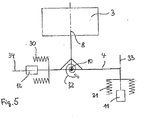
- the rotary body 3 is rotatably mounted with its axis of rotation 8 about the horizontal pivot axis 10; the axis of rotation 8 and the receiving plate 4 can be illustrated by an angle lever with mutually perpendicular lever arms.
- the dynamometer system has a horizontal stiffness indicated by the spring symbol 30, a vertical stiffness indicated by the spring symbol 31, and a rotational rigidity arranged by the rotary spring symbol 32.
- the dash-dotted line 33 shows the active plane of the vibration pickup 11 for the vertical direction, the dotted line 34, the active plane of the vibration pickup 12 for the horizontal direction.
- the horizontal vibration sensor 12 measures the vibration path in the horizontal direction due to the static imbalance.
- the pivot axis 10 remains in the working plane 34 of the horizontal vibration sensor 12, i. in the median plane of the plate-shaped dynamometer.
- the horizontal vibration sensor 12 measures the vibration path in the horizontal direction due to the static unbalance, while the vertical vibration sensor by the pivotal movement of the bell crank assembly. 8 4 measures vibration displacement resulting from the moment unbalance in the vertical direction.
- the pivot axis 10 remains in the active plane 34 of the horizontal vibration 12th
- the pivot axis 10 of this system is no longer in the working plane of the horizontal vibration sensor 12, but outside, resulting in the measurement of e.g. leads to large vibration paths.
Landscapes
- Physics & Mathematics (AREA)
- General Physics & Mathematics (AREA)
- Testing Of Balance (AREA)
- Measurement Of Mechanical Vibrations Or Ultrasonic Waves (AREA)
Claims (11)
- Système de mesure de déséquilibre permettant de déterminer le déséquilibre d'un corps rotatif (3), comprenant un élément dynamomètre (1) en forme de plaque, agencé perpendiculairement à l'axe de rotation (8) dudit corps rotatif, ledit élément dynamomètre comportant un logement (2) maintenant le corps rotatif (3) de manière à ce qu'il puisse tourner autour de l'axe de rotation (8) et pouvant être entraîné d'une manière habituelle par un moteur, ledit élément comportant une plaque réceptrice intérieure (4) reliée à une partie cadre extérieure (5) par l'intermédiaire d'éléments de liaison, ainsi qu'au moins deux capteurs d'oscillation (11, 12) agencés entre la plaque réceptrice (4) et la partie cadre (5), lesquels détectent des oscillations de la plaque réceptrice (4) par rapport à la partie cadre (5) induites par un déséquilibre, un premier des capteurs d'oscillation (11, 12) étant agencé dans le plan de la plaque et détectant des oscillations dans le plan de la plaque, des paires d'éléments de liaison (6, 7, 7') étant agencées de part et d'autre de la plaque réceptrice (4) et étant conçues pour supporter des forces de la plaque réceptrice (4) non induites par un déséquilibre et pour supporter de manière oscillante la plaque réceptrice (4), et une première paire d'éléments de liaison (6) s'étendant dans un plan contenant l'axe de rotation (8) et dans le plan de la plaque, caractérisé en ce que la première paire d'éléments de liaison (6) forme un axe de pivotement (10) pour un mouvement rotatif de la plaque réceptrice (4) agencé perpendiculairement à l'axe de rotation (8) et comprend, pour supporter les forces non induites par un déséquilibre, un profilé rigide en flexion par rapport aux flexions sortant du plan de la plaque et souple en flexion en direction du plan de la plaque, et en ce que des deuxièmes paires d'éléments de liaison (7, 7'), qui s'étendent dans le plan de la plaque à équidistance de part et d'autre de la première paire d'élément de liaison (6) et qui s'étendent en direction de l'extension de la première paire d'éléments de liaison (6) et qui comprennent un profilé souple en flexion par rapport aux flexions sortant du plan de la plaque et en direction du plan de la plaque, et en ce qu'un deuxième des capteurs d'oscillation (11, 12) détecte sensiblement perpendiculairement au plan de la plaque les oscillations de la plaque réceptrice (4) par rapport à la partie cadre (5) induites par un déséquilibre.
- Dispositif selon la revendication 1, caractérisé en ce que le profilé rigide en flexion de la première paire d'éléments de liaison (6) formant l'axe de pivotement (10) est un profilé rectangulaire dont le côté plus long du rectangle s'étend perpendiculairement au plan de la plaque.
- Dispositif selon la revendication 1, caractérisé en ce que les deuxièmes paires d'éléments de liaison (7, 7') s'étendant parallèlement présentent un profilé souple en flexion carré, polygonal ou circulaire.
- Dispositif selon l'une ou plusieurs des revendications précédentes, caractérisé en ce que la plaque réceptrice (4) est de forme rectangulaire et les premières paires d'éléments de liaison (6) sont agencées au centre et les deuxièmes paires d'éléments de liaison (7, 7') sont agencées aux extrémités du côté plus long du rectangle.
- Dispositif selon l'une ou plusieurs des revendications précédentes, caractérisé en ce que les deuxièmes paires d'éléments de liaison (7, 7') s'étendant parallèlement présentent des évidements (20) permettant d'améliorer leur flexibilité perpendiculairement au plan de la plaque.
- Dispositif selon l'une ou plusieurs des revendications précédentes, caractérisé en ce qu'une ou plusieurs des premières ou deuxièmes paires d'éléments de liaison (6, 7, 7') présentent des évidements (21) permettant d'améliorer la flexibilité dans le plan de la plaque.
- Dispositif selon l'une ou plusieurs des revendications précédentes, caractérisé en ce qu'un capteur d'oscillations (11) détectant le mouvement pivotant (10) est en appui à l'extrémité d'un prolongement de la plaque réceptrice (4) dans une avancée de la partie cadre (5).
- Dispositif selon l'une ou plusieurs des revendications précédentes, caractérisé en ce qu'au moins un capteur d'oscillations (11, 12) peut être fixé mobile parallèlement à son axe.
- Dispositif selon l'une ou plusieurs des revendications précédentes, caractérisé en ce que les capteurs d'oscillations détectant le mouvement de pivotement, réalisés sous la forme d'éléments piézoélectriques, sont disposés de manière équidistante de part et d'autre de l'axe de pivotement (10).
- Dispositif selon l'une ou plusieurs des revendications précédentes, caractérisé en ce que des éléments d'accouplement (15, 16, 16') élastiques, de préférence élastiques en flexion, sont prévus entre la plaque réceptrice (4) et les capteurs d'oscillation (11, 12) pour le couplage des capteurs d'oscillation (11, 12).
- Dispositif selon l'une ou plusieurs des revendications précédentes, caractérisé en ce que l'axe de rotation (8) du corps rotatif (3) s'étend dans la direction verticale.
Applications Claiming Priority (2)
| Application Number | Priority Date | Filing Date | Title |
|---|---|---|---|
| DE19937495 | 1999-08-07 | ||
| DE19937495A DE19937495A1 (de) | 1999-08-07 | 1999-08-07 | Einrichtung und Verfahren zur Ermittlung der Unwucht |
Publications (3)
| Publication Number | Publication Date |
|---|---|
| EP1076231A2 EP1076231A2 (fr) | 2001-02-14 |
| EP1076231A3 EP1076231A3 (fr) | 2003-01-15 |
| EP1076231B1 true EP1076231B1 (fr) | 2016-08-17 |
Family
ID=7917697
Family Applications (1)
| Application Number | Title | Priority Date | Filing Date |
|---|---|---|---|
| EP00114139.9A Expired - Lifetime EP1076231B1 (fr) | 1999-08-07 | 2000-07-10 | Dispositif et méthode pour déterminer le deséquilibrage |
Country Status (4)
| Country | Link |
|---|---|
| US (1) | US6779400B1 (fr) |
| EP (1) | EP1076231B1 (fr) |
| JP (1) | JP3990098B2 (fr) |
| DE (1) | DE19937495A1 (fr) |
Families Citing this family (15)
| Publication number | Priority date | Publication date | Assignee | Title |
|---|---|---|---|---|
| DE102004056367B4 (de) * | 2004-11-22 | 2015-07-02 | Schenck Rotec Gmbh | Lagervorrichtung für eine Vorrichtung zur Ermittlung der Unwucht und der Ungleichförmigkeit eines Rotationskörpers |
| EP1904975A4 (fr) * | 2005-07-12 | 2014-05-14 | Technion Res & Dev Foundation | Systeme et procede de detection active d'asymetrie dans des structures rotatives |
| ITMI20061000A1 (it) * | 2006-05-22 | 2007-11-23 | Milano Politecnico | Giunto elastico a cerniera sferica traslante e sensore di forze e momenti perfezionato con tale giunto |
| US7775107B2 (en) * | 2007-10-03 | 2010-08-17 | Hamilton Sundstrand Corporation | Measuring rotor imbalance via blade clearance sensors |
| ITMI20130343A1 (it) * | 2013-03-07 | 2014-09-08 | Carlo Buzzi | Dispositivo per l'equilibratura di ruote. |
| CN103604563B (zh) * | 2013-12-01 | 2016-02-17 | 北京航空航天大学 | 一种基于电流试重的磁悬浮转子不平衡量在线辨识方法 |
| CN104764551B (zh) * | 2015-04-14 | 2017-08-04 | 南京理工大学 | 一种动不平衡冲量测试装置 |
| US9829407B2 (en) | 2015-07-24 | 2017-11-28 | Snap-On Equipment Srl A Unico Socio | Measuring unit and measuring assembly for measuring unbalance forces |
| EP3121577B1 (fr) * | 2015-07-24 | 2020-02-12 | Snap-on Equipment Srl a unico socio | Unité et ensemble de mesure pour mesurer des forces de déséquilibre |
| EP3121578B1 (fr) * | 2015-07-24 | 2023-05-10 | Snap-on Equipment Srl a unico socio | Système de communication pour une machine de service de pneu et unité de mesure destinée à être utilisée avec un tel système de communication |
| US9816899B2 (en) | 2015-07-24 | 2017-11-14 | Snap-On Equipment Srl A Unico Socio | Communication system for a tyre service machine and measuring unit for being used with such communication system |
| EP3545277A4 (fr) * | 2016-11-24 | 2020-08-05 | The University Of Queensland | Dispositif de détection de force |
| CN111157107B (zh) * | 2020-02-05 | 2021-11-30 | 山东联合电力产业发展有限公司 | 一种高稳定型发电机摆度测量装置 |
| CN112834091A (zh) * | 2020-12-31 | 2021-05-25 | 苏州大学 | 微装配用微力传感器及压电陶瓷驱动微夹持器 |
| CN120395533B (zh) * | 2025-07-01 | 2025-10-17 | 山东辰榜数控装备有限公司 | 一种机床加工零件测试机构 |
Citations (2)
| Publication number | Priority date | Publication date | Assignee | Title |
|---|---|---|---|---|
| GB1388047A (en) * | 1971-03-22 | 1975-03-19 | Dunlop Ltd | Uniformity testing machines |
| US4930348A (en) * | 1988-11-25 | 1990-06-05 | Balance Engineering Corporation | Vertical balancing machine with cartridge assembly |
Family Cites Families (11)
| Publication number | Priority date | Publication date | Assignee | Title |
|---|---|---|---|---|
| DE1237807B (de) * | 1961-10-13 | 1967-03-30 | Schenck Gmbh Carl | Auswuchtmaschine |
| DE1937865B2 (de) * | 1969-07-25 | 1974-05-16 | Carl Schenck Maschinenfabrik Gmbh, 6100 Darmstadt | Lagerständer für Auswuchtmaschinen |
| DE2114770B1 (de) * | 1971-03-26 | 1972-06-29 | Gebr Hofmann Kg Maschinenfabrik | Vorrichtung zum Auswuchten von Unwuchtkörpern |
| DE2608891C2 (de) * | 1976-03-04 | 1979-11-29 | Carl Schenck Ag, 6100 Darmstadt | Federanordnung zur schwingenden Abstützung der Umlaufkörperlagerung in einer Auswuchtmaschine |
| DE2847295C2 (de) * | 1978-10-31 | 1983-02-03 | Schenck Auto-Service-Geräte GmbH, 6100 Darmstadt | Vorrichtung zur Bestimmung der Unwucht eines von einer Aufnahme einer Auswuchtmaschine mit Lagerständer gehaltenen Rotationskörpers |
| DE2942379A1 (de) * | 1979-10-19 | 1981-04-23 | Gebr. Hofmann Gmbh & Co Kg Maschinenfabrik, 6100 Darmstadt | Auswuchtmaschine zum auswuchten von rotationskoerpern in mindestens zwei ebenen |
| DE3330974C2 (de) * | 1983-08-27 | 1986-07-24 | Hofmann Werkstatt-Technik GmbH, 6102 Pfungstadt | Vorrichtung zur Bestimmung der statischen Unwucht eines Prüfkörpers |
| US4640138A (en) * | 1985-03-06 | 1987-02-03 | Mts Systems Corporation | Multiple axis load sensitive transducer |
| EP0381712B1 (fr) * | 1988-07-18 | 1992-03-04 | Wirth Gallo Messtechnik Ag | Appareil de mesure et de forces a reduction d'elasticite |
| US5677487A (en) * | 1995-10-13 | 1997-10-14 | A/S Bruel & Kjaer | Method and apparatus for measuring acceleration or mechanical forces |
| US5784929A (en) * | 1996-09-10 | 1998-07-28 | Illinois Tool Works Inc. | Dynamometer torsional damping apparatus |
-
1999
- 1999-08-07 DE DE19937495A patent/DE19937495A1/de not_active Withdrawn
-
2000
- 2000-07-10 EP EP00114139.9A patent/EP1076231B1/fr not_active Expired - Lifetime
- 2000-08-07 US US09/633,681 patent/US6779400B1/en not_active Expired - Fee Related
- 2000-08-07 JP JP2000239018A patent/JP3990098B2/ja not_active Expired - Fee Related
Patent Citations (2)
| Publication number | Priority date | Publication date | Assignee | Title |
|---|---|---|---|---|
| GB1388047A (en) * | 1971-03-22 | 1975-03-19 | Dunlop Ltd | Uniformity testing machines |
| US4930348A (en) * | 1988-11-25 | 1990-06-05 | Balance Engineering Corporation | Vertical balancing machine with cartridge assembly |
Also Published As
| Publication number | Publication date |
|---|---|
| DE19937495A1 (de) | 2001-02-08 |
| JP3990098B2 (ja) | 2007-10-10 |
| US6779400B1 (en) | 2004-08-24 |
| EP1076231A2 (fr) | 2001-02-14 |
| JP2001074584A (ja) | 2001-03-23 |
| EP1076231A3 (fr) | 2003-01-15 |
Similar Documents
| Publication | Publication Date | Title |
|---|---|---|
| EP1076231B1 (fr) | Dispositif et méthode pour déterminer le deséquilibrage | |
| EP1108204B1 (fr) | Dispositifs de mesure d'un defaut d'equilibrage d'un rotor comportant au moins une zone d'appui virtuelle | |
| EP2944966B1 (fr) | Capteur de vibrations | |
| DE102008043796A1 (de) | Drehratensensor | |
| DE2732738C2 (de) | Vorrichtung zum Auswuchten von Unwuchtkörpern, insbesondere von Kraftfahrzeug-Rädern | |
| EP2470873B1 (fr) | Banc d'essai à amortisseur d'oscillations | |
| DE4342667C2 (de) | Vorrichtung zur schwingungsfähigen Abstützung einer Rotorlagerung für einen auszuwuchtenden Rotor in einer Auswuchtmaschine | |
| DE2215002A1 (de) | Auswuchtmaschine | |
| EP0010785B1 (fr) | Procédé et dispositif de détection de déséquilibre d'un corps en rotation | |
| EP1346192A1 (fr) | Capteur inertiel micromecanique | |
| EP4279892A1 (fr) | Dispositif de mesure permettant de mesurer des pneus en ce qui concerne le balourd et l'uniformité | |
| EP0343265B1 (fr) | Méthode de fabrication d'un support pour une équilibreuse | |
| DE202008018289U1 (de) | Auswuchtmaschine für sich drehende Körper, insbesondere für Kraftfahrzeugräder | |
| DE2254272A1 (de) | Vorrichtung zum pruefen von fahrzeugfederungen | |
| DE4428758C1 (de) | Vorrichtung zur Ermittlung des Übertragungsverhaltens eines elastischen Lagers | |
| DE102011000054B4 (de) | Torsionssensor | |
| DE102004056367B4 (de) | Lagervorrichtung für eine Vorrichtung zur Ermittlung der Unwucht und der Ungleichförmigkeit eines Rotationskörpers | |
| DE19844975C2 (de) | Vorrichtung zur Messung von Kräften, welche durch eine Unwucht eines Rotors erzeugt werden | |
| DE1698164B1 (de) | Auswuchtmaschine mit mechanischem rahmen | |
| DE2732574A1 (de) | Drehgekoppelte winkelgeschwindigkeitsempfindliche inertial-sensoren mit montagestruktur und verfahren zu deren herstellung und anbringung | |
| DE10001356A1 (de) | Vorrichtung zur Messung von Kräften, welche durch eine Unwucht eines Rotors erzeugt werden | |
| DE2608891B1 (de) | Federanordnung zur schwingenden abstuetzung der umlaufkoerperlagerung in einer auswuchtmaschine | |
| EP2373968A1 (fr) | Dispositif d'équilibrage avec palier supplémentaire | |
| DE102009022651B3 (de) | Vorrichtung zum Messen der Unwucht eines Rotors | |
| DE102016015057B3 (de) | Messsystem |
Legal Events
| Date | Code | Title | Description |
|---|---|---|---|
| PUAI | Public reference made under article 153(3) epc to a published international application that has entered the european phase |
Free format text: ORIGINAL CODE: 0009012 |
|
| AK | Designated contracting states |
Kind code of ref document: A2 Designated state(s): AT BE CH CY DE DK ES FI FR GB GR IE IT LI LU MC NL PT SE |
|
| AX | Request for extension of the european patent |
Free format text: AL;LT;LV;MK;RO;SI |
|
| PUAL | Search report despatched |
Free format text: ORIGINAL CODE: 0009013 |
|
| AK | Designated contracting states |
Kind code of ref document: A3 Designated state(s): AT BE CH CY DE DK ES FI FR GB GR IE IT LI LU MC NL PT SE |
|
| AX | Request for extension of the european patent |
Free format text: AL;LT;LV;MK;RO;SI |
|
| 17P | Request for examination filed |
Effective date: 20030412 |
|
| AKX | Designation fees paid |
Designated state(s): AT BE CH CY DE DK ES FI FR GB GR IE IT LI LU MC NL PT SE |
|
| 17Q | First examination report despatched |
Effective date: 20080312 |
|
| GRAP | Despatch of communication of intention to grant a patent |
Free format text: ORIGINAL CODE: EPIDOSNIGR1 |
|
| INTG | Intention to grant announced |
Effective date: 20160316 |
|
| GRAS | Grant fee paid |
Free format text: ORIGINAL CODE: EPIDOSNIGR3 |
|
| GRAA | (expected) grant |
Free format text: ORIGINAL CODE: 0009210 |
|
| AK | Designated contracting states |
Kind code of ref document: B1 Designated state(s): AT BE CH CY DE DK ES FI FR GB GR IE IT LI LU MC NL PT SE |
|
| REG | Reference to a national code |
Ref country code: GB Ref legal event code: FG4D Free format text: NOT ENGLISH |
|
| REG | Reference to a national code |
Ref country code: CH Ref legal event code: EP |
|
| REG | Reference to a national code |
Ref country code: IE Ref legal event code: FG4D Free format text: LANGUAGE OF EP DOCUMENT: GERMAN |
|
| REG | Reference to a national code |
Ref country code: AT Ref legal event code: REF Ref document number: 821553 Country of ref document: AT Kind code of ref document: T Effective date: 20160915 |
|
| REG | Reference to a national code |
Ref country code: DE Ref legal event code: R096 Ref document number: 50016456 Country of ref document: DE |
|
| REG | Reference to a national code |
Ref country code: NL Ref legal event code: MP Effective date: 20160817 |
|
| PG25 | Lapsed in a contracting state [announced via postgrant information from national office to epo] |
Ref country code: IT Free format text: LAPSE BECAUSE OF FAILURE TO SUBMIT A TRANSLATION OF THE DESCRIPTION OR TO PAY THE FEE WITHIN THE PRESCRIBED TIME-LIMIT Effective date: 20160817 Ref country code: FI Free format text: LAPSE BECAUSE OF FAILURE TO SUBMIT A TRANSLATION OF THE DESCRIPTION OR TO PAY THE FEE WITHIN THE PRESCRIBED TIME-LIMIT Effective date: 20160817 Ref country code: NL Free format text: LAPSE BECAUSE OF FAILURE TO SUBMIT A TRANSLATION OF THE DESCRIPTION OR TO PAY THE FEE WITHIN THE PRESCRIBED TIME-LIMIT Effective date: 20160817 |
|
| PG25 | Lapsed in a contracting state [announced via postgrant information from national office to epo] |
Ref country code: GR Free format text: LAPSE BECAUSE OF FAILURE TO SUBMIT A TRANSLATION OF THE DESCRIPTION OR TO PAY THE FEE WITHIN THE PRESCRIBED TIME-LIMIT Effective date: 20161118 Ref country code: PT Free format text: LAPSE BECAUSE OF FAILURE TO SUBMIT A TRANSLATION OF THE DESCRIPTION OR TO PAY THE FEE WITHIN THE PRESCRIBED TIME-LIMIT Effective date: 20161219 Ref country code: ES Free format text: LAPSE BECAUSE OF FAILURE TO SUBMIT A TRANSLATION OF THE DESCRIPTION OR TO PAY THE FEE WITHIN THE PRESCRIBED TIME-LIMIT Effective date: 20160817 Ref country code: SE Free format text: LAPSE BECAUSE OF FAILURE TO SUBMIT A TRANSLATION OF THE DESCRIPTION OR TO PAY THE FEE WITHIN THE PRESCRIBED TIME-LIMIT Effective date: 20160817 |
|
| REG | Reference to a national code |
Ref country code: DE Ref legal event code: R097 Ref document number: 50016456 Country of ref document: DE |
|
| PG25 | Lapsed in a contracting state [announced via postgrant information from national office to epo] |
Ref country code: DK Free format text: LAPSE BECAUSE OF FAILURE TO SUBMIT A TRANSLATION OF THE DESCRIPTION OR TO PAY THE FEE WITHIN THE PRESCRIBED TIME-LIMIT Effective date: 20160817 |
|
| PLBE | No opposition filed within time limit |
Free format text: ORIGINAL CODE: 0009261 |
|
| STAA | Information on the status of an ep patent application or granted ep patent |
Free format text: STATUS: NO OPPOSITION FILED WITHIN TIME LIMIT |
|
| 26N | No opposition filed |
Effective date: 20170518 |
|
| REG | Reference to a national code |
Ref country code: CH Ref legal event code: PL |
|
| GBPC | Gb: european patent ceased through non-payment of renewal fee |
Effective date: 20170710 |
|
| REG | Reference to a national code |
Ref country code: IE Ref legal event code: MM4A |
|
| REG | Reference to a national code |
Ref country code: FR Ref legal event code: ST Effective date: 20180330 |
|
| PG25 | Lapsed in a contracting state [announced via postgrant information from national office to epo] |
Ref country code: IE Free format text: LAPSE BECAUSE OF NON-PAYMENT OF DUE FEES Effective date: 20170710 Ref country code: CH Free format text: LAPSE BECAUSE OF NON-PAYMENT OF DUE FEES Effective date: 20170731 Ref country code: LI Free format text: LAPSE BECAUSE OF NON-PAYMENT OF DUE FEES Effective date: 20170731 Ref country code: GB Free format text: LAPSE BECAUSE OF NON-PAYMENT OF DUE FEES Effective date: 20170710 |
|
| PG25 | Lapsed in a contracting state [announced via postgrant information from national office to epo] |
Ref country code: FR Free format text: LAPSE BECAUSE OF NON-PAYMENT OF DUE FEES Effective date: 20170731 |
|
| REG | Reference to a national code |
Ref country code: BE Ref legal event code: MM Effective date: 20170731 |
|
| PG25 | Lapsed in a contracting state [announced via postgrant information from national office to epo] |
Ref country code: LU Free format text: LAPSE BECAUSE OF NON-PAYMENT OF DUE FEES Effective date: 20170710 |
|
| PG25 | Lapsed in a contracting state [announced via postgrant information from national office to epo] |
Ref country code: BE Free format text: LAPSE BECAUSE OF NON-PAYMENT OF DUE FEES Effective date: 20170731 |
|
| REG | Reference to a national code |
Ref country code: AT Ref legal event code: MM01 Ref document number: 821553 Country of ref document: AT Kind code of ref document: T Effective date: 20170710 |
|
| PGFP | Annual fee paid to national office [announced via postgrant information from national office to epo] |
Ref country code: DE Payment date: 20180910 Year of fee payment: 19 |
|
| PG25 | Lapsed in a contracting state [announced via postgrant information from national office to epo] |
Ref country code: AT Free format text: LAPSE BECAUSE OF NON-PAYMENT OF DUE FEES Effective date: 20170710 |
|
| PG25 | Lapsed in a contracting state [announced via postgrant information from national office to epo] |
Ref country code: MC Free format text: LAPSE BECAUSE OF FAILURE TO SUBMIT A TRANSLATION OF THE DESCRIPTION OR TO PAY THE FEE WITHIN THE PRESCRIBED TIME-LIMIT Effective date: 20160817 |
|
| PG25 | Lapsed in a contracting state [announced via postgrant information from national office to epo] |
Ref country code: CY Free format text: LAPSE BECAUSE OF NON-PAYMENT OF DUE FEES Effective date: 20160817 |
|
| REG | Reference to a national code |
Ref country code: DE Ref legal event code: R119 Ref document number: 50016456 Country of ref document: DE |
|
| PG25 | Lapsed in a contracting state [announced via postgrant information from national office to epo] |
Ref country code: DE Free format text: LAPSE BECAUSE OF NON-PAYMENT OF DUE FEES Effective date: 20200201 |