EP1076246A1 - Piece optique et procede de fabrication correspondant - Google Patents
Piece optique et procede de fabrication correspondant Download PDFInfo
- Publication number
- EP1076246A1 EP1076246A1 EP99909305A EP99909305A EP1076246A1 EP 1076246 A1 EP1076246 A1 EP 1076246A1 EP 99909305 A EP99909305 A EP 99909305A EP 99909305 A EP99909305 A EP 99909305A EP 1076246 A1 EP1076246 A1 EP 1076246A1
- Authority
- EP
- European Patent Office
- Prior art keywords
- core
- optical
- optical component
- optical fibers
- clad
- Prior art date
- Legal status (The legal status is an assumption and is not a legal conclusion. Google has not performed a legal analysis and makes no representation as to the accuracy of the status listed.)
- Granted
Links
Images


Classifications
-
- G—PHYSICS
- G02—OPTICS
- G02B—OPTICAL ELEMENTS, SYSTEMS OR APPARATUS
- G02B6/00—Light guides; Structural details of arrangements comprising light guides and other optical elements, e.g. couplings
- G02B6/02—Optical fibres with cladding with or without a coating
- G02B6/02042—Multicore optical fibres
-
- G—PHYSICS
- G02—OPTICS
- G02B—OPTICAL ELEMENTS, SYSTEMS OR APPARATUS
- G02B6/00—Light guides; Structural details of arrangements comprising light guides and other optical elements, e.g. couplings
- G02B6/04—Light guides; Structural details of arrangements comprising light guides and other optical elements, e.g. couplings formed by bundles of fibres
- G02B6/06—Light guides; Structural details of arrangements comprising light guides and other optical elements, e.g. couplings formed by bundles of fibres the relative position of the fibres being the same at both ends, e.g. for transporting images
- G02B6/08—Light guides; Structural details of arrangements comprising light guides and other optical elements, e.g. couplings formed by bundles of fibres the relative position of the fibres being the same at both ends, e.g. for transporting images with fibre bundle in form of plate
Definitions
- the present invention relates to an optical component comprising a plurality of optical fibers arranged, and a production method thereof.
- an optical component formed by arranging a plurality of optical fibers is widely known.
- the optical component comprises an incident surface and an output surface with the core and the clad of each optical fiber exposed so as to allow transmission of the optical image incident on the incident surface to the output surface.
- the optical component since the optical component has various advantages, such as a high transmission efficiency, and capability of achieving a small size of an optical system compared with a lens, it is utilized in various fields represented by a fingerprint detecting device.
- Production of the optical component is executed, in general, by arranging and tying up a plurality of optical fibers having a round or square cross-section in a bundle for integral shaping. Therefore, according to the pressure in the integral shaping, the cross-section of the core of the optical fibers comprising the optical component becomes a polygon having subtenses parallel with each other, such as a square, and a hexagon so that the below-mentioned problem is generated.
- a light incident on the incident surface with a specific incident angle repeats reflection on the opposite surfaces parallel with each other so as to be outputted from the output surface with a specific output angle.
- a pattern having an intensity only in the specific output angle is formed in the output image outputted from the output surface so that the pattern becomes a noise so as to deteriorate the resolution of the optical component.
- an object of the present invention is to provide an optical component having a high resolution by preventing generation of the pattern noise and production method of the optical component.
- an optical component according to the present invention comprises a plurality of arranged optical fibers including a core and a clad formed around the core, characterized in that the core of each optical fiber having a substantially square cross-sectional shape, is divided into a plurality of areas via a partition part made from a material with a refractive index smaller than that of the core, and at least one of the optical fibers arranged adjacent with each other has the dividing direction of the divided core different from that of the other optical fibers.
- each optical fiber Since the core of each optical fiber is divided into a plurality of areas via a partition part made from a material having a refractive index smaller than that of the core, a light incident on the core of each optical fiber with a specific incident angle proceeds in the core while repeating reflection not only by the surrounding clad but also by the partition part. Moreover, since at least one of the optical fibers arranged adjacent with each other has the dividing direction of the divided core different from that of the other optical fibers, even though the cross-sectional shape of the core is a substantial square having subtenses parallel with each other, formation of a pattern having an intensity only at a specific incident angle by repeating reflection of a light proceeding in the cores in all the optical fibers comprising the optical component only in a specific direction can be prevented. As a result, a pattern noise can be prevented so that an output image with a high resolution can be obtained.
- a production method of an optical component comprises an arrangement step of arranging a plurality of optical fibers including a core and a clad formed around the core, and a shaping step of integrally shaping the plurality of the optical fibers arranged in the arrangement step by a heating and pressuring treatment, characterized in that the core of each optical fiber is divided into a plurality of areas via a partition part made from a material with a refractive index smaller than that of the core, at least one of the optical fibers arranged adjacent with each other is arranged with the dividing direction of the divided core different from that of the other optical fibers in the arrangement step, and the viscosity of the core under the temperature of the heating and pressuring treatment is smaller than the viscosity of the clad in the shaping step.
- the optical component can be produced easily.
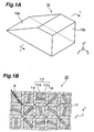
- FIG. 1A is a perspective view of the optical component according to this embodiment
- FIG. 1B is an enlarged cross-sectional view taken along the line I-I (straight line parallel with the x-axis) in FIG. 1A.
- the optical component 10 is formed with a plurality of optical fibers having a square cross-sectional shape of the core, arranged parallel with each other. Each optical fiber has the fiber axis disposed parallel with the y-axis in FIG. 1A.
- the optical component 10 has an incident surface 10a obliquely cut with respect to the fiber axis, and an output surface 10b perpendicularly cut with respect to the fiber axis so that an input pattern incident on the incident surface 10a can be reduced and outputted from the output surface 10b.
- the cross-section of the optical component 10 has a structure with the optical fibers having the core 12 with a square cross-section arranged.
- the core 12 of each optical fiber is divided equally into two areas 12a and 12b via a flat plate-like clad part 14 (partition part) lying on the central axis of the core 12.
- at least one of the optical fibers arranged adjacent with each other has the dividing direction (t direction in FIG. 1B) of the divided core 12 different from that of the other optical fibers. More specifically speaking, the dividing directions (t direction in FIG. 1B) of the divided cores 12 are arranged irregularly per each optical fiber.
- the periphery of each core 12 is covered with a clad 16.
- the clad 16 of each optical fiber is integrated by a heating and pressuring treatment so as to fill the gap among the adjacent optical fibers.
- the core 12 of each optical fiber is made from, for example, a Ba-La based glass having a 1.82 refractive index
- the clad part 14 and the clad 16 are made from, for example, a borosilicate glass having a 1.495 refractive index. Therefore, the refractive index of the clad part 14 is smaller than the refractive index of the core 12.
- one side of the core 12 is about 10 ⁇ m
- the clad part 14 and the clad 16 has about 1 ⁇ m thickness, which is 1/3 or more with respect to the wavelength (550 nm) ordinarily used in the optical component 10.
- a light absorbing member 17 elongating in the axial direction of each optical fiber is inserted in the part of the clad 16.
- a stray light leaked in the clad 16 or a light entered into the optical component 10 from the side surface (surface other than the incident surface and the output surface) can be eliminated effectively so that the resolution of an output pattern can be improved.
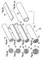
- FIGS. 2A to 2F are production step diagrams for an optical fiber comprising the optical component 10
- FIGS. 2G to 2J are cross-sectional view of a base material, or the like, produced in each step.
- a core base material 18 having a columnar shape is produced (FIG. 2A, FIG. 2G).
- the core base material 18 is made from, for example, a Ba-La based glass having a 1.82 refractive index, with the side surface thereof polished by a ceria polish method, or the like.
- the core base material 18 produced in the above-mentioned step is cut vertically (perpendicular direction with respect to the bottom surface of the columnar shape) by a diamond cutter, or the like so as to be divided into two core base materials 20 and 22 having a semi-columnar shape (FIG. 2B, FIG. 2H).
- the cut surface is polished by a ceria polish method, or the like.
- a plate-like clad base material 24 as shown in FIG. 2C is interposed between the two core base materials 20 and 22 (FIG. 2D, FIG. 2I).
- the clad base material 24 is made from, for example, a borosilicate glass having a 1.495 refractive index.
- the product of the above-mentioned step with the plate-like clad base material 24 interposed between the two core base materials 20 and 22 is put in a clad base material 26 having a pipe shape as shown in FIG. 2E so as to produce a base material 28 for the optical fiber production (FIG. 2F, FIG. 2J).
- the clad base material 26 is made from, for example, a borosilicate glass having a 1.495 refractive index.
- One bottom part 26a of the clad base material 26 is sealed by a melting method with a burner, or the like.
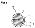
- the optical fiber 30 has a structure with the core 12 having a round cross-section equally divided into the two areas 12a and 12b having a semi-circular cross-section via the flat plate-like clad part 14 lying on the central axis of the core 12, and the periphery thereof covered with the clad 16.
- a plurality of the optical fibers 30 produced by the above-mentioned step are arranged in the quadrilateral arrangement parallel with each other with the bar-like light absorbing members 17 optionally inserted such that the dividing direction of the cores 12 can be irregular par each optical fiber so as to be shaped integrally by a heating and pressuring treatment for producing the optical component 10.
- the thickness of the clad part 14 is about 1 ⁇ m, and the thickness of the clad 16 is about 0.5 ⁇ m.
- the shape of the core 12 is deformed at the time of the heating and pressuring treatment so that the core 12 obtains a square cross-sectional shape as shown in FIG. 4B.
- An optical component according to the conventional technique is produced by, in general, arranging and tying up a plurality of optical fibers having a round or square cross-section parallel with each other in a bundle for integral shaping. Moreover, in order to improve the resolution of the optical component, an optical component can be produced also by arranging parallel and tying up the tied up optical fiber group further drawn (multi-fiber) for integral shaping, or by integral shaping of those after repetition of the drawing step and the tying up step (multi-multi-fiber).
- FIGS. 17A to 17C show Changes of the cross-sectional shape of the core of each optical fiber in production of the optical component according to the above-mentioned production method.
- FIGS. 17A to 17C show the change of the cross-sectional shape of the cores 2 in the case the optical component 6 is formed by arranging the optical fibers 4 with the cores 2 having a round cross-section arranged in the quadrilateral arrangement.
- the cross-section of the core 2 of each optical fiber 4 is deformed substantially to a square according to the heating and pressuring treatment at the time of integral shaping after typing up the optical fibers 4.
- the degree of the deformation depends on the hardness of the cores 2 and the clads 8 of the optical fibers 4 under the temperature of the heating and pressuring treatment.
- the cores 2 are extremely harder than the clads 8
- the cross-section of the cores 2 can be maintained in a round shape, but in order to avoid the contact of the adjacent cores 2 with each other, it is difficult to have the cores 2 extremely harder than the clads 8 in the practical use.
- FIGS. 18A to 18C show the change of the cross-sectional shape of the cores 2 in the case the optical component 6 is formed by arranging the optical fibers 4 with the cores 2 having a round cross-section arranged in the hexagonal arrangement.
- the cross-section of the core 2 of each optical fiber 4 is deformed substantially to a hexagon according to the heating, and pressuring treatment at the time of integral shaping after typing up the optical fibers 4.
- FIGS. 19A to 19C show the change of the cross-sectional shape of the cores 2 in the case the optical component 6 is formed by arranging the optical fibers 4 with the cores 2 having a square cross-section arranged in the quadrilateral arrangement.
- the cross-section of the core 2 is kept square after he heating and pressuring treatment at the time of integral shaping after typing up the optical fibers 4.
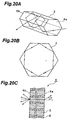
- the optical components 6 produced as mentioned above have a pentagonal cross-section of the core 2 of each optical fiber 4 having subtenses parallel with each other, such as a square, and a hexagon, the below-mentioned problem is generated. That is, the progress of a light incident on the incident surface of the optical component 6 in the core 2 can either be the spiral progress as shown in FIGS. 20A to 20C or the band-like progress as shown in FIGS. 21A to 21C.
- the white round mark and the black round mark in FIGS. 20A to 20C and FIGS. 21A to 21C show the light incident position.
- FIG. 20A shows the state of the progress of a light incident on the incident surface 6a(incident surface of the core 2) of the optical component 6 in the core 2
- FIG. 20B is a projection diagram of the track of the progress of the light on a plane parallel with the incident surface 6a.
- a light incident on the incident surface 6a of the optical component 6 with a random incident angle (excluding a specific incident angle to be explained with reference to FIGS. 21A to 21C) proceeds spirally in the core 2.
- FIG. 20C in the case a light is incident on the incident surface 6a of the optical component 6 with a constant incident angle ⁇ , depending on the difference of the incident position, it is outputted from the output surface 6b of the optical component 6 with various output angles.
- a pattern having an intensity only at a specific incident angle is formed in an output image outputted form the output surface 6b of the optical component 6 so that the pattern becomes a noise deteriorating the resolution of the optical component 6.
- an optical component produced by integral shaping of multi-fibers has different degrees of the core 2 deformation at the center part and the rim part of the multi-fibers, a pattern noise is generated according to the cross-sectional shapes of the multi-fibers, derived from the difference of the deformation degrees so that the resolution of the optical component 6 is deteriorated remarkably.
- the optical component 10 has the core 12 of each optical fiber comprising the optical component 10 divided equally into a plurality of areas 12a and 12b via a flat plate-like clad part 14 lying on the central axis of the core 12. Therefore, a light incident on the core 12 of each optical fiber with a specific incident angle proceeds in the core while repeating reflection not only by the surrounding clad 16 but also by the clad part 14. Thereby, even though the cross-sectional shape of the core 12 is a square having subtenses parallel with each other, unless the clad part 14 is parallel with the interface between the core 12 and the clad 16, the light incident on the incident surface 10a cannot proceeds band-like in the core 12.
- the dividing directions of the divided cores 12 in the optical component 10 are arranged irregularly per each optical fiber, even in the case the clad part 14 is parallel with the interface between the core 12 and the clad 16 in a part of the optical fibers comprising the optical component 10, the optical fibers having the clad part 14 not parallel with the interface between the core 12 and the clad part 16 exist at the same time so that formation of an output pattern having an intensity only at a specific output angle by repeating reflection of a light proceeding in the cores 12 in the optical fibers comprising the optical component 10 only in a specific direction can be prevented.
- the optical component 10 has the core 12 of each optical fiber comprising the optical component 10 divided equally into a plurality of areas 12a and 12b via the flat plate-like clad part 14 and the dividing directions of the divided cores 12 in the optical component 10 are arranged irregularly per each optical fiber, formation of an output pattern having an intensity only at a specific output angle by repeating reflection of all of the light proceeding in the cores 12 in the optical fibers comprising the optical component 10 only in a specific direction can be prevented. As a result, a pattern noise can be prevented so that an output image with a high resolution can be obtained from the output surface 10b of the optical component 10.
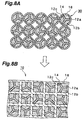
- the integral shaping can be executed with the optical fibers 30 arranged in the hexagonal dense arrangement as shown in FIG. 6A.
- the shape of the cores 12 is deformed at the time of the heating and pressuring treatment so that the cross-section of the optical component 10 becomes as shown in FIG. 6B.
- the core 12 of each optical fiber has a regular hexagonal cross-sectional shape as well as it is divided equally into the two areas 12a and 12b via the flat plate-like clad part 14 lying on the central axis of the core, with the optical fibers arranged such that the dividing directions of the divided cores 12 are irregular per each optical fiber.
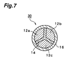
- the integral shaping can be executed also with the optical fibers 30 with the cores 12 equally divided via the clad parts 14 into a plurality of, that is, three, four, or six areas arranged.
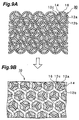
- the integral shaping of the optical fibers 30 with the core 12 equally divided into the three areas 12a to 12c via the clad part 14 shown in FIG. 7 arranged in the quadrilateral dense arrangement as shown in FIG. 8A the optical component 10 with each core 12 having a square cross-sectional shape as shown in FIG.
- the optical component 10 with each core 12 substantially having a hexagonal cross-sectional shape as shown in FIG. 9B as well as divided equally into the three areas 12a to 12c can be provided.
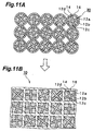
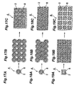
- the optical component 10 with each core 12 having a square cross-sectional shape as shown in FIG. 11B as well as divided equally into the four areas 12a to 12d can be provided, or by the integral shaping in the hexagonal dense arrangement as shown in FIG. 12A, the optical component 10 with each core 12 substantially having a hexagonal cross-sectional shape as shown in FIG. 12B as well as divided equally into the four areas 12a to 12d can be provided.
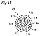
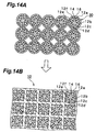
- the optical component 10 with each core 12 having a square cross-sectional shape as shown in FIG. 14B as well as divided equally into the six areas 12a to 12f can be provided, or by the integral shaping in the hexagonal dense arrangement as shown in FIG. 15A, the optical component 10 with each core 12 substantially having a hexagonal cross-sectional shape as shown in FIG. 15B as well as divided equally into the six areas 12a to 12f can be provided.
- the core 12 is divided equally into a plurality of areas via the flat plate-like clad part 14 lying on the central axis of the core 12 in the above-mentioned embodiment, it is not limited to the division by the flat plate lying on the central axis, or the equal division into a plurality of areas. That is, for example, as shown in FIG. 16, the optical component 10 can be formed, using the optical fibers 30 with the cores 12 divided into a T-shape.
- optical components 10 are optical components with a plurality of optical fibers arranged parallel, they can be optical components having a tapered shape with a plurality of optical fibers having a curved part arranged for outputting an optical image incident on the incident surface with enlargement or reduction.
- optical components Since the above-mentioned optical components have various advantages such as a high transmission efficiency, and capability of downsizing of an optical system compared with a lens, they can be utilized in various areas such as a fingerprint detecting device, and a radiation detecting device.
Landscapes
- Physics & Mathematics (AREA)
- General Physics & Mathematics (AREA)
- Optics & Photonics (AREA)
- Optical Fibers, Optical Fiber Cores, And Optical Fiber Bundles (AREA)
- Optical Couplings Of Light Guides (AREA)
Applications Claiming Priority (3)
| Application Number | Priority Date | Filing Date | Title |
|---|---|---|---|
| JP11749198 | 1998-04-27 | ||
| JP11749198 | 1998-04-27 | ||
| PCT/JP1999/001446 WO1999056161A1 (fr) | 1998-04-27 | 1999-03-23 | Piece optique et procede de fabrication correspondant |
Publications (3)
| Publication Number | Publication Date |
|---|---|
| EP1076246A1 true EP1076246A1 (fr) | 2001-02-14 |
| EP1076246A4 EP1076246A4 (fr) | 2002-10-24 |
| EP1076246B1 EP1076246B1 (fr) | 2005-03-16 |
Family
ID=14713049
Family Applications (1)
| Application Number | Title | Priority Date | Filing Date |
|---|---|---|---|
| EP99909305A Expired - Lifetime EP1076246B1 (fr) | 1998-04-27 | 1999-03-23 | Faisceau de fibres optiques pour la transmission d'image et procede de fabrication correspondant |
Country Status (7)
| Country | Link |
|---|---|
| US (1) | US6496644B1 (fr) |
| EP (1) | EP1076246B1 (fr) |
| JP (1) | JP3842552B2 (fr) |
| CN (1) | CN1210585C (fr) |
| AU (1) | AU2855199A (fr) |
| DE (1) | DE69924247T2 (fr) |
| WO (1) | WO1999056161A1 (fr) |
Cited By (2)
| Publication number | Priority date | Publication date | Assignee | Title |
|---|---|---|---|---|
| EP3737980A4 (fr) * | 2018-01-14 | 2021-11-10 | Light Field Lab, Inc. | Systèmes et procédés de localisation d'énergie transversale dans des relais d'énergie à l'aide de structures ordonnées |
| US12061356B2 (en) | 2016-07-15 | 2024-08-13 | Light Field Lab, Inc. | High density energy directing device |
Families Citing this family (3)
| Publication number | Priority date | Publication date | Assignee | Title |
|---|---|---|---|---|
| EP1184339A3 (fr) | 2000-09-01 | 2002-09-04 | A.R.T.-Photonics GmbH | Fibre optique et procédés de fabrication d'une fibre optique |
| US6672773B1 (en) * | 2000-12-29 | 2004-01-06 | Amkor Technology, Inc. | Optical fiber having tapered end and optical connector with reciprocal opening |
| DE10319888A1 (de) | 2003-04-25 | 2004-11-25 | Siemens Ag | Lotmaterial auf SnAgCu-Basis |
Family Cites Families (8)
| Publication number | Priority date | Publication date | Assignee | Title |
|---|---|---|---|---|
| US2825260A (en) * | 1954-11-19 | 1958-03-04 | O'brien Brian | Optical image forming devices |
| US3387959A (en) * | 1962-11-19 | 1968-06-11 | American Optical Corp | Method for forming image-transfer devices embodying light-conducting fibers and light-absorbing filaments |
| DE1249559B (fr) * | 1962-11-19 | |||
| US3323886A (en) * | 1963-05-01 | 1967-06-06 | American Optical Corp | Radiation absorption heating of a bundle of glass fibers |
| JPS5035628Y1 (fr) * | 1967-08-07 | 1975-10-17 | ||
| JPS4859849A (fr) * | 1971-11-25 | 1973-08-22 | ||
| AU475580B2 (en) | 1973-06-18 | 1976-08-26 | United Aircraft Corporation | Battery peaking unit for fuel cell power plants |
| JPH08338916A (ja) * | 1995-06-12 | 1996-12-24 | Hamamatsu Photonics Kk | ファイバー光学プレート |
-
1999
- 1999-03-23 AU AU28551/99A patent/AU2855199A/en not_active Abandoned
- 1999-03-23 WO PCT/JP1999/001446 patent/WO1999056161A1/fr not_active Ceased
- 1999-03-23 JP JP2000546266A patent/JP3842552B2/ja not_active Expired - Fee Related
- 1999-03-23 CN CN99805537.9A patent/CN1210585C/zh not_active Expired - Fee Related
- 1999-03-23 DE DE69924247T patent/DE69924247T2/de not_active Expired - Lifetime
- 1999-03-23 EP EP99909305A patent/EP1076246B1/fr not_active Expired - Lifetime
-
2000
- 2000-10-27 US US09/697,078 patent/US6496644B1/en not_active Expired - Fee Related
Cited By (4)
| Publication number | Priority date | Publication date | Assignee | Title |
|---|---|---|---|---|
| US12061356B2 (en) | 2016-07-15 | 2024-08-13 | Light Field Lab, Inc. | High density energy directing device |
| US12228766B2 (en) | 2016-07-15 | 2025-02-18 | Light Field Lab, Inc. | Energy relays with traverse energy localization |
| EP3737980A4 (fr) * | 2018-01-14 | 2021-11-10 | Light Field Lab, Inc. | Systèmes et procédés de localisation d'énergie transversale dans des relais d'énergie à l'aide de structures ordonnées |
| US11885988B2 (en) | 2018-01-14 | 2024-01-30 | Light Field Lab, Inc. | Systems and methods for forming energy relays with transverse energy localization |
Also Published As
| Publication number | Publication date |
|---|---|
| AU2855199A (en) | 1999-11-16 |
| DE69924247T2 (de) | 2006-05-11 |
| EP1076246B1 (fr) | 2005-03-16 |
| CN1210585C (zh) | 2005-07-13 |
| CN1298490A (zh) | 2001-06-06 |
| EP1076246A4 (fr) | 2002-10-24 |
| US6496644B1 (en) | 2002-12-17 |
| JP3842552B2 (ja) | 2006-11-08 |
| WO1999056161A1 (fr) | 1999-11-04 |
| DE69924247D1 (de) | 2005-04-21 |
Similar Documents
| Publication | Publication Date | Title |
|---|---|---|
| EP0594089B1 (fr) | Dispositif d'illumination à fibre optique | |
| CN1093927C (zh) | 光纤照明系统 | |
| KR101236089B1 (ko) | 면광원 장치 | |
| EP0803746B1 (fr) | Couplage de faisceaux de fibres optiques | |
| CN100561260C (zh) | 扩展三角晶格式光子带隙光纤 | |
| JP3842553B2 (ja) | 光学部品 | |
| EP1076246B1 (fr) | Faisceau de fibres optiques pour la transmission d'image et procede de fabrication correspondant | |
| US6567593B1 (en) | Optical component | |
| JPWO1999056162A1 (ja) | 光学部品 | |
| JP4202567B2 (ja) | 光学部品の製造方法 | |
| JP4012686B2 (ja) | 光学部品 | |
| EP1069445A1 (fr) | Element optique | |
| WO2023242063A1 (fr) | Guides d'ondes optiques de localisation d'anderson transversaux équilibrés par dilatation thermique qui ont une courbure réduite | |
| JPWO1999056161A1 (ja) | 光学部品及びその製造方法 | |
| JPWO1999040464A1 (ja) | 光学部品 | |
| JP2005128549A (ja) | 横方向の信号伝搬に対して配設された微細構造ファイバ・セクションを含んだ光学素子 | |
| GB1602136A (en) | Image-sensing element | |
| JPWO1999050695A1 (ja) | 光学部品 | |
| WO2020038770A1 (fr) | Agencement de guide d'ondes optiques, système de couplage de lumière et procédé de fabrication d'un agencement de guide d'ondes optiques | |
| JPWO1999050694A1 (ja) | 光学部品 |
Legal Events
| Date | Code | Title | Description |
|---|---|---|---|
| PUAI | Public reference made under article 153(3) epc to a published international application that has entered the european phase |
Free format text: ORIGINAL CODE: 0009012 |
|
| 17P | Request for examination filed |
Effective date: 20001124 |
|
| AK | Designated contracting states |
Kind code of ref document: A1 Designated state(s): BE DE FR GB IT |
|
| A4 | Supplementary search report drawn up and despatched | ||
| AK | Designated contracting states |
Kind code of ref document: A4 Designated state(s): BE DE FR GB IT |
|
| A4 | Supplementary search report drawn up and despatched |
Effective date: 20021024 |
|
| 17Q | First examination report despatched |
Effective date: 20031202 |
|
| GRAP | Despatch of communication of intention to grant a patent |
Free format text: ORIGINAL CODE: EPIDOSNIGR1 |
|
| RTI1 | Title (correction) |
Free format text: OPTICAL FIBRE BUNDLE FOR IMAGE TRANSMISSION AND MANUFACTURING METHOD THEREOF |
|
| GRAS | Grant fee paid |
Free format text: ORIGINAL CODE: EPIDOSNIGR3 |
|
| GRAA | (expected) grant |
Free format text: ORIGINAL CODE: 0009210 |
|
| AK | Designated contracting states |
Kind code of ref document: B1 Designated state(s): BE DE FR GB IT |
|
| REG | Reference to a national code |
Ref country code: GB Ref legal event code: FG4D |
|
| REF | Corresponds to: |
Ref document number: 69924247 Country of ref document: DE Date of ref document: 20050421 Kind code of ref document: P |
|
| ET | Fr: translation filed | ||
| PLBE | No opposition filed within time limit |
Free format text: ORIGINAL CODE: 0009261 |
|
| STAA | Information on the status of an ep patent application or granted ep patent |
Free format text: STATUS: NO OPPOSITION FILED WITHIN TIME LIMIT |
|
| 26N | No opposition filed |
Effective date: 20051219 |
|
| PGFP | Annual fee paid to national office [announced via postgrant information from national office to epo] |
Ref country code: IT Payment date: 20140311 Year of fee payment: 16 Ref country code: FR Payment date: 20140311 Year of fee payment: 16 |
|
| PGFP | Annual fee paid to national office [announced via postgrant information from national office to epo] |
Ref country code: GB Payment date: 20140319 Year of fee payment: 16 |
|
| PGFP | Annual fee paid to national office [announced via postgrant information from national office to epo] |
Ref country code: BE Payment date: 20140312 Year of fee payment: 16 |
|
| PGFP | Annual fee paid to national office [announced via postgrant information from national office to epo] |
Ref country code: DE Payment date: 20140417 Year of fee payment: 16 |
|
| REG | Reference to a national code |
Ref country code: DE Ref legal event code: R119 Ref document number: 69924247 Country of ref document: DE |
|
| GBPC | Gb: european patent ceased through non-payment of renewal fee |
Effective date: 20150323 |
|
| PG25 | Lapsed in a contracting state [announced via postgrant information from national office to epo] |
Ref country code: IT Free format text: LAPSE BECAUSE OF NON-PAYMENT OF DUE FEES Effective date: 20150323 |
|
| REG | Reference to a national code |
Ref country code: FR Ref legal event code: ST Effective date: 20151130 |
|
| PG25 | Lapsed in a contracting state [announced via postgrant information from national office to epo] |
Ref country code: GB Free format text: LAPSE BECAUSE OF NON-PAYMENT OF DUE FEES Effective date: 20150323 Ref country code: DE Free format text: LAPSE BECAUSE OF NON-PAYMENT OF DUE FEES Effective date: 20151001 |
|
| PG25 | Lapsed in a contracting state [announced via postgrant information from national office to epo] |
Ref country code: FR Free format text: LAPSE BECAUSE OF NON-PAYMENT OF DUE FEES Effective date: 20150331 |
|
| PG25 | Lapsed in a contracting state [announced via postgrant information from national office to epo] |
Ref country code: BE Free format text: LAPSE BECAUSE OF NON-PAYMENT OF DUE FEES Effective date: 20150331 |