Cross-Reference to Related Applications
This application is a continuation-in-part of U.S.
Application Serial No. 09/338,098, filed June 23, 1999, the
contents of which are hereby incorporated by reference.
Field of the Invention
The present invention relates to magnetic storage
media and, more particularly, to apparatus and methods for low
overhead, highly reliable determination of the rotational
position of such a storage system.
Background of the Invention
Media for recording and reading information are
ubiquitous in electronic equipment such as computers, digital
cameras, and the like. One type of such media is a flexible
data storage disk having a magnetic recording layer disposed
over a non-magnetic substrate layer. Examples of these flexible
disks include the type commonly referred to as a "floppy disk,"
a ZIP disk (manufactured by the assignee of the present
invention), and the like.
Magnetic disks typically have an "embedded servo,"
wherein data regions having data and control signal regions
having servo information for controlling the position of the
magnetic head, are recorded alternately to constitute a
recording track. During a process commonly known as "servo-writing,"
servo information is embedded into the magnetic layer
of the magnetic disk. The servo information typically defines
substantially concentric, circular tracks. Often, servo
information is embedded in a sequence of quadrature servo
patterns. Each pattern typically comprises four servo pulses,
or bursts, each of which is offset from the neighboring servo
burst. Such an embedded servo type disk has an advantage with
respect to data recording density, as compared with magnetic
disk apparatus in which the track on which the data are
recorded and the tracks on which the servo signals are recorded
are formed separately on the magnetic disk.
In a conventional embedded servo type magnetic disk
apparatus, a read/write control signal, namely the index sector
pulse (ISP) signal, is produced in response to the servo
information from the control signal of the track, and the read
data are transferred to an external unit (e.g. a host computer)
in response to the generation of the ISP signal (concerning the
"data transfer" operation).
In the conventional magnetic disk apparatus employing
embedded servo, one index sector pulse signal functioning as
the base point for the read/write control is outputted in
response to the servo information which has been read out from
the servo (control signal) region of the recorded disk plane.
That is to say, in response to signal edges of the servo
information S n , S (n+ 1) and S (n+2) , the index sector pulse signals
ISP n , ISP (n+1) , and ISP (n+2) are formed. In response to these ISP
signals, the read/write controls for the corresponding data
ID n , ID (n+1) , ID (n+2) are performed. In other words, a single
read/write operation is carried out with respect to a single
servo region. This process is described in greater detail in
U.S. Patent No. 5,313,340.
To determine head location relative to a track
centerline, a head or transducer measures the signal from each
burst. A position error signal ("PES") is determined by
comparing the amplitude of the signals read from neighboring
bursts. The PES is proportional to the difference between the
signal amplitudes of the neighboring bursts, divided by the sum
of their signal amplitudes. Thus, the PES represents the offset
distance between the head and track centerline as defined by
the servo information embedded in the disk. The PES is then
used as part of a closed loop servo system to correct the
position of the head with respect to the track.
There are known methods for determining the
rotational position of a magnetic medium but these methods
typically require a relatively significant amount of overhead
to be reliable. That is, these methods typically require a
relatively high number of bits on the medium dedicated to
rotational positional determination. Thus, there is a need in
the art for a highly reliable, low overhead method for
determining the rotational position of a magnetic storage
medium.
Summary of the Invention
A highly reliable, low overhead method for
determining a rotational position of a magnetic storage medium
that is divided into a plurality of servo sections includes
defining a predetermined bit pattern that corresponds to a
known position of the magnetic storage medium. A rotational
position indicator bit is associated with each servo section
such that a known bit of the predetermined bit pattern is
associated with the known position of the magnetic storage
medium. A current rotational position indicator bit is read
from the magnetic storage medium and a rotational position bit
sequence comprising the current rotational position indicator
bit is formed. A shift register is used to form the rotational
position bit sequence by storing a preexisting bit sequence,
eliminating the most significant bit of the preexisting bit
sequence to form a temporary bit sequence, and appending the
current rotational position indicator bit to the temporary bit
sequence. The rotational position bit sequence is compared with
the predetermined bit pattern and, based on the comparison,
whether the position of the magnetic medium is the known
position can be determined.
To determine whether the magnetic medium is at one
of several known positions, a method according to the present
invention includes defining a set of predetermined bit patterns
wherein each predetermined bit pattern corresponds to one of
the several known positions. The rotational position indicator
bits are associated with the servo regions such that a known
bit of each predetermined bit pattern is associated with the
corresponding position of the magnetic storage medium. The
rotational position bit sequence is compared with each
predetermined bit pattern within the set and, based on the
comparison, whether the position of the magnetic medium is one
of the known positions can be determined.
The length of the bit patterns, as well as the
patterns themselves are defined based on an allowable number
of bit errors. To determine the bit patterns, a required
distance between bit patterns is calculated based on the
allowable number of bit errors. The required distance is one
greater than the number of allowable bit errors. The set of
predetermined patterns is then determined such that the pattern
set has a distance of at least the required distance. A set of
four, nine-bit patterns (001110101, 010110011, 101001101,
101111011) is provided for an application wherein the number
of allowable bit errors is two.
A data storage medium according to the present
invention has a servo pattern comprising a plurality of servo
sections. Each said servo section represents a portion of the
magnetic storage medium. A single rotational position indicator
bit is associated with each said servo section. The servo
pattern is written onto the storage medium such that the
rotational position indicator bits of adjacent servo sections
form a predetermined bit pattern that is associated with a
known position of the magnetic storage medium.
The data storage medium can then be used in a method
as described above for determining whether the magnetic storage
medium is at one of a plurality of known positions. First, a
current rotational position indicator bit is read from the
storage medium. A rotational position bit sequence comprising
the current rotational position indicator bit is formed from
the rotational position indicator bits of the adjacent
consecutive servo sections. The rotational position bit
sequence is compared with the predetermined bit patterns and,
based on the comparison, whether the data storage medium is at
one of the known positions can be determined.
Brief Description of the Drawings
The foregoing and other aspects of the present
invention will become apparent from the following detailed
description of the invention when considered in conjunction
with the accompanying drawings. For the purpose of illustrating
the invention, there is shown in the drawings embodiments that
are presently preferred, it being understood, however, that the
invention is not limited to the specific methods and
instrumentalities disclosed. In the drawings:
Figure 1 shows the format of a prior art embedded
servo system. Figure 1 also shows a timing chart representing
both a data stream read out from a magnetic disk, and also an
index sector signal comprising index sector pulses ISP n , ISP (n+1)
and ISP (n+2) that is formed from servo information S n , S (n+1) , and
S (n+2) included within the data stream.
Figure 2 shows the format of a representative servo
section 30 that can be used in accordance with the present
invention. As shown, servo section 30 comprises three regions:
a servo region 10, an identification (ID) region 11, and a data
region 12. Preferably, servo region 10 comprises a write-read
(W-R) and speed field 14, an address mark (AM) field 15, an
information field 16, and a position error signal (PES) field
17. W-R and speed field 14 allows time for the drive
electronics to switch from write to read. AM field 15 is an
asynchronous, absolute timing reference that identifies the
beginning of the servo region and provides the basis for
locating the other fields. Information field 16 includes
information such as cylinder number, index sector indication,
etc. PES field 17 includes information used to determine the
track position of the recording head.
ID region 11 comprises a read-write (R-W) and speed
field 18, a VCO synchronization (VCO sync) field 19, an
encoder/decoder (ENDEC) flush field 20, a sync byte 21, and an
identification (ID) and cyclic redundancy check (CRC) field 22.
R-W and speed field 18 allows the time needed to ensure that
nothing in servo region 10 is overwritten, and that sufficient
time is provided for the write current to rise to its full
value. VCO sync field 19 is required to give the variable
frequency read clock sufficient time to phase lock to ID and
CRC field 22. ENDEC flush field 20 indicates the number of bits
the read channel decoder must receive in order to put it into
a known state called ENDEC flush. Sync byte 21 indicates the
sync byte needed to align the read bytes on current byte
boundaries. ID and CRC field 22 includes as the ID portion a
sector identifier and bad sector flag and as the CRC portion
a cyclic redundancy check for errors in the reading of the ID.
In data region 12, fields 23-26 correspond to fields
18-21, respectively. The function of sync byte field 26,
however, is to tell the controller when VCO synch field 24 and
ENDEC flush field 25 end and the data, which is contained in
data and ECC field 27, begins. Data and ECC field 27 stores the
user data together with the error correction code.
A more detailed description of a conventional servo
section is provided in United States Patent No. 5,285,327,
issued to Hetzler, et al.
According to the present invention, information field
16 in servo region 10 includes a single rotational position
indicator bit, which is used to determine whether the magnetic
medium is in one of several known positions. These known
positions are commonly called "rotational position indexes."
As will be described in greater detail below, the methods and
apparatus of the present invention require only one bit per
servo section to determine whether the magnetic medium is at
a rotational position index. Consequently, these methods
significantly reduce the overhead needed to perform this
function.
Figure 3 shows a magnetic storage medium 50 having
a servo pattern thereon. As shown in Figure 3, magnetic storage
medium 50 is a disk, although the present invention can be
embodied in other magnetic storage media, such as magnetic
tape, for example. Magnetic storage medium 50 is formatted into
a plurality of tracks or bands A-D. Although four bands A-D are
shown in Figure 3, magnetic storage medium 50 can be formatted
with any number of bands. According to the present invention,
the servo pattern on magnetic storage medium 50 comprises a
plurality of servo sectors 30 (on a disk, servo sections are
more commonly known as servo sectors).
Figure 3 depicts a disk 50 formatted as banded
sectors. Servo sectors 30 in each respective band A-D are
written at equally circumferentially spaced intervals and are
sampled (i.e., read) during seek, settle, and track following
operations. An allowable number of servo sectors per revolution
and the lengths of associated data regions 51 on disk 50 is
calculated such that each of the equally spaced servo sectors
30 on a given track is located within a data region 51 or
immediately after an index mark 52. In a preferred embodiment
of the invention, magnetic storage medium 50 is a disk wherein
each band A-D is divided into 80 equally sized servo sectors
30. As described above, each servo sector 30 has a servo region
10 comprising an information field 16 that includes a
rotational position indicator bit (see Figure 2).
A plurality of index marks 52 are written at
preselected, known positions on magnetic storage medium 50. In
a preferred embodiment, four index marks 52 are present in each
band A-D, although there can be fewer or more. Preferably, the
index marks 52 are written at equally circumferentially spaced
intervals around the disk 50, and the index marks 52 in each
band A-D are at the same rotational position as the
corresponding index marks 52 in each of the other bands A-D.
Each index mark 52 is associated with a corresponding,
predetermined N-bit pattern. For reasons that will be described
in greater detail below, the predetermined bit pattern is
preferably a nine bit pattern, and is selected from the group
consisting of 001110101, 010110011, 101001101, and 101111011.
These patterns were selected such that during the positional
index search process up to two rotational position indicator
bits may be in error without a false index position being
obtained.
For each index mark 52, a known bit of the
corresponding predetermined bit pattern is associated with the
index mark 52. That is, the rotational position indicator bit
in a first servo sector (e.g., the servo sector nearest to the
index mark) is set to the value of the known bit. Thereafter,
the rotational position indicator bits in the servo sectors
adjacent to the first servo sector are set to the values of the
adjacent bits in the predetermined bit pattern corresponding
to the index mark 52.
For example, the rotational position indicator bit
in the information field of servo sector 30-0, which is nearest
to index mark 52, is preferably the least significant bit of
the predetermined bit pattern associated with index mark 52.
For example, if the predetermined bit pattern associated with
index mark 52 is 101111011, then the rotational position
indicator bit in servo sector 30-0 is a "1." In this way, a
known bit of a predetermined bit pattern is associated with a
known position of the magnetic medium. The remaining bits of
the predetermined bit pattern are associated with the adjacent
servo regions from least significant to most significant. That
is, for the example given, the rotational position indicator
bit in the first adjacent servo region 30-1 would be a "1", the
rotational position indicator bit of the second adjacent servo
region 30-2 would be a "0", etc. Accordingly, the rotational
position indicator bit of the eighth adjacent servo region 30-8
would be a "1." In a preferred embodiment, the remaining
rotational position indicator bits are set to a value of zero.
That is, the rotational position indicator bit is a "0" for any
servo sector 30 that does not have a bit from one of the
patterns associated with it (e.g., servo sectors 30-9 and 30-10).
This pattern is written for the corresponding servo
sectors in each of the bands A-D. That is, the rotational
position indicator bit associated with servo sector 30A is the
same as the rotational position indicator bit associated with
servo sectors 30B, 30C, and 30D. Thus, in each band A-D, the
nine bit pattern 101111011 can be used to determine whether the
magnetic storage medium 50 is positioned at index mark 52. In
this way, a known rotational position of the magnetic medium
can be identified regardless of which band is currently being
read.
Each of the remaining patterns is distributed about
the magnetic medium in the manner described above for the first
pattern, with the least significant bit of each pattern written
as the rotational position indicator bit of the servo region
nearest to the corresponding index mark. Thus, in each band,
each of the predetermined bit patterns can be used to determine
whether the magnetic storage medium is rotationally positioned
at the index mark that corresponds to that predetermined bit
pattern.
Figure 4 is a schematic block diagram of a control
circuit for performing the read and write operations to
determine whether magnetic medium 50 is positioned at one of
the known locations, or index marks. Data 113 is read via a
head 111 mounted on an arm 112, and is inputted via a
read/write amplifier 114 into a read circuit 115. The data
inputted into the read circuit 115 is classified, or separated
into servo information "S" and real data. The separation
between the servo information "S" and the data may be
accomplished by employing a known separating circuit. The servo
information "S" is inputted into a control logic circuit 116,
and further the data is directly inputted into a serial-to-parallel
converter 117. The logic control circuit 116 produces
the index sector pulse signal ISP functioning as a base point
for decoding the data in accordance with the inputted servo
information S. The index sector pulse signal ISP is applied to
the serial-to-parallel converter 117. The serial/parallel
converter 117 decodes the data based on the inputted index
sector pulse signal ISP. In an internal circuit of the control
logic circuit 116, an index sector pulse signal, ISP, is
generated which can be readily produced from the servo
information S.
A writing operation of data series will now be
explained. Write data "WD" which has been externally inputted,
is converted into a serial data series (stream) by way of a
parallel-to-serial converter 118 and then the converted write
data is inputted onto a write circuit 119. The index sector
pulse signals ISP outputted from the control logic circuit 116
are used as a starting point. Since the servo information "S"
has been already written into the track of the disk 50 (note
that the data ID has not yet been written), the index sector
pulse signal ISP is produced based on the readout servo
information "S" similar to the read operation. Then, the write
data "WD" which has been converted into serial data, is
recorded on the magnetic disk 50 via the write circuit 119, a
read/write amplifier 114, and the head 111. Accordingly, the
data recorded on the magnetic disk 50 is recorded in
synchronism with the index sector pulse signal ISP (ISP-A, ISP-B).
In accordance with the present invention, the current
rotational position indicator bit, i.e., the rotational
position indicator bit read from the current servo sector 30,
is shifted into the least significant bit position of an N-bit
shift register 120 to form a rotational position bit sequence
as shown in Figure 4. The contents of this register are
compared with the set of predetermine bit patterns stored in
memory 121. If comparator 122 determines that one of the
comparisons results in an equal, then it is established that
magnetic storage medium 50 is at the known position associated
with the predetermined bit pattern that matched the positional
bit sequence currently in shift register 120. Once rotational
position has been established on the disk, for example, a
similar set of operations may be performed to verify that
rotational position has not been lost. It should be understood
that shift register 120, memory 121, and comparator 122 can be
implemented in software, which is currently preferred, or in
hardware.
Preferably, the length of the bit patterns, as well
as the patterns themselves, can be defined based on the number
of allowable bit errors. For example, the nine-bit patterns
provided above were selected such that during the rotational
position index search process up to two rotational position
indicator bits may be in error without a false index position
being obtained.
The so-called "distance" between two bit patterns is
defined to be the number of bits that would have to change
(e.g., via bit errors) to cause the detection of a valid
pattern at an incorrect rotational position. It is known that
the distance between patterns should be at least one greater
than the number of allowable bit errors. In this case, for
example, where the allowable number of bit errors is two, the
required distance between bit patterns was defined to be at
least three bits.
The following procedures can be used to determine the
required distance.
Procedure 1.0
This procedure can be used to determine the distance
between a "stored pattern" and a "target pattern" if the
patterns are not equal, but are of the same length (n).
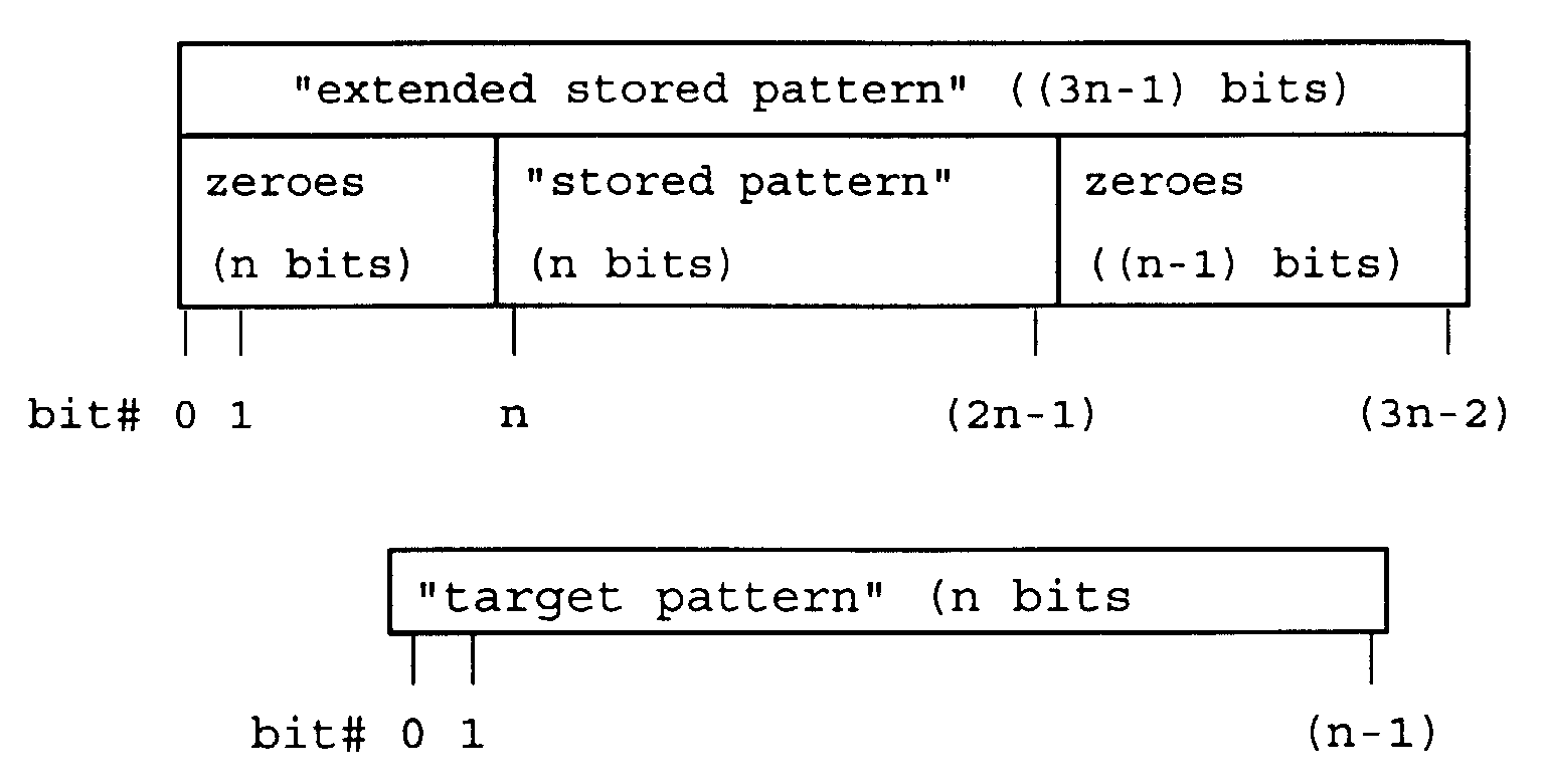
First, create a new pattern by appending n zero bits
to the left and (n-1) zero bits to the right of the "stored
pattern" to form an "extended stored pattern" of length (3n-1).
Then, for each starting bit position from 0 to (2n-1)
in the "extended stored pattern", count the number of bit
positions that differ between the corresponding n bits in the
"extended stored pattern" and the "target pattern". The bit at
the starting bit position in the "extended stored pattern" is
compared to the bit at bit position 0 in the "target pattern".
The minimum number from the previous 2n operations is the
distance between the "stored pattern" and the "target pattern".
Procedure 2.0
To determine the distance between a "stored pattern"
and a "target pattern" if the patterns are equal and of length
(n), determine the distance as if the patterns were not equal
(using Procedure 1.0), but ignore the count operation when the
starting bit position is n. The number of differences when the
starting bit position is n will be zero since this is where the
"stored pattern" and the "target pattern" are equal.
Procedure 3.0
This procedure can be used to determine the distance
for a set of (m) patterns of length (n).
First, determine the distance for each pattern with
the pattern used as both "stored pattern" and "target pattern"
using Procedure 2.0 (m distances will be found).
Then, determine the distance for each pattern with
each pattern used as the "stored pattern" and every other
pattern used as the "target pattern" using Procedure 1.0 (m2-m
distances will be found). The minimum distance between the
first step and the second step is the distance for the set of
patterns.
Example
Consider the example wherein the set of patterns
consists of 001110101, 010110011, 101001101, and 101111011. In
this example, therefore, m=4 and n=9.
First, use Procedure 2.0 with "stored pattern" =
001110101 and "target pattern" = 001110101. The distance is
three.
Next, use Procedure 1.0 with "stored pattern" =
001110101 and "target pattern" = 010110011. Again, the distance
is three.
Finally, use Procedure 1.0 or Procedure 2.0 to fill
each entry in the following matrix with the distance.
| | | Stored Pattern |
| | | 001110101 | 010110011 | 101001101 | 101111011 |
| Target Pattern | 001110101 | 3 | 3 | 3 | 3 |
| 010110011 | 3 | 4 | 3 | 3 |
| 101001101 | 3 | 3 | 3 | 3 |
| 101111011 | 3 | 3 | 3 | 4 |
The minimum from the above matrix (i.e., three in
this case), is the distance for this pattern.
Using these procedures many sets of error tolerant
patterns can be obtained. The number of patterns in a set, the
number of errors allowed, and the number bits in the pattern
can all be traded off to best fit the application.
If two bit error tolerance is required, the following
are examples of some of the possibilities:
| 6 bit pattern - | 6 | sets of 1 pattern |
| 7 bit pattern - | 31 | sets of 1 pattern |
| 8 bit pattern - | 105 | sets of 1 pattern |
| 185 | sets of 2 patterns |
| 8 | sets of 3 patterns |
| 9 bit pattern - | 286 | sets of 1 pattern |
| 6,351 | sets of 2 patterns |
| 20,675 | sets of 3 patterns |
| 10,230 | sets of 4 patterns |
| 631 | sets of 5 patterns |
| 4 | sets of 6 patterns |
If three bit error tolerance is required, the
following are examples of some of the possibilities:
| 8 bit pattern - | 2 | sets of 1 pattern |
| 9 bit pattern - | 42 | sets of 1 pattern |
As discussed above, a preferred embodiment of a
magnetic medium according to the present invention includes
four index marks and, consequently, four predefined bit
patterns. It was determined that, to define a set of four bit
patterns wherein each pattern is a "distance" of three bits
from every other pattern, the bit patterns had to be at least
nine bits in length.
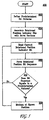
Figure 5 shows a flowchart of a method 400 according
to the present invention for determining a rotational position
of a magnetic storage medium divided into a plurality of servo
sections. According to the inventive method, at step 402, a
predetermined bit pattern is defined that corresponds to a
known position of magnetic storage medium. At step 404, a
rotational position indicator bit is associated with each servo
section such that a known bit of the predetermined bit pattern
is associated with the known position of the magnetic storage
medium. At step 406, a current rotational position indicator
bit is read from the magnetic storage medium and, at step 408,
a rotational position bit sequence comprising the current
rotational position indicator bit is formed. At step 410, the
rotational position bit sequence is compared with the
predetermined bit pattern and, at step 412, based on the
comparison, it is determined whether the magnetic medium is at
the known position.
Those skilled in the art will appreciate that
numerous changes and modifications may be made to the preferred
embodiments of the invention and that such changes and
modifications may be made without departing from the spirit of
the invention. For example, it should be understood that the
number of bit patterns is not limited to four; fewer or more
could be used. Similarly, the length of the patterns is not
limited to nine bits; again, fewer or more could be used. It
is therefore intended that the appended claims cover all such
equivalent variations as fall within the true spirit and scope
of the invention.