EP1076371A1 - Cellule électrolytique secondaire non-aqueuse et son procédé de fabrication - Google Patents
Cellule électrolytique secondaire non-aqueuse et son procédé de fabrication Download PDFInfo
- Publication number
- EP1076371A1 EP1076371A1 EP00117158A EP00117158A EP1076371A1 EP 1076371 A1 EP1076371 A1 EP 1076371A1 EP 00117158 A EP00117158 A EP 00117158A EP 00117158 A EP00117158 A EP 00117158A EP 1076371 A1 EP1076371 A1 EP 1076371A1
- Authority
- EP
- European Patent Office
- Prior art keywords
- current collector
- collector plate
- electrode
- negative electrode
- edge
- Prior art date
- Legal status (The legal status is an assumption and is not a legal conclusion. Google has not performed a legal analysis and makes no representation as to the accuracy of the status listed.)
- Granted
Links
- 239000011255 nonaqueous electrolyte Substances 0.000 title claims abstract description 52
- 238000000034 method Methods 0.000 title claims description 29
- RYGMFSIKBFXOCR-UHFFFAOYSA-N Copper Chemical compound [Cu] RYGMFSIKBFXOCR-UHFFFAOYSA-N 0.000 claims abstract description 61
- 229910052802 copper Inorganic materials 0.000 claims abstract description 57
- 239000010949 copper Substances 0.000 claims abstract description 57
- 229910052751 metal Inorganic materials 0.000 claims abstract description 45
- 239000002184 metal Substances 0.000 claims abstract description 45
- 229910045601 alloy Inorganic materials 0.000 claims abstract description 16
- 239000000956 alloy Substances 0.000 claims abstract description 16
- 238000002310 reflectometry Methods 0.000 claims abstract description 15
- WHXSMMKQMYFTQS-UHFFFAOYSA-N Lithium Chemical compound [Li] WHXSMMKQMYFTQS-UHFFFAOYSA-N 0.000 claims abstract description 11
- 229910052744 lithium Inorganic materials 0.000 claims abstract description 11
- 229910000765 intermetallic Inorganic materials 0.000 claims abstract description 9
- 239000010410 layer Substances 0.000 claims description 135
- 238000003466 welding Methods 0.000 claims description 62
- PXHVJJICTQNCMI-UHFFFAOYSA-N Nickel Chemical compound [Ni] PXHVJJICTQNCMI-UHFFFAOYSA-N 0.000 claims description 55
- 238000003825 pressing Methods 0.000 claims description 35
- 229910052759 nickel Inorganic materials 0.000 claims description 27
- 229910001220 stainless steel Inorganic materials 0.000 claims description 25
- 239000010935 stainless steel Substances 0.000 claims description 24
- 229910052782 aluminium Inorganic materials 0.000 claims description 21
- XAGFODPZIPBFFR-UHFFFAOYSA-N aluminium Chemical compound [Al] XAGFODPZIPBFFR-UHFFFAOYSA-N 0.000 claims description 20
- 238000000576 coating method Methods 0.000 claims description 18
- 239000007788 liquid Substances 0.000 claims description 18
- 239000011248 coating agent Substances 0.000 claims description 17
- 238000010894 electron beam technology Methods 0.000 claims description 11
- 230000001678 irradiating effect Effects 0.000 claims description 11
- 239000011149 active material Substances 0.000 claims description 10
- 230000002093 peripheral effect Effects 0.000 claims description 7
- 238000005096 rolling process Methods 0.000 claims description 7
- 238000004804 winding Methods 0.000 claims description 6
- 239000002344 surface layer Substances 0.000 claims description 4
- 230000000052 comparative effect Effects 0.000 description 20
- HBBGRARXTFLTSG-UHFFFAOYSA-N Lithium ion Chemical compound [Li+] HBBGRARXTFLTSG-UHFFFAOYSA-N 0.000 description 18
- 229910001416 lithium ion Inorganic materials 0.000 description 18
- 239000003792 electrolyte Substances 0.000 description 15
- 238000010276 construction Methods 0.000 description 12
- 238000012360 testing method Methods 0.000 description 10
- 239000007773 negative electrode material Substances 0.000 description 9
- 239000007774 positive electrode material Substances 0.000 description 9
- 230000000694 effects Effects 0.000 description 8
- 238000000429 assembly Methods 0.000 description 6
- 230000000712 assembly Effects 0.000 description 6
- 230000001771 impaired effect Effects 0.000 description 6
- CIWBSHSKHKDKBQ-JLAZNSOCSA-N Ascorbic acid Chemical compound OC[C@H](O)[C@H]1OC(=O)C(O)=C1O CIWBSHSKHKDKBQ-JLAZNSOCSA-N 0.000 description 5
- 239000011889 copper foil Substances 0.000 description 5
- 239000011888 foil Substances 0.000 description 5
- 238000004519 manufacturing process Methods 0.000 description 5
- 238000002844 melting Methods 0.000 description 5
- 230000008018 melting Effects 0.000 description 5
- 239000002033 PVDF binder Substances 0.000 description 4
- 230000003292 diminished effect Effects 0.000 description 4
- 239000000463 material Substances 0.000 description 4
- 239000000203 mixture Substances 0.000 description 4
- 229920002981 polyvinylidene fluoride Polymers 0.000 description 4
- 229910032387 LiCoO2 Inorganic materials 0.000 description 3
- 239000003575 carbonaceous material Substances 0.000 description 3
- 238000009826 distribution Methods 0.000 description 3
- 239000007789 gas Substances 0.000 description 3
- 238000005470 impregnation Methods 0.000 description 3
- 238000002156 mixing Methods 0.000 description 3
- 229910021382 natural graphite Inorganic materials 0.000 description 3
- -1 polyethylene Polymers 0.000 description 3
- 239000010936 titanium Substances 0.000 description 3
- XKRFYHLGVUSROY-UHFFFAOYSA-N Argon Chemical compound [Ar] XKRFYHLGVUSROY-UHFFFAOYSA-N 0.000 description 2
- OKTJSMMVPCPJKN-UHFFFAOYSA-N Carbon Chemical compound [C] OKTJSMMVPCPJKN-UHFFFAOYSA-N 0.000 description 2
- VYZAMTAEIAYCRO-UHFFFAOYSA-N Chromium Chemical compound [Cr] VYZAMTAEIAYCRO-UHFFFAOYSA-N 0.000 description 2
- OIFBSDVPJOWBCH-UHFFFAOYSA-N Diethyl carbonate Chemical compound CCOC(=O)OCC OIFBSDVPJOWBCH-UHFFFAOYSA-N 0.000 description 2
- XTHFKEDIFFGKHM-UHFFFAOYSA-N Dimethoxyethane Chemical compound COCCOC XTHFKEDIFFGKHM-UHFFFAOYSA-N 0.000 description 2
- 229910001290 LiPF6 Inorganic materials 0.000 description 2
- ZOKXTWBITQBERF-UHFFFAOYSA-N Molybdenum Chemical compound [Mo] ZOKXTWBITQBERF-UHFFFAOYSA-N 0.000 description 2
- 239000004743 Polypropylene Substances 0.000 description 2
- RTAQQCXQSZGOHL-UHFFFAOYSA-N Titanium Chemical compound [Ti] RTAQQCXQSZGOHL-UHFFFAOYSA-N 0.000 description 2
- 230000001154 acute effect Effects 0.000 description 2
- IZJSTXINDUKPRP-UHFFFAOYSA-N aluminum lead Chemical compound [Al].[Pb] IZJSTXINDUKPRP-UHFFFAOYSA-N 0.000 description 2
- 238000005452 bending Methods 0.000 description 2
- 239000011230 binding agent Substances 0.000 description 2
- ZPOLOEWJWXZUSP-WAYWQWQTSA-N bis(prop-2-enyl) (z)-but-2-enedioate Chemical compound C=CCOC(=O)\C=C/C(=O)OCC=C ZPOLOEWJWXZUSP-WAYWQWQTSA-N 0.000 description 2
- 239000011651 chromium Substances 0.000 description 2
- 229910052804 chromium Inorganic materials 0.000 description 2
- 239000012141 concentrate Substances 0.000 description 2
- 238000011161 development Methods 0.000 description 2
- 238000010292 electrical insulation Methods 0.000 description 2
- 230000005611 electricity Effects 0.000 description 2
- 230000001747 exhibiting effect Effects 0.000 description 2
- 229910052750 molybdenum Inorganic materials 0.000 description 2
- 239000011733 molybdenum Substances 0.000 description 2
- 238000012856 packing Methods 0.000 description 2
- 229920001155 polypropylene Polymers 0.000 description 2
- 238000002360 preparation method Methods 0.000 description 2
- 239000011877 solvent mixture Substances 0.000 description 2
- 229910052719 titanium Inorganic materials 0.000 description 2
- BUPLCMMXKFWTTA-UHFFFAOYSA-N 4-methylidene-1,3-dioxetan-2-one Chemical compound C=C1OC(=O)O1 BUPLCMMXKFWTTA-UHFFFAOYSA-N 0.000 description 1
- KMTRUDSVKNLOMY-UHFFFAOYSA-N Ethylene carbonate Chemical compound O=C1OCCO1 KMTRUDSVKNLOMY-UHFFFAOYSA-N 0.000 description 1
- 229910012974 LiCo2 Inorganic materials 0.000 description 1
- 229910003005 LiNiO2 Inorganic materials 0.000 description 1
- 229910002097 Lithium manganese(III,IV) oxide Inorganic materials 0.000 description 1
- 239000004698 Polyethylene Substances 0.000 description 1
- 229910052786 argon Inorganic materials 0.000 description 1
- 229910021383 artificial graphite Inorganic materials 0.000 description 1
- 229910000963 austenitic stainless steel Inorganic materials 0.000 description 1
- 238000009835 boiling Methods 0.000 description 1
- 229910052799 carbon Inorganic materials 0.000 description 1
- 239000000571 coke Substances 0.000 description 1
- 239000002131 composite material Substances 0.000 description 1
- 150000001875 compounds Chemical class 0.000 description 1
- 239000006258 conductive agent Substances 0.000 description 1
- 239000011530 conductive current collector Substances 0.000 description 1
- 239000004020 conductor Substances 0.000 description 1
- 230000007797 corrosion Effects 0.000 description 1
- 238000005260 corrosion Methods 0.000 description 1
- 238000005520 cutting process Methods 0.000 description 1
- 230000003247 decreasing effect Effects 0.000 description 1
- 230000006735 deficit Effects 0.000 description 1
- IEJIGPNLZYLLBP-UHFFFAOYSA-N dimethyl carbonate Chemical compound COC(=O)OC IEJIGPNLZYLLBP-UHFFFAOYSA-N 0.000 description 1
- 238000010294 electrolyte impregnation Methods 0.000 description 1
- KLKFAASOGCDTDT-UHFFFAOYSA-N ethoxymethoxyethane Chemical compound CCOCOCC KLKFAASOGCDTDT-UHFFFAOYSA-N 0.000 description 1
- 238000002474 experimental method Methods 0.000 description 1
- 229910002804 graphite Inorganic materials 0.000 description 1
- 239000010439 graphite Substances 0.000 description 1
- MHCFAGZWMAWTNR-UHFFFAOYSA-M lithium perchlorate Chemical compound [Li+].[O-]Cl(=O)(=O)=O MHCFAGZWMAWTNR-UHFFFAOYSA-M 0.000 description 1
- 229910001486 lithium perchlorate Inorganic materials 0.000 description 1
- 229910001105 martensitic stainless steel Inorganic materials 0.000 description 1
- 238000005259 measurement Methods 0.000 description 1
- 239000012528 membrane Substances 0.000 description 1
- 150000002739 metals Chemical class 0.000 description 1
- 239000005486 organic electrolyte Substances 0.000 description 1
- 239000003960 organic solvent Substances 0.000 description 1
- 229920000573 polyethylene Polymers 0.000 description 1
- 230000002035 prolonged effect Effects 0.000 description 1
- RUOJZAUFBMNUDX-UHFFFAOYSA-N propylene carbonate Chemical compound CC1COC(=O)O1 RUOJZAUFBMNUDX-UHFFFAOYSA-N 0.000 description 1
- 238000007789 sealing Methods 0.000 description 1
- 239000002356 single layer Substances 0.000 description 1
- 239000002904 solvent Substances 0.000 description 1
- 239000000126 substance Substances 0.000 description 1
Images








Classifications
-
- H—ELECTRICITY
- H01—ELECTRIC ELEMENTS
- H01M—PROCESSES OR MEANS, e.g. BATTERIES, FOR THE DIRECT CONVERSION OF CHEMICAL ENERGY INTO ELECTRICAL ENERGY
- H01M4/00—Electrodes
- H01M4/02—Electrodes composed of, or comprising, active material
- H01M4/64—Carriers or collectors
- H01M4/66—Selection of materials
- H01M4/661—Metal or alloys, e.g. alloy coatings
-
- H—ELECTRICITY
- H01—ELECTRIC ELEMENTS
- H01M—PROCESSES OR MEANS, e.g. BATTERIES, FOR THE DIRECT CONVERSION OF CHEMICAL ENERGY INTO ELECTRICAL ENERGY
- H01M10/00—Secondary cells; Manufacture thereof
- H01M10/04—Construction or manufacture in general
- H01M10/0431—Cells with wound or folded electrodes
-
- H—ELECTRICITY
- H01—ELECTRIC ELEMENTS
- H01M—PROCESSES OR MEANS, e.g. BATTERIES, FOR THE DIRECT CONVERSION OF CHEMICAL ENERGY INTO ELECTRICAL ENERGY
- H01M10/00—Secondary cells; Manufacture thereof
- H01M10/05—Accumulators with non-aqueous electrolyte
- H01M10/052—Li-accumulators
- H01M10/0525—Rocking-chair batteries, i.e. batteries with lithium insertion or intercalation in both electrodes; Lithium-ion batteries
-
- H—ELECTRICITY
- H01—ELECTRIC ELEMENTS
- H01M—PROCESSES OR MEANS, e.g. BATTERIES, FOR THE DIRECT CONVERSION OF CHEMICAL ENERGY INTO ELECTRICAL ENERGY
- H01M10/00—Secondary cells; Manufacture thereof
- H01M10/05—Accumulators with non-aqueous electrolyte
- H01M10/058—Construction or manufacture
- H01M10/0587—Construction or manufacture of accumulators having only wound construction elements, i.e. wound positive electrodes, wound negative electrodes and wound separators
-
- H—ELECTRICITY
- H01—ELECTRIC ELEMENTS
- H01M—PROCESSES OR MEANS, e.g. BATTERIES, FOR THE DIRECT CONVERSION OF CHEMICAL ENERGY INTO ELECTRICAL ENERGY
- H01M50/00—Constructional details or processes of manufacture of the non-active parts of electrochemical cells other than fuel cells, e.g. hybrid cells
- H01M50/50—Current conducting connections for cells or batteries
- H01M50/531—Electrode connections inside a battery casing
- H01M50/533—Electrode connections inside a battery casing characterised by the shape of the leads or tabs
-
- H—ELECTRICITY
- H01—ELECTRIC ELEMENTS
- H01M—PROCESSES OR MEANS, e.g. BATTERIES, FOR THE DIRECT CONVERSION OF CHEMICAL ENERGY INTO ELECTRICAL ENERGY
- H01M50/00—Constructional details or processes of manufacture of the non-active parts of electrochemical cells other than fuel cells, e.g. hybrid cells
- H01M50/50—Current conducting connections for cells or batteries
- H01M50/531—Electrode connections inside a battery casing
- H01M50/534—Electrode connections inside a battery casing characterised by the material of the leads or tabs
-
- H—ELECTRICITY
- H01—ELECTRIC ELEMENTS
- H01M—PROCESSES OR MEANS, e.g. BATTERIES, FOR THE DIRECT CONVERSION OF CHEMICAL ENERGY INTO ELECTRICAL ENERGY
- H01M50/00—Constructional details or processes of manufacture of the non-active parts of electrochemical cells other than fuel cells, e.g. hybrid cells
- H01M50/50—Current conducting connections for cells or batteries
- H01M50/531—Electrode connections inside a battery casing
- H01M50/536—Electrode connections inside a battery casing characterised by the method of fixing the leads to the electrodes, e.g. by welding
-
- H—ELECTRICITY
- H01—ELECTRIC ELEMENTS
- H01M—PROCESSES OR MEANS, e.g. BATTERIES, FOR THE DIRECT CONVERSION OF CHEMICAL ENERGY INTO ELECTRICAL ENERGY
- H01M50/00—Constructional details or processes of manufacture of the non-active parts of electrochemical cells other than fuel cells, e.g. hybrid cells
- H01M50/50—Current conducting connections for cells or batteries
- H01M50/531—Electrode connections inside a battery casing
- H01M50/538—Connection of several leads or tabs of wound or folded electrode stacks
-
- H—ELECTRICITY
- H01—ELECTRIC ELEMENTS
- H01M—PROCESSES OR MEANS, e.g. BATTERIES, FOR THE DIRECT CONVERSION OF CHEMICAL ENERGY INTO ELECTRICAL ENERGY
- H01M10/00—Secondary cells; Manufacture thereof
- H01M10/05—Accumulators with non-aqueous electrolyte
-
- Y—GENERAL TAGGING OF NEW TECHNOLOGICAL DEVELOPMENTS; GENERAL TAGGING OF CROSS-SECTIONAL TECHNOLOGIES SPANNING OVER SEVERAL SECTIONS OF THE IPC; TECHNICAL SUBJECTS COVERED BY FORMER USPC CROSS-REFERENCE ART COLLECTIONS [XRACs] AND DIGESTS
- Y02—TECHNOLOGIES OR APPLICATIONS FOR MITIGATION OR ADAPTATION AGAINST CLIMATE CHANGE
- Y02E—REDUCTION OF GREENHOUSE GAS [GHG] EMISSIONS, RELATED TO ENERGY GENERATION, TRANSMISSION OR DISTRIBUTION
- Y02E60/00—Enabling technologies; Technologies with a potential or indirect contribution to GHG emissions mitigation
- Y02E60/10—Energy storage using batteries
-
- Y—GENERAL TAGGING OF NEW TECHNOLOGICAL DEVELOPMENTS; GENERAL TAGGING OF CROSS-SECTIONAL TECHNOLOGIES SPANNING OVER SEVERAL SECTIONS OF THE IPC; TECHNICAL SUBJECTS COVERED BY FORMER USPC CROSS-REFERENCE ART COLLECTIONS [XRACs] AND DIGESTS
- Y02—TECHNOLOGIES OR APPLICATIONS FOR MITIGATION OR ADAPTATION AGAINST CLIMATE CHANGE
- Y02P—CLIMATE CHANGE MITIGATION TECHNOLOGIES IN THE PRODUCTION OR PROCESSING OF GOODS
- Y02P70/00—Climate change mitigation technologies in the production process for final industrial or consumer products
- Y02P70/50—Manufacturing or production processes characterised by the final manufactured product
-
- Y—GENERAL TAGGING OF NEW TECHNOLOGICAL DEVELOPMENTS; GENERAL TAGGING OF CROSS-SECTIONAL TECHNOLOGIES SPANNING OVER SEVERAL SECTIONS OF THE IPC; TECHNICAL SUBJECTS COVERED BY FORMER USPC CROSS-REFERENCE ART COLLECTIONS [XRACs] AND DIGESTS
- Y10—TECHNICAL SUBJECTS COVERED BY FORMER USPC
- Y10T—TECHNICAL SUBJECTS COVERED BY FORMER US CLASSIFICATION
- Y10T29/00—Metal working
- Y10T29/49—Method of mechanical manufacture
- Y10T29/49002—Electrical device making
- Y10T29/49108—Electric battery cell making
- Y10T29/49114—Electric battery cell making including adhesively bonding
Definitions
- the present invention relates to nonaqueous electrolyte secondary cells, such as cylindrical lithium ion secondary cells, which comprise an electrode unit encased in a battery can and serving as an electricity generating element and which are adapted to deliver the electricity generated by the electrode unit to the outside via a positive terminal portion and a negative terminal portion like.
- the invention relates also to processes for fabricating such cells.
- Nonaqueous electrolyte secondary cells of the type mentioned comprise a rolled-up electrode unit formed by laying a positive electrode and a negative electrode, each in the form of a strip, over each other in layers with a separator interposed therebetween and rolling up the resulting assembly into a spiral form.
- the rolled-up electrode unit is encased in a battery can.
- the electric power generated by the rolled-up electrode unit is delivered to the outside through an arrangement including a plurality of conductive current collector tabs having their base ends attached to each of the positive electrode and the negative electrode of the electrode unit.
- the positive current collector tabs extending from the positive electrode have outer ends connected to a positive terminal portion
- the negative current collector tabs extending from the negative electrode have outer ends connected to a negative terminal portion. This arrangement is widely used.
- the current collecting arrangement comprising a plurality of collector tabs has the problem of failing to achieve a sufficient current collecting effect when used in nonaqueous electrolyte secondary cells of large size having a high current value since the cell has increased electrode areas although producing a satisfactory current collecting effect in nonaqueous electrolyte secondary cells of small size which are relatively low in current value.
- connection of the current collector tabs to each electrode terminal portion requires a complex structure and complicated procedure, hence the problem of low work efficiency or productivity.
- a cylindrical nonaqueous electrolyte secondary cell which has a current collecting structure comprising a negative electrode current collector plate 36 and a positive electrode current collector plate 30 as shown in FIG. 7.
- This cell has a battery can 1 formed by a cylinder 15 and lids 16, 16 secured to opposite open ends of the cylinder.
- a rolled-up electrode unit 2 is enclosed in the battery can 1.
- the negative electrode collector plate 36 and the positive electrode collector plate 30 are arranged at respective ends of the electrode unit 2 and joined to the unit 2 by laser welding.
- the collector plates 36, 30 are connected by lead portions 37, 34 respectively to a negative terminal assembly 4 and a positive terminal assembly 40 mounted on lids 16, 16.
- the rolled-up electrode unit 2 comprises a positive electrode 23, separator 22 and negative electrode 21 each in the form of a strip.
- the positive electrode 23 is formed by coating a current collector of aluminum foil with a positive electrode active material.
- the negative electrode 21 is formed by coating a current collector of copper foil with a negative electrode active material.
- the positive electrode 23 and the negative electrode 21 are each superposed on the separator 22, as displaced from the separator widthwise thereof and rolled up into a spiral form, whereby the edge of the positive electrode 23 is positioned as projected outward beyond the edge of the separator 22 at one of opposite ends of the electrode unit 2 in the direction of its winding axis, and the edge of the negative electrode 21 is positioned as projected outward beyond the edge of the separator 22 at the other end of the unit 2.
- the positive electrode current collector plate 30 is made of aluminum, and the negative current collector plate 36 is made of copper.
- the collector plates 36, 30 are joined to the respective ends of the electrode unit 2 as described above, the collector plates can be welded to the unit 2 contactlessly without applying pressure to the plates for welding. This achieves an improved work efficiency or productivity.
- FIGS. 20 and 23 show another conventional nonaqueons electrolyte secondary cell, which comprises a cylindrical battery can 1 including a cylinder 15 and lids 16, 16 welded to respective opposite ends of the cylinder, and a rolled-up electrode unit 5 enclosed in the can 1.
- a pair of positive and negative terminal assemblies 110, 110 are mounted on the respective lids 16, 16 and each connected to the electrode unit 5 by a plurality of electrode tabs 6 for delivering the electric power generated by the unit 5 to the outside through the terminal assemblies 110, 110.
- Each lid 6 is provided with a gas vent valve 13 which is openable with pressure.
- the rolled-up electrode unit 5 comprises a positive electrode 51 and a negative electrode 52 each in the form of a strip and rolled up into a spiral form with a striplike separator 52 interposed between the electrodes.
- the positive electrode 51 is prepared by coating opposite surfaces of a striplike current collector 55 of aluminum foil with a positive electrode active material 54 comprising a lithium containing composite oxides.
- the negative electrode 53 is prepared by coating opposite surfaces of a striplike current collector 57 of copper foil with a negative electrode active material 56 containing a carbon material.
- the separator 52 is impregnated with a nonaqueous electrolyte.
- the positive electrode 51 has an uncoated portion having no active material 54 applied thereto, and base ends of the electrode tabs 6 are joined to the uncoated portion.
- the negative electrode 53 has an uncoated portion having no active material 56 applied thereto, and base ends of the electrode tabs 6 are joined to the uncoated portion.
- the electrode tabs 6 of the same polarity have outer ends 61 connected to one electrode terminal assembly 110.
- FIG. 23 shows only some of the electrode tabs as connected at their outer ends to the terminal assembly 110, with the connection of the other tab outer ends to the assembly 110 omitted from the illustration.
- the electrode terminal assembly 110 comprises an electrode terminal 111 extending through and attached to the lid 16 of the battery can 1.
- the electrode terminal 111 has a base end formed with a flange 112.
- the hole in the lid 16 for the terminal 111 to extend therethrough has an insulating packing 113 fitted therein to provide electrical insulation and a seal between the lid 16 and fastening members.
- the terminal 111 has a washer 114 fitted therearound from outside the lid 16, and a first nut 115 and a second nut 116 which are screwed thereon.
- the insulating packing 113 is clamped between the flange 112 of the terminal 111 and the washer 114 by tightening up the first nut 115 to produce an enhanced sealing effect.
- the outer ends 61 of the electrode tabs 6 are secured to the flange 112 of the terminal 111 by spot welding or ultrasonic welding.
- Lithium ion secondary cells have the problem that an increase in the size thereof lengthens the positive and negative electrodes, consequently lowering the current collecting efficiency of the current collecting structure comprising electrode tabs to produce variations in internal resistance or result in a lower discharge capacity.
- FIG. 21 shows a current collecting structure proposed to obtain a uniform current collecting efficiency over the entire lengths of the positive and negative electrodes.
- the proposed structure is provided for a rolled-up electrode unit 7, which comprises a positive electrode 71 prepared by coating a current collector 75 with a positive electrode active material 74, a negative electrode 73 formed by coating a current collector 77 with a negative electrode active material 76 and a separator 72 impregnated with a nonaqueous electrolyte.
- the positive electrode 71 and the negative electrode 73 are each superposed on the separator 72 as displaced widthwise of the separator, and rolled up into a spiral form, whereby the edge 78 of current collector 75 of the positive electrode 71 is positioned as projected outward beyond the edge of the separator 72 at one of opposite ends of the electrode unit 7 in the direction of its winding axis, and the edge 78 of current collector 77 of the negative electrode 73 is positioned as projected outward beyond the edge of the separator 72 at the other end of the unit 7.
- a disklike current collector plate 62 is secured to each of opposite ends of the rolled-up electrode unit 7 by resistance welding and connected to the same electrode terminal assembly 110 as described above by a lead member 63.
- lithium ion secondary cells for example, for use as power sources in electric motor vehicles be of high capacity and reduced in internal resistance to the greatest possible extent so as to obtain a high power. Furthermore a current collecting structure of high productivity is required for a reduction of manufacturing cost.
- a cell of low resistance and high productivity which comprises a current collector plate having small bulging portions formed thereon as uniformly distributed over the entire surface thereof, such that the collector plate is secured to a current collector edge by resistance welding with the bulging portions in contact therewith to concentrate the current on the bulging portions and give improved weld strength (see, for example, JP-U No. 156365/1980).
- a current collecting structure which comprises a current collector plate 92 prepared by forming a plurality of bent portions 94 on a flat platelike body 93, the bent portions 94 being secured to a current collector edge 78 of a rolled-up electrode unit 7 by resistance welding with the collector plate 92 pressed against the current collector edge 78 (see, for example, JP-A No. 31497/1999).
- JP-A No. 29564/1995 a current collector plate comprising two divided segments for suppressing ineffective current involved in attaching the collector plate by resistance welding to achieve an improved welding efficiency
- JP-B No. 8417/1990 a current collector plate having a projection V-shaped in section and formed on the portion thereof to be joined by resistance welding so as to concentrate the welding current on the projection and afford improved weld strength
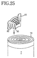
- a current collecting structure comprising a current collector member 95 in place of the disklike collector plate and formed with a plurality of slits 96 as seen in FIG. 25.
- a laser beam is projected onto the surface of the collector member 95 as disposed at an end of a rolled-up electrode unit 7, with a current collector edge 78 fitted in the slits 96 of the member 95 (JP-A No. 261441/1998).
- a disklike current collector plate has a plurality of projections, V-shaped in section and up to 90° in end angle, and is welded to a group of electrode plates by irradiating the projections with a laser beam, with the collector plate pressed against each current collector (JP-B No. 4102/1990).
- the current collecting structure wherein the current collector plate has projections which are V-shaped in section or bent portions for the resistance welding of the plate (JP-A No. 31497/1999, No. 29564/1995 or JP-B No. 8417/1990) has the problem of low weld strength when the current collector has a very small thickness as is the case with lithium ion secondary cells.
- the current collecting structure wherein the current collector member having a plurality of slits is secured to the current collector edge by laser welding not only requires the collector member which has a complex shape but also has the problem that the work of inserting the current collector edge into the slits of the collector member is very cumbersome.
- the projections have a V-shaped section of acute angle, so that the area of contact between the projection and the current collector edge is small, consequently entailing the problem of increased contact resistance. Since the junction between the V-shaped projection and the current collector edge is at an acute angle with the direction of projection of the laser beam for irradiating the junction, the laser beam fails to act effectively to weld the junction and is likely to produce a faulty weld.
- a first object of the present invention is to provide the construction of a nonaqueous electrolyte secondary cell having a current collecting structure wherein a negative electrode current collector plate is secured to an end of an electrode unit by welding, and to provide a process for fabricating the cell, the collector plate having improved weldability to the electrode unit.
- a second object of the invention is to provide a nonaqueous electrolyte secondary cell having a current collecting structure which is high in productivity and which is so adapted that even when a current collector forming an electrode unit is very thin, an edge of the current collector can be joined to a current collector plate over an increased area of contact, and a process for fabricating the cell.
- the present invention provides a nonaqueous electrolyte secondary cell comprising an electrode unit 2 which includes a negative electrode 21 having a projecting edge at one of opposite ends of the electrode unit in the direction of winding axis thereof.
- a negative electrode current collector plate 3 is joined to the edge and electrically connected to a negative terminal portion.
- the collector plate 3 comprises a plurality of layers including a copper layer 31 made of copper or an alloy consisting predominantly of copper, and a metal layer made of a metal not forming an intermetallic compound with lithium and having a lower laser beam reflectivity than copper or an alloy consisting predominantly of the metal.
- the copper layer 31 and the metal layer provide opposite surface layers of the collector plate 3, and the copper layer 31 is welded to the edge of the negative electrode 21.
- the metal for forming the metal layer of the negative electrode current collector plate 3 is, for example, nickel, stainless steel, titanium, chromium or molybdenum.
- the laser beam can be sufficiently absorbed by the collector plate 3 for perfect welding since the laser beam impinging side of the plate 3 is provided by the metal layer which is low in laser beam reflectivity.
- the metal layer of the collector plate 3 is made of a metal not forming an intermetallic compound with lithium or an alloy consisting predominantly of the metal and is therefore unlikely to consume lithium ions in the nonaqueous electrolyte to form an alloy, consequently precluding the lithium ion concentration of the nonaqueous electrolyte from reducing.
- the negative electrode current collector plate 3 comprises a plurality of layers, i.e., the copper layer 31 and the metal layer, the high conductivity of the copper layer gives the plate 3 lower electric resistance and higher electric conductivity than when the plate 3 consists solely of the metal layer.
- the edge of the negative electrode 21 of the electrode unit 2 is joined to the copper layer 31 of the collector plate 3 over the entire length thereof, consequently making it possible to collect the current from the entire electrode unit 2 uniformly even if the cell is large-sized with an increase in the length of the electrodes. This reduces the potential gradient along the length of the negative electrode 21, giving a uniform current distribution, whereby a high current collecting efficiency can be achieved.
- the negative electrode current collector plate 3 has a thickness in the range of 0.10 mm to 5.00 mm. If the thickness is smaller than 0.10 mm, the collector plate 3 itself has increased electric resistance, which not only results in a lower current collecting efficiency but also permits the collector plate 3 to become melted to excess by laser welding to produce a cave-in in the weld. If the thickness is in excess of 5.00 mm, on the other hand, welding of the collector plate 3 requires increased power, presenting difficulty in welding the collector plate 3 to the negative electrode edge which is tens of micrometers in thickness.
- the ratio of the thickness of the metal layer to the thickness of the negative electrode current collector plate 3 is in the range of at least 5% to not greater than 45%. This enables the metal layer to fully serve the function of exhibiting reduced laser beam reflectivity, also permitting the copper layer 31 to satifactorily perform the function of exhibiting reduced electric resistance. If the ratio is smaller than 5%, the metal layer disappears on melting immediately after the start of welding of the collector plate 3 to expose a surface of high laser beam reflectivity, hence impaired weldability. When the ratio is in excess of 45%, on the other hand, the metal layer becomes predominant with respect to the electric resistance of the collector plate 3, increasing the overall electric resistance of the plate 3.
- the present invention further provides a process for fabricating a nonaqueous electrolyte secondary cell which process has the steps of:
- the laser beam is projected on the surface of the metal layer of low reflectivity, so that the energy of the laser beam can be fully given to the junction of the collector plate 3 and the edge of the negative electrode 21, consequently welding the plate 3 and the negative electrode edge to each other completely.
- the aluminum forming the collecting plate 30 is low in laser beam reflectivity, so that the energy of the laser beam can be fully given to the junction of the collector plate 30 and the edge of the positive electrode 23, consequently welding the plate 30 and the positive electrode edge to each other completely.
- the positive electrode current collector plate 30 and the negative electrode current collector plate 3 are electrically connected to the positive terminal portion and the negative terminal portion, respectively.
- the nonaqueous electrolyte secondary cell and the process for fabricating the cell according to the invention give the negative electrode current collector plate improved weldability to the electrode unit, whereby a high current collecting efficiency can be attained as described above.
- Another nonaqueous electrolyte secondary cell comprises an electrode unit 7 encased in a battery can 1 and comprising as superposed in layers a positive electrode 71, a negative electrode 73 and a separator 72 interposed between the electrodes and impregnated with a nonaqueous electrolyte, each of the positive electrode 71 and the negative electrode 73 being formed by coating a striplike current collector with an active material.
- the cell is adapted to deliver electric power generated by the electrode unit 7 to the outside via a pair of electrode terminals.
- the current collector of the positive electrode 71 or the negative electrode 73 has a projecting edge 78 at at least one of opposite ends of the electrode unit 7, and a current collector plate 8 is joined to the edge 78 and has a plurality of protrusions 82 formed on a surface thereof opposed to the current collector edge 78.
- Each of the protrusions is shaped to have a circular-arc section or polygonal (e.g., trapezoidal) section with at least four corners, the collector plate 8 being welded to the current collector edge 78 with the protrusions 82 forced therein and being connected to one of the electrode terminals.
- the present invention further provides a process for fabricating a nonaqueous electrolyte secondary cell which process has the steps of:
- the current collector plate 8 is pressed against the current collector edge 78 of the electrode unit 7, whereby each protrusion 82 of the collector plate 8 is forced or wedged into the current collector edge 78, forming a joint face in the current collector edge 78 in conformity with the contour of the protrusion 82, for example, a cylindrical joint face.
- the joint face has a larger area than is formed by a protrusion which is V-shaped in section.
- the collector plate 8 when the collector plate 8 is welded to the current collector edge 78 by irradiating the junction of each protrusion 82 and the current collector edge 78 with a laser beam or electron beam, the plate 8 is joined to the current collector edge 78 over a large area of contact. This results in diminished contact resistance and a higher current collecting efficiency.
- junction of the collector plate protrusion 82 and the current collector edge 78 will be positioned at 90° or approximately at this angle with the direction of projection of the beam at the midportion of the junction, so that the laser beam or electron beam acts effectively for welding the junction, consequently affording a high weld strength due to the large area of the junction.
- the current collector plate 8 comprises a flat platelike body 81 formed with the protrusions 82 and one or a plurality of liquid inlets 83, and the opening area provided by the liquid inlets 83 is at least 15% of the flat area of the body.
- the opening ratio provided by the liquid inlets 83 is smaller than 15%, the electrolyte encounters difficulty in passing through the collector plate 8 and therefore requires a prolonged period of time for impregnation.
- the opening ratio given by the liquid inlets 83 is in excess of 90%, the current path becomes greatly constricted, increasing the electric resistance of the collector plate 8 and leading to a lower current collecting efficiency. Accordingly, it is desirable that the opening ratio given by the liquid inlets 83 be in the range of 15% to 90%.
- the current collector plate 8 comprises a flat platelike body 81 formed with the protrusions 82 and integrally provided with a striplike lead portion 85, the lead portion 85 having an outer end connected to the electrode terminal.
- the lead portion 85 of this structure is easily connectable to the electrode terminal, further serving to diminish the electric resistance between the electrode unit 7 and the electrode terminal.
- a current collector plate 100 of another structure comprises a flat platelike body 101 provided at an outer peripheral portion thereof with a current collector pressing portion 106 positioned in the vicinity of each protrusion 102 for pressing an end portion of the current collector 77 of the electrode unit 7 inwardly of the electrode unit 7.
- the end portion of the current collector 77 is deflected inwardly of the electrode unit 7 by being pressed by the current collector pressing portion 106, whereby the position of contact of the current collector end with the protrusion 102 of the collector plate 100 is shifted also inwardly of the electrode unit 7.
- the laser beam or electron beam need not be projected onto the radial outer end of the protrusion but the protrusion needs only to be irradiated up to a position slightly inwardly of its outer end, i.e., up to the position where the deflected portion of the current collector 77 is in contact with the protrusion.
- the pressing face of the current collector pressing portion 106 for the current collector 77 and the surface of the platelike body 101 of the collector plate 100 make an angle in the range of at least 30° to not greater than 45°.
- the angle is limited to this range, the outer end of the current collector 77 can be effectively deflected inwardly of the electrode unit 7.
- the protrusions 82 of the collector plate 8 have a width at least 0.8 times the diameter of the spot of the laser beam or electron beam.
- the protrusion 82 of the collector plate 8 has a semicircular form in section, it is desired that the diameter of the semicircle be at least 0.8 times the spot diameter of the laser beam or electron beam.
- the collector plate protrusion 82 has a trapezoidal form in section, it is desired that the width of the upper side (short side) of the trapezoid be at least 0.8 times the spot diameter of the laser beam or electron beam. This enables the laser beam or electron beam to give energy concentrically on the junction of the collector plate protrusion 82 and the current collector edge 78, fully melting the portions to be joined and giving a large joint area and high weld strength.
- the distance the protrusion 82 of the collector plate 8 projects is preferably at least 0.5 mm to not greater than 3 mm. If the distance of projection of the protrusion 82 is smaller than 0.5 mm, it is impossible to force the protrusion 82 into all turns of the current collector at the edge 78 in the case where the edge portions 78 of turns of the current collector of the electrode unit 7 are not positioned uniformly in a plane, consequently failing to afford sufficient weld strength. Further when the distance of projection of the protrusion 82 is in excess of 3 mm, the effect to improve the weld strength will level off, while a greater dead space is created in the interior of the battery can 1 to entail a lower energy density relative to the volume.
- the thickness of the current collector plate 8 is preferably at least 0.1 mm to not greater than 2 mm. If the thickness is smaller than 0.1 mm, the collector plate 8 has increased electric resistance to exhibit a lower current collecting efficiency. Further if the thickness is greater than 2 mm, the effect to improve the current collecting efficiency levels off, while the lead portion 85 formed integrally with the plate 8 will not be workable without a problem.
- the wall thickness of the protrusion 82 of the current collector plate 8 be smaller than the thickness of the flat platelike body 81.
- the flat portion then has a greater thickness, ensuring a satisfactory current collecting efficiency without impairment, while the portion to be irradiated with a beam has a small thickness and therefore permits welding with low energy.
- Usable as the material for the current collector plate 8 is Cu, Al, Ni, SUS, Ti or an alloy of such metals. Use of these materials provides cells which are excellent in corrosion resistance to nonaqueous electrolytes and in conductivity.
- the current collector plate can be joined to the current collector edge over a large contact area even if the current collector forming the electrode unit has a very small thickness as described above, hence high productivity.
- the cylindrical lithium ion secondary cell of this embodiment comprises a battery can 1 formed by fixing lids 16, 16 to opposite open ends of a cylinder 15.
- a rolled-up electrode unit 2 is encased in the battery can 1.
- Arranged respectively at opposite ends of the electrode unit 2 are a negative electrode current collector plate 3 and a positive electrode current collector plate 30 each comprising two layers, i.e., a copper layer 31 and a metal layer made of a metal not forming an intermetallic compound with lithium and having a lower laser beam reflectivity than copper or an alloy consisting predominantly of the metal.
- Each collector plate is welded to the end of the unit 2 with a laser beam
- the collector plates 3 and 30 are connected by respective lead portions 33, 34 to a negative terminal assembly 4 and a positive terminal assembly 40 mounted on the lids 16, 16.
- the rolled-up electrode unit 2 comprises a positive electrode 23, separator 22 and negative electrode 21 each in the form of a strip.
- the positive electrode 23 is formed by coating a current collector of aluminum foil with a positive electrode active material 26 comprising LiCoO 2 .
- the negative electrode 21 is formed by coating a current collector of copper foil with a negative electrode active material 24 comprising natural graphite.
- the positive electrode 23 and the negative electrode 21 are each superposed on the separator 22 as displaced widthwise thereof and are rolled up into a spiral form, whereby an edge (uncoated portion 25) of the rolled-up negative electrode 21 is positioned as projected outward beyond the edge of the separator 22 at one of opposite ends of the electrode unit 2 in the direction of its winding axis, and an edge (uncoated portion 27) of the rolled-up positive electrode 23 is positioned as projected outward beyond the edge of the separator 22 at the other end of the unit 2.
- the active material coatings 24, 26 of the electrodes can be tens of millimeters in width A, the uncoated portions 25, 27 about 10 mm in width B, and the distance S of projection beyond the separator 22 about 1 to about 3 mm.
- the negative electrode current collector plate 3 is in the form of a disk and has a two-layer structure, i.e., a copper layer 31 having a thickness of 2.40 mm and a nickel layer 32 having a thickness of 0.60 mm and made from nickel which is a metal not forming an intermetallic compound with lithium and having a lower laser beam reflectivity than copper.
- the lead portion 33 which is made of copper, extends from an end portion of the collector plate 3.
- Also usable as the collector plate 3 is one having the same structure as above except that the nickel layer 32 is replaced by a stainless steel layer 35 as seen in FIG. 5.
- a negative electrode current collector plate 3 having a three-layer structure, i.e., a copper layer 31 and a nickel layer 32 providing opposite surface layers and a stainless steel layer 39 sandwiched between the two layers.
- the nickel layer 32 or stainless steel layer 35 can be replaced by a layer of a metal, such as titanium layer, chromium layer or molybdenum layer, insofar as the metal forms no intermetallic compound with lithium and has a lower laser beam reflectivity than copper.
- the positive current collector plate 30 is similarly in the form of a disk, made from an aluminum plate having a thickness of 1.00 mm and provided with the lead portion 34 which is made of aluminum.
- the negative electrode current collector plate 3 is disposed at one end of the electrode unit 2 with the copper layer 31 in contact with the edge (uncoated portion 25) of the negative electrode 21 of the unit 2, and is welded to the edge of the negative electrode 21 by being irradiated with a laser beam over the surface of the nickel layer 32.
- the positive electrode current collector plate 30 is disposed likewise at the other end of the electrode unit 2 and welded to the edge of the positive electrode 23 by being irradiated with a laser beam over the surface thereof.
- the negative terminal assembly 4 comprises a terminal member 41 having a screw shank 42 and a flange 43 projecting from the lower end of the shank 42.
- the screw shank 42 of the terminal member 41 extends through the lid 16, and a first insulating member 45 and a second insulating member 46 are fitted around the terminal member 41 to provide electrical insulation and a seal between the lid 16 and the terminal member 41.
- the terminal member 41 has a washer 47 fitted therearound and a nut 48 screwed on its outer end.
- the positive terminal assembly 40 also has the same construction as the assembly 4.
- the lead portion 33 extending from the collector plate 3 has its outer end welded to the flange 43 of terminal member 41 of the negative terminal assembly 4.
- the lead portion 34 extending from the positive collector plate 30 has its outer end welded to the flange 43 of terminal member 41 of the positive terminal assembly 40.
- the lithium ion secondary cell of the present invention is fabricated by the process to be described below.
- a positive electrode 23 is prepared by mixing together a positive electrode active material comprising LiCoO 2 , an auxiliary conductive agent comprising carbon and a binder comprising polyvinylidene fluoride (PVdF) to obtain a positive electrode composition and coating opposite surfaces of a current collector in the form of a strip of aluminum foil with the composition as shown in FIG. 4.
- the positive electrode current collector has one edge portion left uncoated with the active material layer to provide an uncoated portion 27 of 10 mm in width.
- a negative electrode 21 is prepared by mixing together a negative electrode active material comprising natural graphite and a binder comprising polyvinylidene fluoride (PVdF) to obtain a negative electrode composition and coating opposite surfaces of a current collector in the form of a strip of copper foil with the composition.
- the negative electrode current collector has one edge portion left uncoated with the active material layer to provide an uncoated portion 25 of 10 mm in width.
- separator 22 having a width slightly larger than the width A of the coated portion of the positive electrode and the coated portion of the negative electrode.
- the separator 22 is made from porous polyethylene and polypropylene.
- the positive electrode 23, separator 22 and negative electrode 21 are thereafter laid over one another and rolled up into a spiral form as shown in FIG. 4 to obtain a rolled-up electrode unit 2. At this time, these components are arranged in layers so that the edges of the positive electrode uncoated portion 27 and the negative electrode uncoated portion 25 are positioned as projected outward beyond the respective edges of the separator 22.
- a negative electrode current collector plate 3 of two-layer structure is prepared which comprises a copper layer 31 with a thickness of 2.40 mm and a nickel layer 32 with a thickness of 0.60 mm as shown in FIG. 2.
- a negative electrode current collector plate 3 of two-layer structure comprising a stainless steel layer 35 as seen in FIG. 5, or a negative electrode current collector plate 3 of three-layer structure comprising a copper layer 31 with a thickness of 2.40 mm, a nickel layer 32 with a thickness of 0.30 mm and a stainless steel layer 39 having a thickness of 0.30 mm and sandwiched between these layers 31, 32 as seen in FIG. 6.
- a lead portion 33 of copper is joined at the base end thereof to an end portion of the collector plate 3.
- a positive electrode current collector plate 30 comprising an aluminum sheet with a thickness of 1.00 mm.
- a lead portion 34 of aluminum is joined at its base end to an end portion of the collector plate 30.
- the negative electrode current collector plate 3 is welded to the edge of the negative electrode 21 by positioning the collector plate 3 at one end of the electrode unit 2 with the copper layer 31 in contact with the edge of the negative electrode 21 of the unit 2 and irradiating the surface of the nickel layer 32 of the plate 3 with a laser beam.
- the positive electrode current collector plate 30 is welded to the edge of the positive electrode 23 of the electrode unit 2 by positioning the collector plate 30 at the edge of the positive electrode 23 and irradiating the surface of the collector plate 30 with a laser beam.
- the outer end of the lead portion 33 extending from the collector plate 3 is joined to the flange 43 of terminal member 41 of a negative terminal assembly 4 by ultrasonic welding, and the outer end of the lead portion 34 extending from the positive collector plate 30 is joined to the flange 43 of terminal member 41 of a positive terminal assembly 4 by ultrasonic welding.
- the negative terminal assembly 4 and the positive terminal assembly 40 are mounted on respective lids 16, 16.
- the rolled-up electrode unit 2 is inserted into a cylinder 15, the lids 16, 16 are welded to the open ends of the cylinder 15, and an electrolyte is thereafter poured into the cylinder through an unillustrated electrolyte inlet.
- the electrolyte is prepared by mixing ethylene carbonate and diethyl carbonate together in a volume ratio of 1:1 and dissolving LiPF 6 in the solvent mixture at a concentration of 1 mole/liter.
- the electrolyte inlet is eventually sealed off. In this way, a cylindrical lithium ion secondary cell is completed as shown in FIG. 1.
- the positive electrode active material is not limited to LiCoO 2 mentioned above; also usable are LiNiO 2 , LiMn 2 O 4 , etc.
- the negative electrode active material is not limited to natural graphite mentioned above; also usable are other carbon materials such as artificial graphite, coke, etc. and materials capable of absorbing and desorbing lithium.
- the electrolyte is not limited to the above-mentioned one; also usable are solutions having a concentration of 0.7 to 1.5 moles/liter and prepared by dissolving a solute, such as LiClO 4 or LiCF 3 SO 4 , in a solvent mixture of vinylidene carbonate, propylene carbonate or like organic solvent and dimethyl carbonate, diethyl carbonate, 1,2-dimethoxyethane, ethoxymethoxyethane or like low-boiling point solvent.
- a solute such as LiClO 4 or LiCF 3 SO 4
- Invention cells 1 to 11 were fabricated which had the same construction as the cylindrical lithium ion secondary cell of the invention described above. These cells each bad a negative electrode current collector plate 3 of two-layer structure as shown in FIG. 2 and made different in the thicknesses of the nickel layer 32 and copper layer 31. Also fabricated were invention cells 12 to 22 each of which had a negative electrode current collector plate 3 of two-layer structure as shown in FIG. 5 and which were made different in the thicknesses of the stainless steel layer 35 and copper layer 31. Further fabricated was invention cell 23 which had a negative electrode current collector plate 3 comprising three layers, i.e., a nickel layer 32, stainless steel layer 39 and copper layer 31 as shown in FIG. 6.
- comparative cells 1 and 2 were fabricated which had the same construction as the invention cells except that the negative electrode current collector plate had a single-layer structure comprising a nickel or copper plate as seen in FIG. 7. The cells were checked for power density.
- the stainless steel used was an austenitic stainless steel.
- Tables 1 to 6 show the constructions of the cells.
- Tables 7 and 8 reveal that invention cells 1 to 11 and 12 to 22 are higher than comparative cells 1 and 2 in power density. This is attributable to the fact that these invention cells include the current collector plate 3 which had a two-layer structure, i.e., copper layer 31, and nickel layer 32 or stainless steel layer 35, and which suppressed the reflection of the laser beam used for welding the plate 3 to the rolled-up electrode unit 2 and was therefore reliably welded to the edge of the negative electrode 21 to result in an improved current collecting efficiency.
- the current collector plate 3 which had a two-layer structure, i.e., copper layer 31, and nickel layer 32 or stainless steel layer 35, and which suppressed the reflection of the laser beam used for welding the plate 3 to the rolled-up electrode unit 2 and was therefore reliably welded to the edge of the negative electrode 21 to result in an improved current collecting efficiency.
- Invention cells 2 to 5 and 13 to 16 which are in the range of 0.10 mm to 5.00 mm in the overall thickness of the negative electrode current collector plate 3 are greater in power density than invention cells 1, 6, 12 and 17 which are outside this range. This is because when the thickness of the plate 3 becomes smaller than 0.10 mm, the electric resistance of the collector plate 3 itself increases, consequently entailing a reduced current collecting efficiency, and further because if the thickness of the collector plate 3 is in excess of 5.00 mm, an unsatisfactory weld will result to entail a lower current collecting efficiency.
- invention cells 4 and 8 to 10 wherein the ratio of the thickness of the nickel layer 32 to the thickness of the current collector plate 3 is in the range of 5% to 45% are greater in power density than invention cells 7 and 11 wherein the ratio is outside this range.
- invention cells 15 and 19 to 21 wherein the ratio of the thickness of the stainless steel layer 35 to the thickness of the current collector plate 3 is in the range of 5% to 45% are greater in power density than invention cells 18 and 22 wherein the ratio is outside this range.
- the ratio of the thickness of the nickel layer 32 or stainless steel layer 35 is smaller than 5%, the surface of the copper layer 31 appears immediately after the start of welding of the collector plate 3, resulting in increased laser beam reflectivity and insufficient welding to entail a lower current collecting efficiency, and that the ratio of the thickness of the nickel layer 32 or stainless steel layer 35, if in excess of 45%, increases the electric resistance of the collector plate 3 to result in a reduced current collecting efficiency.
- Table 9 further reveals that invention cell 23 is higher than comparative cells 1 and 2 in power density. This indicates that the same effect as above is available by using the negative electrode current collector plate 3 of three-layer structure wherein the stainless steel layer 39 is interposed between the nickel layer 32 and the copper layer 31.
- the thickness of the negative electrode current collector plate 3 is preferably in the range of 0.10 mm to 5.00 mm, and that the ratio of the thickness of the nickel layer 32 or stainless steel layer 35 to the overall thickness of the collector plate 3 is preferably 5% to 45%. It is also apparent that if the values are within these ranges, the collector plate 3 can be composed of at least two layers.
- FIG. 8 shows this embodiment, i.e., a cylindrical lithium ion secondary cell, which comprises a cylindrical battery can 1 formed by fixedly welding lids 16, 16, to opposite ends of a cylinder 15, and a rolled-up electrode unit 7 encased in the can 1.
- a pair of positive and negative electrode terminal assemblies 110, 110 are mounted on the respective lids 16, 16.
- the terminal assemblies 110 have the same construction as those of the prior art.
- Each lid 16 is provided with a gas vent valve 13 which is openable with pressure.
- a current collector plate 8 is disposed at each of opposite ends of the electrode unit 7 and joined to a current collector edge 78 by laser welding.
- a lead portion 85 extending from an end portion of the collector plate 8 has an outer end joined to a flange 112 of an electrode terminal 111 constituting the terminal assembly 110 by spot welding, ultrasonic welding or laser welding.
- the rolled-up electrode unit 7 comprises a positive electrode 71 and a negative electrode 73, which are each in the form of a strip, and a striplike separator 72 sandwiched between these electrodes, and is prepared by rolling up these components into a spiral form.
- the positive electrode 71 is formed by coating opposite surfaces of a current collector 75 in the form of a strip of aluminum foil with a positive electrode active material 74 comprising a compound oxide.
- the negative electrode 73 is formed by coating opposite surfaces of a current collector 77 in the form of a strip of copper foil with a negative electrode active material 76 containing a carbon material.
- the separator 72 is impregnated with a nonaqueous electrolyte.
- the positive electrode 71 has a portion coated with the positive electrode active material 74, and a portion not coated with the active material.
- the negative electrode 73 also has a portion coated with the negative electrode active material 76, and a portion not coated with the active material.
- the positive electrode 71 and the negative electrode 73 are each superposed on the separator 72 as displaced widthwise thereof to position the uncoated portions of the positive electrode 71 and the negative electrode 73 as projected outward beyond the respective edges of the separator 72.
- the components are rolled up into a spiral form to obtain an electrode unit 7.
- the current collector edge 78 of uncoated portion of the positive electrode 71 is positioned as projected outward beyond one edge of the separator 72 at one of opposite ends of the electrode unit 7 in the direction of its winding axis
- the current collector edge 78 of uncoated portion of the negative electrode 73 is positioned as projected outward beyond the other edge of the separator 72 at the other end of the unit 7.
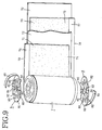
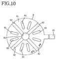
- FIGS. 9 and 10 show a current collector plate 8 which comprises a circular flat platelike body 81 integrally formed with a plurality of circular-arc protrusions 82 extending radially thereof and projecting toward the rolled-up electrode unit 7.
- the collector body 81 has a center hole 84 and a plurality of liquid inlets 83 around the center hole 84.
- the aforementioned lead portion 85 which is in the form of a strip, is integral with an end portion of the collector body 81.
- Each protrusion 82 of the collector plate 8 is in the form of a circular arc, i.e., semicircular, in section orthgonal to a radial line of the collector body 81 as seen in FIG. 11.
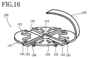
- FIGS. 16 and 17 show a current collector plate 100 having a different construction.
- the collector plate 100 comprises a circular flat platelike body 101 integrally formed with a plurality of trapezoidal protrusions 102 extending radially thereof and projecting toward the rolled-up electrode unit 7.
- the collector body 101 has a center hole 104 and a plurality of liquid inlets 103 around the center hole 104.
- a lead portion 105 in the form of a strip is integral with an end portion of the collector body 101.
- the collector body 101 is further provided along its outer periphery with a current collector pressing portion 106 projecting downward and positioned close to each of opposite sides of the protrusion 102 for pressing the outer end of the current collector 77 of the electrode unit 7 inwardly of the unit 7.
- the current collector pressing portion 106 is formed by cutting and bending an outer peripheral portion of the collector body 101 to the shape of a strip measuring 2 mm in width X and 5 mm in length Y as shown in FIG. 17.
- the collector plate 100 is pressed against the end of the rolled-up electrode unit 7, whereby the corresponding end of the current collector 77 is deflected inwardly of the unit 7 by being pressed by the current collector pressing portion 106. This shifts the position of contact between the current collector end and the protrusion 102 of the collector plate 100 also inwardly of the electrode unit 7.
- the collector plate 100 is welded to the end of the electrode unit 7 with a laser beam, the laser beam is moved, for example, from the inner peripheral side of the plate 100 toward the outer periphery thereof along the protrusion 102 of the plate 100 as indicated in two-dot chain lines in FIG.
- the spot 107a as positioned most radially outwardly of the collector plate 100 can be confined to an area slightly inwardly of the radial outer end 102a of the protrusion 102 of the plate 100 due to the deflection of the end portion of the current collector 77.
- the outermost spot 107a is positioned at the radial outer end 102a of the collector plate protrusion 102.
- the laser beam is then partly projected outwardly of the outer periphery of the collector plate 100, possibly melting the outermost portion of the current collector 77 or separator 72 of the electrode unit 7.
- the outermost spot 107a will not be positioned outside the outer periphery of the collector plate 100. This eliminates the likelihood of the laser beam melting the current collector 77 or separator 72, consequently assuring that the collector plate 100 will be reliably welded even to the radially outermost portion of the current collector 77 of the unit 7 like the other portions thereof and permitting the plate 100 to be joined to the electrode unit 7 over an increased area to achieve an improved current collecting efficiency.
- Invention cells A, B, C, D, E and comparative cells F, G, H, I were fabricated in the following manner.
- a rolled-up electrode unit 7 was prepared by arranging in superposed layers a positive electrode 71 obtained by coating an aluminum current collector 75 having a thickness of 20 ⁇ m with a positive electrode active material 74 comprising LiCo 2 , a negative electrode 73 obtained by coating a copper current collector 77 having a thickness of 20 ⁇ m with a negative electrode active material 76 of graphite and a separator 72 in the form of an ion-permeable finely porous membrane of polypropylene, and rolling up these components into a spiral form.
- the positive electrode 71 and the negative electrode 73 each had an uncoated portion of predetermined width at a widthwise end thereof.
- a current collector plate 8 of aluminum was prepared which comprised a flat platelike body 81 having a thickness of 1 mm and a plurality of circular-arc radial protrusions 82 and formed with a plurality of liquid inlets 83 in an opening ratio of 50%.
- the collector plate 8 was fitted over the positive electrode current collector edge 78 of the electrode unit 7 and pressed thereagainst with a jig from above.
- the circular-arc protrusions 82 of the collector plate 8 were 1 mm in wall thickness T and 1.2 mm in inside radius R.
- a current collecting structure for the positive electrode was then made by welding the base end of an aluminum lead piece, 1 mm in thickness, to the surface of the collector plate 8 with a laser beam, and similarly welding the outer end of the lead piece to the rear face of an aluminum electrode terminal.
- a negative electrode current collecting structure was prepared in the same manner as above except that the electrode terminal, current collector plate and lead piece used were made from nickel.
- the rolled-up electrode unit 7 was thereafter encased in a cylinder 15, and a lid 16 having an electrode terminal assembly 110 mounted thereon is fixedly welded to each open end of the cylinder 15.
- An ester-type organic electrolyte containing 1 mole/liter of LiPF 6 serving as the electrolytic substance to be supported was subsequently placed into the cylinder to fabricate a cell having a power capacity of 180-Wh class as a component cell.
- Invention cells B were assembled in the same manner as invention cell A with the exception of using current collector plates 120 having protrusions 121 which were trapezoidal in section as shown in FIG. 15. Seven kinds of cells B, i.e., cells B1 to B7, were prepared which were 10%, 15%, 30%, 50%, 70%, 90% and 93%, respectively, in the opening ratio given by liquid inlets.
- the furrow forming each trapezoidal protrusion 121 was 1.2 mm in depth H and 1.6 mm in furrow width B at the furrow bottom.
- Invention cell C was assembled in the same manner as invention cells B except that the flat collector body was integrally formed with a lead portion having the same thickness as the collector body.
- the opening ratio given by the liquid inlets was 50%.
- the outer end of the lead portion was welded to the rear face of the electrode terminal with a laser beam.
- invention cells D i.e., 23 kinds of invention cells D1 to D23, were assembled basically in the same manner as invention cell C except that the cells were different in the shape and size of the furrow forming the trapezoidal protrusion as will be described below.
- the area of openings was 50% of the overall area.
- Invention cells D1 to D5 were 0.6 times, 0.8 times, 10 times, 1.2 times and 1.6 times the laser spot diameter, respectively, in the furrow width B at the furrow bottom.
- Invention cells D6 to D14 were 0.3 mm, 0.5 mm, 0.8 mm, 1.2 mm, 1.6 mm, 2.0 mm, 2.5 mm, 3.0 mm and 3.5 mm, respectively, in furrow depth H.
- Further invention cells D15 to D23 were 0.05 mm, 0.10 mm, 0.20 mm, 0.50 mm, 1.00 mm, 1.50 mm, 2.00 mm, 2.50 mm and 3.00 mm, respectively, in the thickness T of the current collector plate.
- Invention cells D1 to D5 were 1 mm in the thickness T of the current collector plate, 1.2 mm in the furrow depth H of the protrusion and 1 mm in the wall thickness S of the protrusion.
- Invention cells D6 to D14 were 1 mm in the thickness T of the current collector plate, 1.6 mm in the furrow width B of the protrusion and 1 mm in the wall thickness S of the protrusion.
- Invention cells D15 to D23 bad a protrusion wall thickness S which was equal to the thickness T of the current collector plate, and were 1.6 mm in the furrow width B of the protrusion and 1.2 mm in the furrow depth H of the protrusion.
- Invention cell E was assembled in the same manner as invention cell D except that the cell had current collector plates 120 as shown in FIG. 15 and measuring 1 mm in thickness T and 0.5 mm in the wall thickness S of the trapezoidal protrusion 121.
- the opening ratio given by the liquid inlets was 50%.
- the furrow depth H of the protrusion was 1.2 mm and the furrow width B at the furrow bottom of the protrusion was 1.6 mm.
- current collector plates 92 were prepared which comprised a flat platelike body 93 having a thickness of 1 mm and four bent portions 94 as shown in FIG. 24. Each collector plate 92 was placed at the current collector edge 78 of a rolled-up electrode unit 7 and joined thereto by spot welding using two electrode rods. A lead was joined at opposite ends thereof to the collector plate 92 and an electrode terminal by spot welding to provide a current collecting structure, and the components were assembled into a cell in the same manner as above.
- current collector members 95 were prepared which had a plurality of slits 96 as shown in FIG. 25.
- the current collector edge 78 of a rolled-up electrode unit 7 was inserted into the slits 96 of each collector member 95, which was joined to the current collector edge 78 by laser welding.
- a lead was joined at opposite ends thereof to the collector member 95 and an electrode terminal by laser welding to provide a current collecting structure, and the components were assembled into a cell in the same manner as above.
- a current collector plate 9 of aluminum having a thickness of 1 mm and protrusions 91 V-shaped in section and having an end angle of 45° was pressed against the edge 78 of a positive electrode current collector of aluminum having a thickness of 20 ⁇ m and included in a rolled-up electrode unit as shown in FIG. 14.
- Each V-shaped protrusion 91 was irradiated with a laser beam in this state for laser welding.
- An aluminum lead, 1 mm in thickness, was thereafter joined at opposite ends thereof to the collector plate 9 and an electrode terminal to provide a current collecting structure for the positive electrode.
- a negative electrode current collecting structure was prepared in the same manner as the structure for the positive electrode except that the electrode terminal, lead and current collector plate were made from nickel.
- Invention cells I were assembled in the same manner as invention cell D with the exception of using current collector plates 100 having protrusion 102 of trapezoidal section as seen in FIGS. 16 and 17.
- Each plate 100 was 1 mm in thickness T, 1.2 mm in the furrow depth H of the protrusion, 0.5 mm in the wall thickness S of the protrusion, 1.6 mm in the furrow width B of the protrusion, 50% in the opening ratio given by the liquid inlets 103, 2 mm in the width X of the current collector pressing portion 106 and 5 mm in length Y thereof.
- invention cells I1 to I6 were fabricated which were 15°, 30°, 40°, 45°, 60° and 80°, respectively, in the angle ⁇ made by the current collector pressing face of the current collector pressing portion 106 and the surface of the flat platelike body 101 of the collector plate 100 as shown in FIG. 19.
- Tables 10 to 12 collectively show the constructions of the cells and the measurement of powers.
- invention cell A and comparative cells F, G, H were charged at 0.125 C to 4.1 V, then discharged at 0.5 C to a depth of discharge of 40% and thereafter checked for power characteristics at a current value of 4 C for a discharge period of 10 seconds.
- Table 13 shows the result.
- the power density was determined by calculating the power value based on the voltage-current characteristics under the above conditions and dividing the result by the weight of the cell.
- the conditions for laser welding for the fabrication of invention cell A were: laser power of 400 W, pulse frequency of 15 Hz and laser beam spot diameter D of 1 mm.
- POWER DENSITY(W/kg) CELL A (INVENTION CELL) 590 CELL F (COMP. CELL) 540 CELL G (COMP. CELL) 560 CELL H (COMP. CELL) 570
- Comparative cell G had a higher power than comparative cell F but is inferior to invention cell A in power. This is attributable to the feature of invention cell A wherein the current was collected by four radial circular-arc protrusions 82 and which therefore exhibited a diminished current distribution, whereas comparative cell G had a structure for collecting the current from a portion, in circumferential direction, of the electrode unit and therefore exhibited a greater current distribution than invention cell A during high-rate discharge although the area of contact between the current collector and the current collector member was greater than in invention cell A.
- comparative cell G requires work for inserting the current collector into the slits of the current collector member, hence a complex procedure, whereas in the case of invention cell A, the current collector plate needs only to be pressed against the current collector edge to ensure a simplified welding step.
- comparative cell H is higher than comparative cell G but lower than invention cell A.
- comparative cell H like invention cell A, is adapted to collect the current from the entire current collector of the rolled-up electrode unit, the protrusion 91 is V-shaped in section as seen in FIG. 14, so that the width W' of the junction of the protrusion 91 and the current collector edge 78 is smaller than the width W of the junction of the circular-arc protrusion 82 and the current collector edge 78 notwithstanding that the protrusion 82 is the same as the protrusion 91 in depth and width. The difference in power is thought attributable to the smaller width W' which resulted in a smaller contact area.
- Invention cell A and invention cell B4 were checked for the comparison of power characteristics in the case where the current collector plates thereof were welded under the same conditions, i.e., 400 W in laser power, and 15 Hz in pulse frequency. Table 14 shows the result.
- the cells were charged at 0.125 C to 4.1 V, then discharged at 0.5 C to a depth of discharge of 40% and thereafter checked for power at a current value of 4 C for a discharge period of 10 seconds.
- POWER DENSITY W/kg
- invention cell B4 is superior to invention cell A in power characteristics, presumably because the trapezoidal protrusion 102 of cell B4 is greater than the circular-arc protrusion 82 of cell A in the area of contact of the protrusion with the current collector edge 78, and further because the portion of the cell B4 to be irradiated with the laser beam is flat over a wider area, permitting the laser beam energy to act more effectively to produce a weld over a sufficient junction area.
- invention cells B1 to B7 were tested for impregnation with the electrolyte in the following manner and checked for the time taken for the rolled-up electrode unit to be impregnated with the electrolyte.
- the rolled-up electrode unit having the current collector plates attached thereto was checked for weight and then placed into a container of SUS within a dry box having an argon gas atmosphere.
- the container was filled with the electrolyte and subjected to a pressure of 5 kg/cm 2 .
- the electrode unit was withdrawn from the container every 10 minutes and checked for weight to measure the time taken for a predetermined amount of electrolyte to impregnate the electrode unit.
- Table 15 shows the result.
- the opening ratio of the current collector plate given by the liquid inlets is preferably in the range of 15% to 90%.
- Invention cell B4 and invention cell C were charged at 0.125 C to 4.1 V, then discharged at 0.5 C to a depth of discharge of 40% and thereafter checked for power at a current value of 4 C for a discharge period of 10 seconds.
- Table 17 shows the result.
- Invention cells D1 to D5 were checked for the comparison of power characteristics in the case where the current collector plates thereof were welded under the same conditions, i.e., 400 W in laser power, and 15 Hz in pulse frequency. Table 18 shows the result.
- the laser beam was 1 mm in spot diameter.
- the cells were charged at 0.125 C to 4.1 V, then discharged at 0.5 C to a depth of discharge of 40% and checked for power at a current value of 4 C for a discharge period of 10 seconds.
- CELL D1 D2 D3 D4 D5 FURROW WIDTH/SPOT DIAM. 0.6 0.8 1.0 1.2 1.6 POWER DENSITY(W/kg) 600 606 608 610 611
- the furrow width of the collector plate protrusion be at least 0.8 times the spot diameter D of the laser beam.
- Invention cells D6 to D14 were checked for the comparison of power characteristics in the case where the current collector plates thereof were welded under the same conditions, i.e., 400 W in laser power, and 15 Hz in pulse frequency. Table 19 shows the result.
- the laser beam was 1 mm in spot diameter.
- the cells were charged at 0.125 C to 4.1 V, then discharged at 0.5 C to a depth of discharge of 40% and checked for power at a current value of 4 C for a discharge period of 10 seconds.
- the power characteristics remain unaltered even if the furrow depth of the protrusion is greater than 3 mm presumably because even if the furrow depth is greater than 3 mm, the effect to increase the area of contact remains unchanged since the variations in the position of the current collector edge of the rolled-up electrode unit are usually up to 2 mm.
- the collector plate protrusion is excessively large, the collector plate occupies a greater volume in the interior of the battery can to diminish the volumetric energy density of the cell.
- the furrow depth of the collector plate protrusion be in the range of 0.5 mm to 3 mm.
- Invention cells D15 to D23 were checked for power characteristics in the case where the current collector plates thereof were welded under the same conditions, i.e., 400 W in laser power, and 15 Hz in pulse frequency. Table 20 shows the result.
- the cells were charged at 0.125 C to 4.1 V, then discharged at 0.5 C to a depth of discharge of 40% and checked for power at a current value of 4 C for a discharge period of 10 seconds.
- CELL D15 D16 D17 D18 D19 D20 D21 D22 D23 THICKNESS (mm) 0.05 0.1 0.2 0.5 1.0 1.5 2.0 2.5 3.0 POWER DENSITY (W/kg) 590 597 602 608 611 614 616 616 616 616 616 616
- the result of Table 20 reveals that when the thickness of the current collector plate is smaller than 0.1 mm, the power greatly reduces. Presumably, the reason is that when having a thickness smaller than 0.1 mm, the collector plate has increased electric resistance to exhibit an impaired current collecting efficiency. However, even if the thickness of the collector plate is made greater than 2 mm, the effect to improve the current collecting efficiency levels off, while the lead portion projecting from the collector plate then becomes less amenable to working such as bending.
- the thickness of the current collector plate be in the range of 0.1 mm to 2 mm.
- Invention cells D5 and E were checked for power characteristics in the case where the current collector plates thereof were welded under the same conditions, i.e., 350 W in laser power, and 15 Hz in pulse frequency. Table 21 shows the result. For an power characteristics test, the cells were charged at 0.125 C to 4.1 V, then discharged at 0.5 C to a depth of discharge of 40% and checked for power at a current value of 4 C for a discharge period of 10 seconds.
- the current collector plates 8 of the cells were 1 mm in the thickness of the flat platelike body 81, 1 mm in wall thickness of the circular-arc protrusion 82 and 1.2 mm in the furrow depth of the protrusion 82.
- the current collector plates 8 of the cells were welded under the same conditions, i.e., 400 W in laser power, and 15 Hz in pulse frequency.
- the result of Table 22 indicates that excellent power characteristics are available when the radius R of the circular-arc protrusion 82 of the current collector plate 8 is at least 0.4 times the spot diameter D of the laser beam.
- the reason is that if the radius R of the protrusion 82 is smaller than 0.4 times the laser beam spot diameter D, the laser beam is projected onto opposite ends of the protrusion 82, i.e., regions not to be welded to the current collector edge 78, whereby the energy of the laser beam to be used effectively for welding is diminished, failing to fully melt the portions to be welded and consequently reducing the area of contact between the collector plate and the current collector edge to result in an impaired current collecting efficiency.
- the radius R of circular-arc protrusion 82 of the current collector plate 8 be at least 0.4 times the spot diameter D of the laser beam.
- Invention cells I1 to I6 and invention cell E were tested for power characteristics.
- the current collector plates 100 of the cells were welded under the same conditions, i.e., 400 W in laser power, and 15 Hz in pulse frequency.
- the cells were charged at 0.125 C to 4.1 V, then discharged at 0.5 C to a depth of discharge of 40% and checked for power characteristics at a current value of 4 C for a discharge period of 10 seconds.
- Table 23 shows the result.
- Table 23 indicates that invention cells I1 to I6 wherein the current collector pressing portions 106 are formed exhibit a higher power density than invention cell E (wherein the angle ⁇ is 0°).
- the reason is that the current collector pressing portion 106 deflects the end portion of the current collector 77 inwardly of the electrode unit 7 by pressing the end portion, whereby the position of contact of the collector plate protrusion 102 with the current collector is shifted also inwardly of the unit 7, consequently permitting the current collector portion positioned at the outer periphery of the electrode unit 7 to be welded like other current collector portions and ensuring a large junction area to achieve an improved current collecting efficiency.
- the angle ⁇ is at least 30° to not greater than 45°. This is because if the angle ⁇ is smaller than 30°, the end portion of the current collector 77 of the rolled-up electrode 7 will not be fully deflected inward, and further because if the angle ⁇ is greater than 45°, the current collector pressing portion 106 will be forced into the end portion of the rolled-up electrode unit 7, failing to fully deflect the end portion of the current collector 77 inward. Resulting in either case is only a small inward shift in the position of contact between the current collector end portion of the electrode unit 7 and the collector plate protrusion 102, so that a sufficiently large area of junction is not available. Accordingly, the angle ⁇ to be made by the current collector pressing face of the current collector pressing portion 106 and the surface of flat platelike body 101 of the current collector plate is preferably at least 30° to not greater than 45°.
- the cells of the present invention are not limited to the foregoing embodiments in construction but can be modified variously within the technical scope set forth in the appended claims.
- ferritic stainless steel or martensitic stainless steel is also usable as the material for the metal layer of the negative electrode current collector plate 3.
- the laser beam is used for welding the current collector plate according to the embodiments described, this method of welding is not limitative but an electron beam is also usable for welding.
- the present invention can be embodied not only as lithium ion secondary cells but as a wide variety of nonaqueous electrolyte secondary cells.
Landscapes
- Chemical & Material Sciences (AREA)
- Chemical Kinetics & Catalysis (AREA)
- Electrochemistry (AREA)
- General Chemical & Material Sciences (AREA)
- Engineering & Computer Science (AREA)
- Manufacturing & Machinery (AREA)
- Materials Engineering (AREA)
- Connection Of Batteries Or Terminals (AREA)
- Secondary Cells (AREA)
- Cell Electrode Carriers And Collectors (AREA)
Applications Claiming Priority (4)
| Application Number | Priority Date | Filing Date | Title |
|---|---|---|---|
| JP22649099 | 1999-08-10 | ||
| JP22649099 | 1999-08-10 | ||
| JP26771299 | 1999-09-21 | ||
| JP26771299 | 1999-09-21 |
Publications (2)
| Publication Number | Publication Date |
|---|---|
| EP1076371A1 true EP1076371A1 (fr) | 2001-02-14 |
| EP1076371B1 EP1076371B1 (fr) | 2011-10-12 |
Family
ID=26527188
Family Applications (1)
| Application Number | Title | Priority Date | Filing Date |
|---|---|---|---|
| EP00117158A Expired - Lifetime EP1076371B1 (fr) | 1999-08-10 | 2000-08-10 | Cellule électrolytique secondaire non-aqueuse et son procédé de fabrication |
Country Status (4)
| Country | Link |
|---|---|
| US (5) | US6692863B1 (fr) |
| EP (1) | EP1076371B1 (fr) |
| KR (2) | KR100675700B1 (fr) |
| CN (2) | CN1172400C (fr) |
Cited By (20)
| Publication number | Priority date | Publication date | Assignee | Title |
|---|---|---|---|---|
| FR2824667A1 (fr) * | 2001-05-14 | 2002-11-15 | Cit Alcatel | Connectique interne pour generateur electrochimique de forte puissance |
| EP1087451A3 (fr) * | 1999-09-21 | 2003-07-23 | Matsushita Electric Industrial Co., Ltd. | Unité de plaques d'électrodes pour batterie rechargeable et son procédé de fabrication |
| WO2003077332A1 (fr) * | 2002-03-13 | 2003-09-18 | Sanyo Electric Co., Ltd. | Batterie auxiliaire |
| EP1255310A3 (fr) * | 2001-05-02 | 2004-11-24 | Ngk Insulators, Ltd. | Pile secondaire au lithium |
| EP1291939A3 (fr) * | 2001-09-08 | 2005-06-22 | VARTA Automotive Systems GmbH | Elément galvanique comportant assemblage d'électrodes enroulées |
| WO2006042416A1 (fr) * | 2004-10-21 | 2006-04-27 | Avestor Limited Patnership | Cellule electrochimique en couche mince pour batteries polymeres au lithium et procede pour la fabriquer |
| EP1983595A1 (fr) * | 2007-04-11 | 2008-10-22 | Saft Groupe Sa | Système de connexion pour cellule électrochimique |
| EP1995805A1 (fr) | 2007-05-22 | 2008-11-26 | Hitachi Vehicle Energy, Ltd. | Batterie secondaire au lithium-ion |
| EP2003716A1 (fr) * | 2007-06-11 | 2008-12-17 | Hitachi Vehicle Energy, Ltd. | Batterie secondaire au lithium-ion |
| EP2061106A1 (fr) | 2007-11-13 | 2009-05-20 | Hitachi Vehicle Energy, Ltd. | Accumulateur à lithium |
| US7781095B2 (en) | 2004-06-23 | 2010-08-24 | Samsung Sdi Co., Ltd. | Rechargeable battery having current collecting plates coupled with uncoated regions of electrodes |
| US7867644B2 (en) | 2007-01-31 | 2011-01-11 | Hitachi Vehicle Energy, Ltd. | Secondary battery and secondary battery manufacturing method |
| US8021775B2 (en) * | 2001-07-13 | 2011-09-20 | Inventek Corporation | Cell structure for electrochemical devices and method of making same |
| FR2974451A1 (fr) * | 2011-04-20 | 2012-10-26 | Accumulateurs Fixes | Connexion electrique pour accumulateur de courant |
| EP2717373A4 (fr) * | 2011-05-25 | 2014-12-03 | Shin Kobe Electric Machinery | Unité de regroupement de plaques d'électrodes pour accumulateur et procédé de fabrication de celle-ci |
| FR3030118A1 (fr) * | 2014-12-15 | 2016-06-17 | Saft Groupe Sa | Procede de connexion dans un accumulateur et accumulateur ainsi connecte |
| CN110364678A (zh) * | 2018-04-10 | 2019-10-22 | 通用汽车环球科技运作有限责任公司 | 制造锂金属负极的方法 |
| CN113853702A (zh) * | 2019-05-22 | 2021-12-28 | 三星Sdi株式会社 | 二次电池 |
| EP4485592A1 (fr) * | 2023-06-29 | 2025-01-01 | Volvo Car Corporation | Élément de batterie, véhicule et procédé de fabrication d'un élément de batterie |
| EP4496082A1 (fr) * | 2023-07-18 | 2025-01-22 | VARTA Microbattery GmbH | Élément accumulateur d'énergie électrochimique doté d'une partie de tôle de contact et son procédé de fabrication |
Families Citing this family (129)
| Publication number | Priority date | Publication date | Assignee | Title |
|---|---|---|---|---|
| KR100675700B1 (ko) * | 1999-08-10 | 2007-02-01 | 산요덴키가부시키가이샤 | 비수 전해액 이차 전지 및 그 제조 방법 |
| JP2002025559A (ja) * | 2000-07-03 | 2002-01-25 | Sony Corp | 電 池 |
| US7387851B2 (en) | 2001-07-27 | 2008-06-17 | A123 Systems, Inc. | Self-organizing battery structure with electrode particles that exert a repelling force on the opposite electrode |
| JP2004525481A (ja) | 2000-10-20 | 2004-08-19 | マサチューセッツ・インスティチュート・オブ・テクノロジー | 網状で、制御された有孔率の電池構造 |
| CN1233053C (zh) * | 2000-12-22 | 2005-12-21 | 吴崇安 | 一种用于棱柱形电池的电极组件 |
| DE10108695A1 (de) * | 2001-02-23 | 2002-09-05 | Varta Geraetebatterie Gmbh | Galvanisches Element mit mindestens einer lithiuminterkalierenden Elektrode |
| US7195840B2 (en) * | 2001-07-13 | 2007-03-27 | Kaun Thomas D | Cell structure for electrochemical devices and method of making same |
| JP4619000B2 (ja) | 2001-07-27 | 2011-01-26 | マサチューセッツ インスティテュート オブ テクノロジー | 電池構造、自己組織化構造、及び関連方法 |
| CN1320684C (zh) * | 2002-03-08 | 2007-06-06 | 居永明 | 可反复充放电的锂离子动力电池及其制造方法 |
| US7763382B2 (en) * | 2002-07-26 | 2010-07-27 | A123 Systems, Inc. | Bipolar articles and related methods |
| FR2846386B1 (fr) * | 2002-10-28 | 2006-03-03 | Poclain Hydraulics Ind | Dispositif d'echange et/ou de balayage pour un circuit comprenant au moins un moteur hydraulique |
| JP4184927B2 (ja) * | 2002-12-27 | 2008-11-19 | 三星エスディアイ株式会社 | 2次電池及びその製造方法 |
| JP2004303500A (ja) * | 2003-03-31 | 2004-10-28 | Sanyo Electric Co Ltd | 角形電池 |
| KR100563055B1 (ko) * | 2003-08-19 | 2006-03-24 | 삼성에스디아이 주식회사 | 권취형 전극 조립체 및 이를 구비한 이차 전지 |
| KR100516772B1 (ko) * | 2003-08-22 | 2005-09-22 | 삼성에스디아이 주식회사 | 전극탭을 캔의 단변부에 위치시킨 이차전지 |
| US7601460B2 (en) * | 2003-11-28 | 2009-10-13 | Panasonic Corporation | Prismatic battery and manufacturing method thereof |
| WO2005061171A1 (fr) * | 2003-12-24 | 2005-07-07 | Maxwell Technologies Sa | Procede de brasage permettant d'obtenir une connexion mecanique et electrique entre deux pieces |
| KR100658614B1 (ko) * | 2004-01-16 | 2006-12-15 | 삼성에스디아이 주식회사 | 이차 전지 |
| KR100536253B1 (ko) * | 2004-03-24 | 2005-12-12 | 삼성에스디아이 주식회사 | 이차 전지 |
| US8734983B2 (en) * | 2004-04-14 | 2014-05-27 | Inventek Corporation | Housing for electrochemical devices |
| KR100589347B1 (ko) * | 2004-04-27 | 2006-06-14 | 삼성에스디아이 주식회사 | 이차 전지 |
| KR100599598B1 (ko) * | 2004-05-04 | 2006-07-13 | 삼성에스디아이 주식회사 | 이차 전지와 이에 사용되는 전극 조립체 및 집전판 |
| KR100599792B1 (ko) * | 2004-05-19 | 2006-07-13 | 삼성에스디아이 주식회사 | 이차 전지와 이에 사용되는 전극 조립체 및 집전판 |
| KR100599793B1 (ko) * | 2004-05-19 | 2006-07-13 | 삼성에스디아이 주식회사 | 이차 전지와 이에 사용되는 전극 조립체 |
| KR100590006B1 (ko) * | 2004-06-23 | 2006-06-14 | 삼성에스디아이 주식회사 | 이차 전지와 이에 사용되는 전극 조립체 |
| KR100599713B1 (ko) * | 2004-06-25 | 2006-07-12 | 삼성에스디아이 주식회사 | 이차 전지와 이에 사용되는 전극 조립체 |
| KR100599710B1 (ko) * | 2004-07-28 | 2006-07-12 | 삼성에스디아이 주식회사 | 이차 전지와 이에 사용되는 전극 조립체 및 이차 전지제조 방법 |
| KR100599802B1 (ko) * | 2004-09-21 | 2006-07-12 | 삼성에스디아이 주식회사 | 이차 전지와 이에 사용되는 전극 조립체 및 집전판 |
| KR100599803B1 (ko) * | 2004-09-24 | 2006-07-12 | 삼성에스디아이 주식회사 | 이차 전지와 이에 사용되는 전극 조립체 및 집전판 |
| JP4977951B2 (ja) * | 2004-11-30 | 2012-07-18 | 株式会社Gsユアサ | 密閉形電池とその製造方法及び密閉形電池の複数個で構成した組電池 |
| JP4817871B2 (ja) * | 2005-03-30 | 2011-11-16 | 三洋電機株式会社 | 電池 |
| US20060263686A1 (en) * | 2005-05-19 | 2006-11-23 | Medtronic, Inc. | Lithium battery manufacturing method |
| JP5051410B2 (ja) * | 2005-05-30 | 2012-10-17 | 株式会社Gsユアサ | 密閉形電池用リード、そのリードを用いた密閉形電池及びその電池の製造方法 |
| US7998500B2 (en) * | 2005-08-04 | 2011-08-16 | Vertical Pharmaceuticals, Inc. | Nutritional supplement for women |
| JP2007115584A (ja) * | 2005-10-21 | 2007-05-10 | Panasonic Ev Energy Co Ltd | 二次電池とその製造方法及び二次電池用集電板 |
| WO2007086218A1 (fr) * | 2006-01-24 | 2007-08-02 | Murata Manufacturing Co., Ltd. | Pile à microcircuit |
| US20110016706A1 (en) * | 2006-04-19 | 2011-01-27 | Exa Energy Technology Co., Ltd. | Rechargeable battery fabrication method |
| TW200742150A (en) * | 2006-04-19 | 2007-11-01 | Exa Energy Technology Co Ltd | Method for producing secondary battery |
| KR20090012262A (ko) * | 2006-05-09 | 2009-02-02 | 발렌스 테크놀로지, 인코포레이티드 | 증가된 집전 효율을 갖는 2차 전기화학 전지 |
| US20080020258A1 (en) * | 2006-07-24 | 2008-01-24 | Tsang-Ming Chang | Current collection board for fuel cell |
| KR100786871B1 (ko) * | 2006-07-27 | 2007-12-20 | 삼성에스디아이 주식회사 | 이차 전지 |
| US20080102346A1 (en) * | 2006-10-27 | 2008-05-01 | Kenneth Smith | Current collector plate |
| US8202642B2 (en) * | 2006-11-15 | 2012-06-19 | Panasonic Corporation | Current collector for non-aqueous secondary battery, electrode plate for non-aqueous secondary battery using the same, and non-aqueous secondary battery |
| US9289266B2 (en) | 2006-12-01 | 2016-03-22 | Boston Scientific Scimed, Inc. | On-axis drive systems and methods |
| WO2008086417A2 (fr) * | 2007-01-09 | 2008-07-17 | Johnson-Controls--Saft Advanced Power Solutions Llc | Élément de batterie |
| JP4894543B2 (ja) * | 2007-02-08 | 2012-03-14 | パナソニック株式会社 | キャパシタ |
| JP4296205B2 (ja) * | 2007-03-29 | 2009-07-15 | 株式会社東芝 | 非水電解質電池、電池パック及び自動車 |
| KR100914108B1 (ko) * | 2007-05-03 | 2009-08-27 | 삼성에스디아이 주식회사 | 전극 조립체 및 이를 구비하는 이차 전지 |
| EP4233962B1 (fr) | 2007-05-18 | 2025-11-05 | Boston Scientific Scimed, Inc. | Systèmes d'entraînement médicaux |
| KR100985606B1 (ko) * | 2007-05-24 | 2010-10-05 | 닛산 지도우샤 가부시키가이샤 | 비수용매 2차 전지용 집전체 및 이것을 이용한 전극 및전지 |
| US20090202903A1 (en) | 2007-05-25 | 2009-08-13 | Massachusetts Institute Of Technology | Batteries and electrodes for use thereof |
| JP5219422B2 (ja) * | 2007-07-31 | 2013-06-26 | 三洋電機株式会社 | 非水電解質二次電池 |
| KR100922352B1 (ko) | 2007-10-02 | 2009-10-21 | 삼성에스디아이 주식회사 | 이차 전지 |
| TW200925328A (en) * | 2007-10-29 | 2009-06-16 | Bhp Billiton Aluminium Technologies Ltd | Composite collector bar |
| KR100943575B1 (ko) * | 2007-10-29 | 2010-02-23 | 삼성에스디아이 주식회사 | 이차 전지 |
| JP2009110751A (ja) * | 2007-10-29 | 2009-05-21 | Panasonic Corp | 二次電池 |
| CN101652886B (zh) * | 2007-10-30 | 2012-06-13 | 松下电器产业株式会社 | 电池用集电体及其制造方法以及非水系二次电池 |
| JP5137530B2 (ja) * | 2007-11-05 | 2013-02-06 | パナソニック株式会社 | 二次電池及びその製造方法 |
| FR2928035B1 (fr) * | 2008-02-22 | 2011-08-19 | Saft Groupe Sa | Connexion electrique pour accumulateur de courant. |
| JP5169395B2 (ja) * | 2008-04-07 | 2013-03-27 | トヨタ自動車株式会社 | 塗布装置及び塗布方法 |
| US20100020471A1 (en) * | 2008-07-24 | 2010-01-28 | Adrian Schneuwly | Electrode Device |
| FR2935544B1 (fr) * | 2008-08-29 | 2010-08-27 | Saft Groupe Sa | Collecteur de courant pour anode de generateur electrochimique primaire au lithium |
| JP5225002B2 (ja) * | 2008-09-30 | 2013-07-03 | 株式会社東芝 | 二次電池 |
| KR101108118B1 (ko) * | 2008-11-27 | 2012-01-31 | 주식회사 엠플러스 | 이차전지 제조방법 및 이차전지 |
| CN102334216B (zh) * | 2008-12-19 | 2017-06-16 | 株式会社Lg化学 | 高功率锂二次电池 |
| KR101072956B1 (ko) * | 2009-03-30 | 2011-10-12 | 에스비리모티브 주식회사 | 이차전지 |
| KR101306410B1 (ko) | 2009-08-05 | 2013-09-09 | 파나소닉 주식회사 | 밀폐형 전지 및 그 제조방법 |
| US8574752B2 (en) * | 2009-10-29 | 2013-11-05 | Samsung Sdi Co., Ltd. | Electrode assembly and rechargeable battery using the same |
| JP5658450B2 (ja) * | 2009-11-12 | 2015-01-28 | 川崎重工業株式会社 | 電池システム |
| CN102237199A (zh) * | 2010-04-21 | 2011-11-09 | 财团法人金属工业研究发展中心 | 电储存装置、电储存装置的电极组及其制造方法 |
| CN102356496B (zh) * | 2010-05-21 | 2014-07-23 | 丰田自动车株式会社 | 二次电池 |
| JP5306418B2 (ja) * | 2010-07-09 | 2013-10-02 | 日新製鋼株式会社 | 銅被覆鋼箔、負極用電極及び電池 |
| JP5189626B2 (ja) * | 2010-08-31 | 2013-04-24 | トヨタ自動車株式会社 | 電池の製造方法、電池、溶接前正極板の製造方法、及び溶接前正極板 |
| US9065093B2 (en) | 2011-04-07 | 2015-06-23 | Massachusetts Institute Of Technology | Controlled porosity in electrodes |
| WO2013066683A2 (fr) | 2011-11-03 | 2013-05-10 | Johnson Controls Technology Llc | Cellule aux ions-lithium prismatique ayant un récipient rigide de polarité positive |
| CN110224087A (zh) * | 2011-11-03 | 2019-09-10 | Cps科技控股有限公司 | 具有正极性刚性容器的棱柱形锂离子电池单元 |
| DE102012213420A1 (de) * | 2012-07-31 | 2014-02-27 | Robert Bosch Gmbh | Verfahren zum Herstellen einer Anschlusskontaktierung für eine Elektrode eines elektrochemischen Speichers, Verfahren zum Herstellen eines elektrochemischen Speichers und elektrochemischer Speicher |
| US10003067B2 (en) * | 2012-09-12 | 2018-06-19 | Gs Yuasa International Ltd. | Electric storage device and method for producing electric storage device |
| KR101726909B1 (ko) | 2013-10-23 | 2017-04-13 | 삼성에스디아이 주식회사 | 광흡수 부재를 갖는 이차 전지 |
| DE102014200011A1 (de) * | 2014-01-03 | 2015-07-09 | Robert Bosch Gmbh | Elektroden für Batteriezellen |
| CN105849938A (zh) * | 2014-01-31 | 2016-08-10 | 弗拉迪米尔·列奥尼多维奇·杜曼诺夫 | 电化学设备 |
| JP6201795B2 (ja) * | 2014-02-10 | 2017-09-27 | トヨタ自動車株式会社 | 蓄電装置の製造方法 |
| US10675819B2 (en) | 2014-10-03 | 2020-06-09 | Massachusetts Institute Of Technology | Magnetic field alignment of emulsions to produce porous articles |
| US10569480B2 (en) | 2014-10-03 | 2020-02-25 | Massachusetts Institute Of Technology | Pore orientation using magnetic fields |
| KR102382052B1 (ko) * | 2015-03-02 | 2022-04-01 | 삼성에스디아이 주식회사 | 이차 전지 모듈 |
| JP6287946B2 (ja) * | 2015-05-08 | 2018-03-07 | トヨタ自動車株式会社 | 電池用積層体の製造方法 |
| CN108701801A (zh) * | 2015-12-14 | 2018-10-23 | 奥克海德莱克斯控股有限公司 | 能够在高电压下工作的电化学电池及其组件 |
| CN107949947B (zh) * | 2016-02-26 | 2021-03-16 | 能质力量系统股份有限公司 | 双极性电池 |
| CN108886122A (zh) * | 2016-03-25 | 2018-11-23 | 三洋电机株式会社 | 圆筒形电池 |
| KR102629053B1 (ko) * | 2016-08-08 | 2024-01-23 | 삼성에스디아이 주식회사 | 집전부재를 갖는 이차 전지 |
| FR3058265B1 (fr) * | 2016-10-31 | 2021-06-18 | Accumulateurs Fixes | Piece de connexion electrique pour accumulateur |
| US10862096B2 (en) * | 2016-12-27 | 2020-12-08 | Hitachi Metals, Ltd. | Lead material for negative electrode and method for manufacturing lead material for negative electrode |
| CN108428818B (zh) * | 2017-02-13 | 2021-05-18 | 宁德时代新能源科技股份有限公司 | 动力电池顶盖结构、动力电池及电池模组 |
| US10668578B2 (en) * | 2017-04-20 | 2020-06-02 | Nio Usa, Inc. | Systems and method for pushing a busbar against a battery cell using magnetic force |
| JP6872144B2 (ja) * | 2017-04-28 | 2021-05-19 | トヨタ自動車株式会社 | 二次電池および集電端子 |
| US10811663B2 (en) | 2017-05-12 | 2020-10-20 | Nio Usa, Inc. | Magnetically coated busbar tabs |
| DE102017211263A1 (de) * | 2017-06-19 | 2018-12-20 | Robert Bosch Gmbh | Akkupackvorrichtung |
| JP7037311B2 (ja) * | 2017-09-21 | 2022-03-16 | イビデン株式会社 | 蓄電デバイス用電極及び蓄電デバイス |
| US11095004B2 (en) * | 2018-04-02 | 2021-08-17 | GM Global Technology Operations LLC | Clamping system and method for laser welding battery foils to a battery tab |
| US10919112B2 (en) * | 2018-04-30 | 2021-02-16 | GM Global Technology Operations LLC | Method and system for manufacturing a lithium metal negative electrode |
| CN108987790A (zh) * | 2018-08-31 | 2018-12-11 | 成都市银隆新能源产业技术研究有限公司 | 一种锂电池 |
| CN109273288A (zh) * | 2018-09-12 | 2019-01-25 | 张拉社 | 一种超级电容器及动力电池的集流板 |
| KR102765440B1 (ko) | 2019-01-30 | 2025-02-12 | 삼성에스디아이 주식회사 | 이차 전지 |
| JP7074263B2 (ja) | 2019-07-30 | 2022-05-24 | 株式会社村田製作所 | 二次電池、電池パック、電子機器、電動工具、電動式航空機及び電動車両 |
| JP7151903B2 (ja) * | 2019-08-06 | 2022-10-12 | 株式会社村田製作所 | 二次電池、電池パック、電子機器、電動工具、電動式航空機及び電動車両 |
| CN114207918B (zh) * | 2019-08-08 | 2024-05-10 | 株式会社村田制作所 | 二次电池、电池包、电子设备、电动工具及电动车辆 |
| CN112447937B (zh) * | 2019-09-04 | 2024-07-09 | 通用汽车环球科技运作有限责任公司 | 具有高长宽比电极的电化学电芯 |
| KR102343649B1 (ko) * | 2019-11-14 | 2021-12-28 | 히타치 긴조쿠 가부시키가이샤 | 이차 전지의 부극 집전체용 박 |
| WO2021153230A1 (fr) * | 2020-01-31 | 2021-08-05 | 株式会社村田製作所 | Batterie secondaire, dispositif électronique et outil électrique |
| WO2021187259A1 (fr) * | 2020-03-19 | 2021-09-23 | 株式会社村田製作所 | Batterie secondaire, dispositif électronique et outil électrique |
| KR102782785B1 (ko) * | 2020-05-20 | 2025-03-18 | 주식회사 엘지에너지솔루션 | 이차전지 및 그의 제조방법 |
| EP3916826A1 (fr) * | 2020-05-29 | 2021-12-01 | VARTA Microbattery GmbH | Élément électrochimique |
| CN111883732A (zh) * | 2020-07-09 | 2020-11-03 | 深圳市格瑞普电池有限公司 | 扣式锂离子电池及适用于扣式锂离子电池的转接片 |
| MX2023001253A (es) * | 2020-07-29 | 2023-03-03 | Techtronic Cordless Gp | Placas de soldadura de bateria. |
| CN116491000A (zh) * | 2020-10-23 | 2023-07-25 | 株式会社村田制作所 | 二次电池、电子设备以及电动工具 |
| CN114649556B (zh) * | 2020-12-21 | 2025-05-30 | 宁德时代新能源科技股份有限公司 | 电池单体、电池以及用电装置 |
| DE202022002770U1 (de) | 2021-01-19 | 2023-05-16 | Lg Energy Solution, Ltd. | Batterie, Stromabnehmer für eine Batterie, Batteriepack und Fahrzeug mit einem Batteriepack |
| CN217306555U (zh) | 2021-02-19 | 2022-08-26 | 株式会社Lg新能源 | 二次电池、包括该二次电池的电池组及汽车 |
| US12199247B2 (en) | 2021-02-19 | 2025-01-14 | Lg Energy Solution, Ltd. | Battery and current collector applied thereto, and battery pack and vehicle including the same |
| KR102824436B1 (ko) | 2021-03-04 | 2025-06-23 | 주식회사 엘지에너지솔루션 | 전극 조립체 및 이의 제조 방법 |
| CN215578630U (zh) * | 2021-05-21 | 2022-01-18 | 湖北亿纬动力有限公司 | 一种新型结构的负极集流盘、电池 |
| KR102735079B1 (ko) | 2021-08-23 | 2024-11-28 | 컨템포러리 엠퍼렉스 테크놀로지 (홍콩) 리미티드 | 배터리 셀 및 그의 제조방법과 제조 시스템, 배터리 및 전기장치 |
| EP4170781B8 (fr) * | 2021-08-23 | 2024-10-23 | Contemporary Amperex Technology (Hong Kong) Limited | Élément de batterie, procédé et système de fabrication d'un élément de batterie, batterie et dispositif électrique |
| CN120674758A (zh) * | 2021-08-23 | 2025-09-19 | 宁德时代新能源科技股份有限公司 | 电池单体及其制造方法和制造系统、电池以及用电装置 |
| WO2023063541A1 (fr) | 2021-10-14 | 2023-04-20 | 주식회사 엘지에너지솔루션 | Batterie et plaque de collecteur de courant appliquée à celle-ci, et bloc-batterie et véhicule comprenant une batterie |
| CN116848726B (zh) * | 2021-11-29 | 2025-09-02 | 宁德时代新能源科技股份有限公司 | 电池单体、电池、用电设备及电池单体的制造方法和设备 |
| WO2024082112A1 (fr) * | 2022-10-17 | 2024-04-25 | 宁德时代新能源科技股份有限公司 | Élément de batterie, batterie et appareil électrique |
| EP4636936A4 (fr) * | 2022-12-12 | 2026-04-22 | Panasonic Energy Co Ltd | Dispositif de stockage d'énergie et procédé de production de dispositif de stockage d'énergie |
| WO2024174238A1 (fr) * | 2023-02-24 | 2024-08-29 | 宁德时代新能源科技股份有限公司 | Élément de batterie, batterie et appareil électrique |
Citations (8)
| Publication number | Priority date | Publication date | Assignee | Title |
|---|---|---|---|---|
| JPS55156365U (fr) | 1979-04-25 | 1980-11-11 | ||
| JPS5732569A (en) * | 1980-08-06 | 1982-02-22 | Matsushita Electric Ind Co Ltd | Manufacture of battery with coiled electrode body |
| JPS607058A (ja) * | 1983-06-23 | 1985-01-14 | Shin Kobe Electric Mach Co Ltd | 蓄電池の製造法 |
| JPS6132353A (ja) * | 1984-07-20 | 1986-02-15 | Matsushita Electric Ind Co Ltd | アルカリ蓄電池 |
| JPH028417B2 (fr) | 1983-09-29 | 1990-02-23 | Shin Kobe Electric Machinery | |
| JPH0714569A (ja) * | 1993-06-24 | 1995-01-17 | Yuasa Corp | 集電端子およびこれを用いた蓄電池の製造方法 |
| JPH0729564A (ja) | 1993-07-08 | 1995-01-31 | Yuasa Corp | 集電端子およびこれを用いた蓄電池の製造方法 |
| JPH11345747A (ja) * | 1998-03-25 | 1999-12-14 | Hitachi Maxell Ltd | 筒形電気化学装置 |
Family Cites Families (25)
| Publication number | Priority date | Publication date | Assignee | Title |
|---|---|---|---|---|
| US60A (en) * | 1836-10-20 | Ptjllinq ttp hope yaons | ||
| US55A (en) * | 1915-08-03 | Drawing | ||
| US7A (en) * | 1836-08-10 | Thomas Blanchard | Machine for boring holes and cutting lanyard-scores in deadeyes | |
| US11A (fr) * | 1836-08-10 | |||
| US10A (en) * | 1836-08-10 | Bariah Swift | Dye-wood and dye-stuff cutting and shaving machine | |
| US878855A (en) * | 1905-07-10 | 1908-02-11 | Cutler Hammer Mfg Co | System for controlling the operation of electric motors. |
| JPS55156365A (en) | 1979-05-24 | 1980-12-05 | Toshiba Corp | Semiconductor device |
| US4666799A (en) * | 1983-09-19 | 1987-05-19 | Medtronic, Inc. | Current collectors for batteries having cathode-electrolytes and batteries incorporating same |
| KR970705192A (ko) * | 1994-07-06 | 1997-09-06 | 휴잇 엘머 | 전기 차량 전지(electric vehicle cell) |
| US5521021A (en) * | 1994-07-06 | 1996-05-28 | Alexander Manufacturing Corporation | Electric vehicle cell |
| US5912090A (en) * | 1996-03-08 | 1999-06-15 | Hitachi Maxell, Ltd. | Nickel-hydrogen stacked battery pack |
| JP3804702B2 (ja) | 1997-03-18 | 2006-08-02 | 株式会社ジーエス・ユアサコーポレーション | 非水電解質二次電池 |
| JPH10294102A (ja) * | 1997-04-21 | 1998-11-04 | Honda Motor Co Ltd | 蓄電素子 |
| JPH1131497A (ja) | 1997-05-12 | 1999-02-02 | Matsushita Electric Ind Co Ltd | 円筒型蓄電池 |
| US6156452A (en) * | 1997-10-07 | 2000-12-05 | Matsushita Electric Indsutrial Co., Ltd. | Non-aqueous electrolyte secondary cell |
| JPH11191418A (ja) * | 1997-10-22 | 1999-07-13 | Nippon Foil Mfg Co Ltd | 板状集電体及びその製造方法 |
| JP3488064B2 (ja) * | 1997-12-05 | 2004-01-19 | 松下電器産業株式会社 | 円筒型蓄電池 |
| MY122324A (en) * | 1998-02-03 | 2006-04-29 | Toyo Kohan Co Ltd | A method of forming a protection film for a safety valve element, a safety valve element which is coated with a protection film, a closing plate for battery using same and a closed battery using same. |
| US5972532A (en) * | 1998-05-04 | 1999-10-26 | Saft America, Inc. | Current collection through the ends of a spirally wound electrochemical cell |
| KR100282966B1 (ko) * | 1998-12-31 | 2001-03-02 | 윤종용 | 복호장치에서 엠엘상태 선택장치 및 방법 |
| US6245457B1 (en) * | 1999-06-11 | 2001-06-12 | Alcatel | Bussing structure in an electrochemical cell |
| KR100675700B1 (ko) * | 1999-08-10 | 2007-02-01 | 산요덴키가부시키가이샤 | 비수 전해액 이차 전지 및 그 제조 방법 |
| JP3951526B2 (ja) * | 1999-11-26 | 2007-08-01 | 松下電器産業株式会社 | 円筒型蓄電池 |
| ATE360893T1 (de) * | 2000-03-14 | 2007-05-15 | Sanyo Electric Co | Nichtwässrige elektrolytische sekundärzellen |
| US6534212B1 (en) * | 2000-05-05 | 2003-03-18 | Hawker Energy Products, Inc. | High performance battery and current collector therefor |
-
2000
- 2000-08-09 KR KR1020000046038A patent/KR100675700B1/ko not_active Expired - Fee Related
- 2000-08-09 CN CNB001227513A patent/CN1172400C/zh not_active Expired - Lifetime
- 2000-08-09 CN CNB2004100366940A patent/CN1277330C/zh not_active Expired - Lifetime
- 2000-08-10 US US09/636,506 patent/US6692863B1/en not_active Expired - Lifetime
- 2000-08-10 EP EP00117158A patent/EP1076371B1/fr not_active Expired - Lifetime
-
2002
- 2002-02-27 US US10/083,582 patent/US6730438B2/en not_active Expired - Lifetime
-
2003
- 2003-12-22 US US10/740,796 patent/US6899973B2/en not_active Expired - Lifetime
- 2003-12-22 US US10/740,579 patent/US6995333B2/en not_active Expired - Lifetime
- 2003-12-22 US US10/740,580 patent/US20040247998A1/en not_active Abandoned
-
2006
- 2006-11-20 KR KR1020060114290A patent/KR100754705B1/ko not_active Expired - Fee Related
Patent Citations (9)
| Publication number | Priority date | Publication date | Assignee | Title |
|---|---|---|---|---|
| JPS55156365U (fr) | 1979-04-25 | 1980-11-11 | ||
| JPS5732569A (en) * | 1980-08-06 | 1982-02-22 | Matsushita Electric Ind Co Ltd | Manufacture of battery with coiled electrode body |
| JPS607058A (ja) * | 1983-06-23 | 1985-01-14 | Shin Kobe Electric Mach Co Ltd | 蓄電池の製造法 |
| JPH024102B2 (fr) | 1983-06-23 | 1990-01-26 | Shin Kobe Electric Machinery | |
| JPH028417B2 (fr) | 1983-09-29 | 1990-02-23 | Shin Kobe Electric Machinery | |
| JPS6132353A (ja) * | 1984-07-20 | 1986-02-15 | Matsushita Electric Ind Co Ltd | アルカリ蓄電池 |
| JPH0714569A (ja) * | 1993-06-24 | 1995-01-17 | Yuasa Corp | 集電端子およびこれを用いた蓄電池の製造方法 |
| JPH0729564A (ja) | 1993-07-08 | 1995-01-31 | Yuasa Corp | 集電端子およびこれを用いた蓄電池の製造方法 |
| JPH11345747A (ja) * | 1998-03-25 | 1999-12-14 | Hitachi Maxell Ltd | 筒形電気化学装置 |
Non-Patent Citations (5)
| Title |
|---|
| PATENT ABSTRACTS OF JAPAN vol. 006, no. 099 (E - 111) 8 June 1982 (1982-06-08) * |
| PATENT ABSTRACTS OF JAPAN vol. 009, no. 118 (E - 316) 23 May 1985 (1985-05-23) * |
| PATENT ABSTRACTS OF JAPAN vol. 010, no. 184 (E - 415) 27 June 1986 (1986-06-27) * |
| PATENT ABSTRACTS OF JAPAN vol. 1995, no. 04 31 May 1995 (1995-05-31) * |
| PATENT ABSTRACTS OF JAPAN vol. 2000, no. 03 30 March 2000 (2000-03-30) * |
Cited By (36)
| Publication number | Priority date | Publication date | Assignee | Title |
|---|---|---|---|---|
| EP1087451A3 (fr) * | 1999-09-21 | 2003-07-23 | Matsushita Electric Industrial Co., Ltd. | Unité de plaques d'électrodes pour batterie rechargeable et son procédé de fabrication |
| US6761993B1 (en) | 1999-09-21 | 2004-07-13 | Matsushita Electric Industrial Co., Ltd. | Electrode plate unit for rechargeable battery and manufacturing method thereof |
| US7214250B2 (en) | 2001-05-02 | 2007-05-08 | Ngk Insulators, Ltd. | Lithium secondary cell |
| EP1255310A3 (fr) * | 2001-05-02 | 2004-11-24 | Ngk Insulators, Ltd. | Pile secondaire au lithium |
| EP1258932A1 (fr) * | 2001-05-14 | 2002-11-20 | Alcatel | Connection interne pour générateur électrochimique de forte puissance |
| FR2824667A1 (fr) * | 2001-05-14 | 2002-11-15 | Cit Alcatel | Connectique interne pour generateur electrochimique de forte puissance |
| US6723468B2 (en) | 2001-05-14 | 2004-04-20 | Alcatel | Internal connection system for high power electrochemical cell |
| US8021775B2 (en) * | 2001-07-13 | 2011-09-20 | Inventek Corporation | Cell structure for electrochemical devices and method of making same |
| EP1291939A3 (fr) * | 2001-09-08 | 2005-06-22 | VARTA Automotive Systems GmbH | Elément galvanique comportant assemblage d'électrodes enroulées |
| US7332246B2 (en) | 2001-09-08 | 2008-02-19 | Varta Automotive Systems Gmbh | Galvanic element with a set of wound electrodes |
| US7273678B2 (en) | 2002-03-13 | 2007-09-25 | Sanyo Electric Co., Ltd. | Secondary cell |
| WO2003077332A1 (fr) * | 2002-03-13 | 2003-09-18 | Sanyo Electric Co., Ltd. | Batterie auxiliaire |
| US7781095B2 (en) | 2004-06-23 | 2010-08-24 | Samsung Sdi Co., Ltd. | Rechargeable battery having current collecting plates coupled with uncoated regions of electrodes |
| WO2006042416A1 (fr) * | 2004-10-21 | 2006-04-27 | Avestor Limited Patnership | Cellule electrochimique en couche mince pour batteries polymeres au lithium et procede pour la fabriquer |
| US7968224B2 (en) * | 2004-10-21 | 2011-06-28 | Bathium Canada Inc. | Thin film electrochemical cell for lithium polymer batteries and manufacturing method therefor |
| US7531012B2 (en) | 2004-10-21 | 2009-05-12 | Bathium Canada Inc. | Thin film electrochemical cell for lithium polymer batteries and manufacturing method therefor |
| US7867644B2 (en) | 2007-01-31 | 2011-01-11 | Hitachi Vehicle Energy, Ltd. | Secondary battery and secondary battery manufacturing method |
| EP2264823A3 (fr) * | 2007-01-31 | 2015-07-22 | Hitachi Automotive Systems, Ltd. | Batterie secondaire et procédé de fabrication de batterie secondaire |
| EP1983595A1 (fr) * | 2007-04-11 | 2008-10-22 | Saft Groupe Sa | Système de connexion pour cellule électrochimique |
| EP1995805A1 (fr) | 2007-05-22 | 2008-11-26 | Hitachi Vehicle Energy, Ltd. | Batterie secondaire au lithium-ion |
| US8053105B2 (en) | 2007-05-22 | 2011-11-08 | Hitachi Vehicle Energy, Ltd. | Lithium-ion secondary battery |
| EP2003716A1 (fr) * | 2007-06-11 | 2008-12-17 | Hitachi Vehicle Energy, Ltd. | Batterie secondaire au lithium-ion |
| US7989107B2 (en) | 2007-06-11 | 2011-08-02 | Hitachi Vehicle Energy, Ltd. | Lithium-ion secondary battery |
| US8568916B2 (en) | 2007-11-13 | 2013-10-29 | Hitachi Vehicle Energy, Ltd. | Lithium ion secondary battery |
| EP2061106A1 (fr) | 2007-11-13 | 2009-05-20 | Hitachi Vehicle Energy, Ltd. | Accumulateur à lithium |
| FR2974451A1 (fr) * | 2011-04-20 | 2012-10-26 | Accumulateurs Fixes | Connexion electrique pour accumulateur de courant |
| EP2717373A4 (fr) * | 2011-05-25 | 2014-12-03 | Shin Kobe Electric Machinery | Unité de regroupement de plaques d'électrodes pour accumulateur et procédé de fabrication de celle-ci |
| FR3030118A1 (fr) * | 2014-12-15 | 2016-06-17 | Saft Groupe Sa | Procede de connexion dans un accumulateur et accumulateur ainsi connecte |
| EP3035411A1 (fr) * | 2014-12-15 | 2016-06-22 | Saft Groupe S.A. | Procede de connexion dans un accumulateur et accumulateur ainsi connecte |
| US10062893B2 (en) | 2014-12-15 | 2018-08-28 | Saft Groupe Sa | Connection method in an accumulator and accumulator thus connected |
| CN110364678A (zh) * | 2018-04-10 | 2019-10-22 | 通用汽车环球科技运作有限责任公司 | 制造锂金属负极的方法 |
| CN113853702A (zh) * | 2019-05-22 | 2021-12-28 | 三星Sdi株式会社 | 二次电池 |
| EP3975283A4 (fr) * | 2019-05-22 | 2024-01-03 | Samsung SDI Co., Ltd. | Batterie secondaire |
| US12407072B2 (en) | 2019-05-22 | 2025-09-02 | Samsung Sdi Co., Ltd. | Secondary battery |
| EP4485592A1 (fr) * | 2023-06-29 | 2025-01-01 | Volvo Car Corporation | Élément de batterie, véhicule et procédé de fabrication d'un élément de batterie |
| EP4496082A1 (fr) * | 2023-07-18 | 2025-01-22 | VARTA Microbattery GmbH | Élément accumulateur d'énergie électrochimique doté d'une partie de tôle de contact et son procédé de fabrication |
Also Published As
| Publication number | Publication date |
|---|---|
| US6899973B2 (en) | 2005-05-31 |
| KR100754705B1 (ko) | 2007-09-03 |
| KR20010021245A (ko) | 2001-03-15 |
| CN1277330C (zh) | 2006-09-27 |
| US6730438B2 (en) | 2004-05-04 |
| CN1283879A (zh) | 2001-02-14 |
| KR100675700B1 (ko) | 2007-02-01 |
| US6995333B2 (en) | 2006-02-07 |
| US20020142211A1 (en) | 2002-10-03 |
| US20040128826A1 (en) | 2004-07-08 |
| CN1534819A (zh) | 2004-10-06 |
| CN1172400C (zh) | 2004-10-20 |
| KR20060126416A (ko) | 2006-12-07 |
| US6692863B1 (en) | 2004-02-17 |
| US20040131930A1 (en) | 2004-07-08 |
| US20040247998A1 (en) | 2004-12-09 |
| EP1076371B1 (fr) | 2011-10-12 |
Similar Documents
| Publication | Publication Date | Title |
|---|---|---|
| US6692863B1 (en) | Nonaqueous electrolyte secondary cells and process for fabricating same | |
| JP3738177B2 (ja) | 非水電解液二次電池及びその製造方法 | |
| EP1134819B1 (fr) | Cellules électrolytiques secondaires non-aqueuses | |
| US7718312B2 (en) | Battery | |
| US20100316897A1 (en) | Secondary battery | |
| JP3831595B2 (ja) | 円筒型二次電池 | |
| JP3631132B2 (ja) | 円筒型非水電解液二次電池 | |
| US20220255121A1 (en) | Battery | |
| JP5796497B2 (ja) | 電池 | |
| JP3738166B2 (ja) | 非水電解液二次電池 | |
| JP3759577B2 (ja) | 非水電解液二次電池及びその製造方法 | |
| JP4679046B2 (ja) | 電池及びこれを用いた電池ユニット | |
| JP2000243372A (ja) | 二次電池 | |
| JP5641390B2 (ja) | 電池およびその製造方法 | |
| JP3909996B2 (ja) | 非水電解液二次電池 | |
| JP4204366B2 (ja) | 非水電解質二次電池 | |
| JP2004111120A (ja) | 二次電池 | |
| WO2025239268A1 (fr) | Batterie cylindrique |
Legal Events
| Date | Code | Title | Description |
|---|---|---|---|
| PUAI | Public reference made under article 153(3) epc to a published international application that has entered the european phase |
Free format text: ORIGINAL CODE: 0009012 |
|
| AK | Designated contracting states |
Kind code of ref document: A1 Designated state(s): DE FR GB |
|
| AX | Request for extension of the european patent |
Free format text: AL;LT;LV;MK;RO;SI |
|
| 17P | Request for examination filed |
Effective date: 20010725 |
|
| AKX | Designation fees paid |
Free format text: DE FR GB |
|
| 17Q | First examination report despatched |
Effective date: 20100618 |
|
| GRAP | Despatch of communication of intention to grant a patent |
Free format text: ORIGINAL CODE: EPIDOSNIGR1 |
|
| GRAS | Grant fee paid |
Free format text: ORIGINAL CODE: EPIDOSNIGR3 |
|
| GRAA | (expected) grant |
Free format text: ORIGINAL CODE: 0009210 |
|
| AK | Designated contracting states |
Kind code of ref document: B1 Designated state(s): DE FR GB |
|
| REG | Reference to a national code |
Ref country code: GB Ref legal event code: FG4D |
|
| REG | Reference to a national code |
Ref country code: DE Ref legal event code: R096 Ref document number: 60046540 Country of ref document: DE Effective date: 20111201 |
|
| PLBE | No opposition filed within time limit |
Free format text: ORIGINAL CODE: 0009261 |
|
| STAA | Information on the status of an ep patent application or granted ep patent |
Free format text: STATUS: NO OPPOSITION FILED WITHIN TIME LIMIT |
|
| 26N | No opposition filed |
Effective date: 20120713 |
|
| PGFP | Annual fee paid to national office [announced via postgrant information from national office to epo] |
Ref country code: GB Payment date: 20120808 Year of fee payment: 13 |
|
| REG | Reference to a national code |
Ref country code: DE Ref legal event code: R097 Ref document number: 60046540 Country of ref document: DE Effective date: 20120713 |
|
| PGFP | Annual fee paid to national office [announced via postgrant information from national office to epo] |
Ref country code: FR Payment date: 20120823 Year of fee payment: 13 Ref country code: DE Payment date: 20120808 Year of fee payment: 13 |
|
| GBPC | Gb: european patent ceased through non-payment of renewal fee |
Effective date: 20130810 |
|
| PG25 | Lapsed in a contracting state [announced via postgrant information from national office to epo] |
Ref country code: DE Free format text: LAPSE BECAUSE OF NON-PAYMENT OF DUE FEES Effective date: 20140301 |
|
| REG | Reference to a national code |
Ref country code: FR Ref legal event code: ST Effective date: 20140430 |
|
| REG | Reference to a national code |
Ref country code: DE Ref legal event code: R119 Ref document number: 60046540 Country of ref document: DE Effective date: 20140301 |
|
| PG25 | Lapsed in a contracting state [announced via postgrant information from national office to epo] |
Ref country code: GB Free format text: LAPSE BECAUSE OF NON-PAYMENT OF DUE FEES Effective date: 20130810 |
|
| PG25 | Lapsed in a contracting state [announced via postgrant information from national office to epo] |
Ref country code: FR Free format text: LAPSE BECAUSE OF NON-PAYMENT OF DUE FEES Effective date: 20130902 |