EP1076399A2 - Actionneur linéaire - Google Patents
Actionneur linéaire Download PDFInfo
- Publication number
- EP1076399A2 EP1076399A2 EP00116471A EP00116471A EP1076399A2 EP 1076399 A2 EP1076399 A2 EP 1076399A2 EP 00116471 A EP00116471 A EP 00116471A EP 00116471 A EP00116471 A EP 00116471A EP 1076399 A2 EP1076399 A2 EP 1076399A2
- Authority
- EP
- European Patent Office
- Prior art keywords
- drive
- linear
- linear drive
- drive motor
- motor
- Prior art date
- Legal status (The legal status is an assumption and is not a legal conclusion. Google has not performed a legal analysis and makes no representation as to the accuracy of the status listed.)
- Withdrawn
Links
- 238000005516 engineering process Methods 0.000 claims description 2
- 238000004804 winding Methods 0.000 claims description 2
- 230000001154 acute effect Effects 0.000 abstract description 2
- 238000009434 installation Methods 0.000 description 4
- 230000008878 coupling Effects 0.000 description 2
- 238000010168 coupling process Methods 0.000 description 2
- 238000005859 coupling reaction Methods 0.000 description 2
- 241000237858 Gastropoda Species 0.000 description 1
- 230000005540 biological transmission Effects 0.000 description 1
Images


Classifications
-
- A—HUMAN NECESSITIES
- A47—FURNITURE; DOMESTIC ARTICLES OR APPLIANCES; COFFEE MILLS; SPICE MILLS; SUCTION CLEANERS IN GENERAL
- A47C—CHAIRS; SOFAS; BEDS
- A47C20/00—Head-, foot- or like rests for beds, sofas or the like
- A47C20/04—Head-, foot- or like rests for beds, sofas or the like with adjustable inclination
- A47C20/041—Head-, foot- or like rests for beds, sofas or the like with adjustable inclination by electric motors
-
- F—MECHANICAL ENGINEERING; LIGHTING; HEATING; WEAPONS; BLASTING
- F16—ENGINEERING ELEMENTS AND UNITS; GENERAL MEASURES FOR PRODUCING AND MAINTAINING EFFECTIVE FUNCTIONING OF MACHINES OR INSTALLATIONS; THERMAL INSULATION IN GENERAL
- F16H—GEARING
- F16H25/00—Gearings comprising primarily only cams, cam-followers and screw-and-nut mechanisms
- F16H25/18—Gearings comprising primarily only cams, cam-followers and screw-and-nut mechanisms for conveying or interconverting oscillating or reciprocating motions
- F16H25/20—Screw mechanisms
-
- H—ELECTRICITY
- H02—GENERATION; CONVERSION OR DISTRIBUTION OF ELECTRIC POWER
- H02K—DYNAMO-ELECTRIC MACHINES
- H02K7/00—Arrangements for handling mechanical energy structurally associated with dynamo-electric machines, e.g. structural association with mechanical driving motors or auxiliary dynamo-electric machines
- H02K7/06—Means for converting reciprocating motion into rotary motion or vice versa
-
- F—MECHANICAL ENGINEERING; LIGHTING; HEATING; WEAPONS; BLASTING
- F16—ENGINEERING ELEMENTS AND UNITS; GENERAL MEASURES FOR PRODUCING AND MAINTAINING EFFECTIVE FUNCTIONING OF MACHINES OR INSTALLATIONS; THERMAL INSULATION IN GENERAL
- F16H—GEARING
- F16H25/00—Gearings comprising primarily only cams, cam-followers and screw-and-nut mechanisms
- F16H25/18—Gearings comprising primarily only cams, cam-followers and screw-and-nut mechanisms for conveying or interconverting oscillating or reciprocating motions
- F16H25/20—Screw mechanisms
- F16H2025/2062—Arrangements for driving the actuator
- F16H2025/2071—Disconnecting drive source from the actuator, e.g. using clutches for release of drive connection during manual control
Definitions
- the invention relates to a linear drive with at least one spindle, each can be driven in rotation by a drive arrangement comprising a drive motor and contains a reduction gear coupled to it in terms of drive technology.
- the linear drive in question is preferred for adjusting furniture components used. The performance is therefore relatively low.
- the drive motor is usually a DC motor that is supplied with a safety voltage becomes.
- the speed of the spindle is compared with the reduction gear the motor shaft significantly reduced.
- the linear actuator is also with one Housing equipped. When the spindle rotates, a Move the spindle nut secured against rotation linearly and actuate it via a Lever or a similar component the connected furniture component.
- the one in question upcoming linear drives are either single drives with a drive motor, a reduction gear and a spindle or double drives with two drive motors and two reduction gears and two spindles, each Drive motor can be switched individually. With the drives in question therefore each drive assembly consists of the drive motor, the reduction gear and the spindle.
- the reduction gears are preferred Worm gear.
- the worm is directly on the output shaft of the drive motor put on. It follows that the motor shaft is perpendicular to the spindle stands. Since the linear drives in question have extremely limited installation spaces such an arrangement cannot be used for all applications become.
- Linear drives are also known in which the motor shaft has two bevel gears drives the spindle.
- Such drives are for a furniture drive unsuitable because the speed ratio of the motor shaft to the spindle is relatively small. This would result in a much too high speed for the spindle nut.
- the invention has for its object a linear drive closer to the beginning described in a simple manner so that the drive motor or the drive motors are arranged in any or almost any position relative to the spindle can be, with a compact design and quiet operation should be possible.
- the task is solved by the drive arrangement with at least one Drive element is equipped, the output member opposite the input element is optionally adjustable.
- the drive arrangement is adjustable or expanded by the adjustable drive elements.
- the position of the The input element to the output element depends on the installation conditions. It it is in principle possible that the motor shaft is perpendicular to the spindle, however the distance of the drive motor to the spindle can be changed substantially preferably be enlarged. However, the drive motor is preferred in one not at right angles to the spindle. Basically it is too possible to decouple the drive motor from the remaining components, so that in particular if the installation space is narrow, the drive motor is installed in a free space can be.
- the drive element with an adjustment option of the output member compared to the input element or vice versa is usually the case designed that the transmissible torques are relatively small, but for adjustment of components of a piece of furniture, e.g. Slatted frames, components of an armchair or the like are sufficient. Because the linear drive is mounted on a piece of furniture If the components are invisible, there is the additional drive element no risk of accident. Since special protection can be dispensed with, the invention is Linear drive extremely quiet. Thanks to the adjustable drive element it is now possible to arrange the drive motor at any suitable location.
- the drive element is designed such that the input element compared to the output member within the possible adjustment range is continuously adjustable. This allows the drive motor in any Position to the spindle.
- the drive element is expedient a strand-shaped, flexible drive element or with at least one joint, for example, a ball or a universal joint.
- a strand-shaped The drive element is, for example, the well-known flexible shaft while using gimbals or propeller shafts in question come. Provided the drive element is several spaced apart Has joints, the total deflection angle can be relatively large.
- the drive arrangement may consist of at least two different drive elements is formed, for example from one or more strand-shaped and flexible drive elements and one or more ball or universal joints contains, so that depending on the installation conditions the appropriate combination can be chosen.
- the drive motor and the reduction gear are expedient through the adjustable drive element coupled. This arrangement offers the advantage that the lowest torque must be transmitted while in a coupling, which is also in principle is possible, the reduction gear with the spindle through the drive element a correspondingly high torque must be transmitted.
- the drive motor can be placed anywhere.
- the spindle of a linear drive is in the so-called Flange tube, which is fixed to the housing.
- the drive motor directly outside is attached to a flange tube.
- the axis of rotation of the rotor of the drive motor obliquely to the axis of rotation the spindle is stationary.
- the one enclosed by the spindle and the motor shaft should be included Angle be an acute angle.
- the drive motor could at such Version to be mounted on a holder on the housing or on the flange tube of the linear drive is attached. It is also expedient for the one in question Linear drive the reduction gear a worm gear, the Snail is coupled to the adjustable drive element. This will in the relatively high speed ratio of the drive motor is known Spindle reached.
- the connected furniture component becomes both in the up and down movement by the linear drive driven.
- the downward movement may be required be carried out at increased speed by the dead weight should.
- the linear drive would have to be disengaged.
- the adjustable drive element by means of a disengageable clutch is coupled to the drive motor. So that the adjustable drive element too can be deformed relatively strongly, it is provided that it consists of a variety of There are turns formed by winding a wire.
- Such one Drive element can also be manufactured in the simplest way. To do that To increase transmitted torque, it is provided that the strand-like and flexible drive element made of several layers of turns pushed into each other different diameter is formed. This makes sense Wall thickness of the strand-shaped drive element increased.
- the linear drives 10 shown in Figures 1 to 3 are as furniture drives designed.
- a worm drive is mounted, which is driven by a Worm 12 and a worm wheel 13 engaged therewith are formed is.
- a flange tube 14 is attached to the housing 11 in the known manner, in which the spindle 15 is mounted.
- the spindle nut placed on the spindle 15 is not drawn for the sake of simplicity.
- the Worm 12 is driven by a drive motor 16, the driven pin 17 via coupling elements (not explained in more detail) with a flexible and strand-shaped Drive element 18 is coupled.
- the other end of the drive element 18 is coupled to the screw 11.
- a holder 19 slipped onto which the drive motor 16 is fixed is. This holder is designed so that the axis of rotation of the drive motor 16th is at an angle to the axis of rotation of the spindle 15. In the illustrated embodiment the included angle is approximately 45 °. However, there are other angles possible.
- the embodiment according to Figures 2 and 3 differs from that of Figure 1 in that the axis of rotation of the drive motor 16 parallel and at a distance to the axis of rotation of the spindle 15.
- the drive motor 16 is by two Bands 20, 21 set on the flange tube 14. So that the bend of the drive element 18 does not become extremely large, the distance between the housing 11 and the drive motor 16 enlarged.
- a so-called single drive is included a drive motor 16 and a spindle 15 shown.
- the linear drive could also be a double drive with two drive motors, two reduction gears and two spindles 15 can be designed.
- the drive motors 16 on the flange tube 14 arranged.
- the drive motors could also be from be decoupled from the actual linear drive and at a suitable point on Furniture to be attached.
- a drive element in contrast to a flexible, strand-shaped drive element could also a drive element can be used, which with one or more joints Is provided. Ball or universal joints are preferred as joints. Such elements are called cadres or cardan shafts.
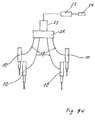
- FIG. 4 shows an embodiment in which one consists of several linear drives 10 Drive unit is formed. Each linear drive is controlled by an adjustable drive element 18 driven. It follows from FIG. 4 that the one shown there Arrangement can be seen as an example, since the linear drives 10 practically in each Position can be arranged to each other.
- the drive elements already mentioned 18 are connected to the output elements of a transfer case 22, which is driven by a motor 23. In a different version could the drive elements 18 are also coupled to a number of transfer cases 22, each transfer case 22 being driven by its own drive motor 23 can be, so that all linear drives 10 are driven. However, it is also conceivable that only certain linear drives 10 are driven if, for example the transfer case, or the transfer case 22 are switchable.
- a plurality of transfer cases 22 could have a motor assigned to each transfer case are, so that certain linear drives 10 are then put into operation could.
- the control of the drive motor 23 or the drive motors 23 takes place via a hand switch 24 and a correspondingly designed control unit 25.
- Such an embodiment can be used, for example, when Several components are adjustable in one piece of furniture.
- Essential is the drive of the spindle from the drive motor 16 via the adjustable Drive element 18.
Landscapes
- Engineering & Computer Science (AREA)
- General Engineering & Computer Science (AREA)
- Mechanical Engineering (AREA)
- Health & Medical Sciences (AREA)
- General Health & Medical Sciences (AREA)
- Nursing (AREA)
- Power Engineering (AREA)
- Transmission Devices (AREA)
- Connection Of Motors, Electrical Generators, Mechanical Devices, And The Like (AREA)
- Power-Operated Mechanisms For Wings (AREA)
Applications Claiming Priority (2)
| Application Number | Priority Date | Filing Date | Title |
|---|---|---|---|
| DE29914126U DE29914126U1 (de) | 1999-08-12 | 1999-08-12 | Linearantrieb |
| DE29914126U | 1999-08-12 |
Publications (2)
| Publication Number | Publication Date |
|---|---|
| EP1076399A2 true EP1076399A2 (fr) | 2001-02-14 |
| EP1076399A3 EP1076399A3 (fr) | 2003-08-20 |
Family
ID=8077435
Family Applications (1)
| Application Number | Title | Priority Date | Filing Date |
|---|---|---|---|
| EP00116471A Withdrawn EP1076399A3 (fr) | 1999-08-12 | 2000-07-29 | Actionneur linéaire |
Country Status (4)
| Country | Link |
|---|---|
| US (1) | US6452293B1 (fr) |
| EP (1) | EP1076399A3 (fr) |
| JP (1) | JP2001078386A (fr) |
| DE (1) | DE29914126U1 (fr) |
Cited By (1)
| Publication number | Priority date | Publication date | Assignee | Title |
|---|---|---|---|---|
| EP1467468A3 (fr) * | 2003-04-08 | 2007-01-24 | Reac Ab | Elément de réglage pour motoréducteur |
Families Citing this family (7)
| Publication number | Priority date | Publication date | Assignee | Title |
|---|---|---|---|---|
| DK1902237T3 (da) * | 2005-07-13 | 2014-04-22 | Linak As | Aktuatorsystem |
| GB0514392D0 (en) * | 2005-07-13 | 2005-08-17 | Huntleigh Technology Plc | Actuator assembly and override control system |
| AU2011213903B9 (en) * | 2005-07-13 | 2013-05-30 | Linak A/S | Actuator assembly and bed |
| US7579721B2 (en) * | 2007-07-13 | 2009-08-25 | Hiwin Mikrosystem Corp. | Chain support structure for a planar motor |
| FR2946632B1 (fr) † | 2009-06-11 | 2015-05-29 | Sidel Participations | Installation de convoyage comprenant au moins un couloir courbe |
| WO2014040728A1 (fr) * | 2012-09-14 | 2014-03-20 | De Werth Group Ag | Entraînement de meuble à moteur électrique |
| TWI803397B (zh) * | 2022-07-21 | 2023-05-21 | 施權航 | 電動床 |
Family Cites Families (15)
| Publication number | Priority date | Publication date | Assignee | Title |
|---|---|---|---|---|
| US4182078A (en) * | 1978-02-13 | 1980-01-08 | Merit Plastics, Inc. | Window regulator and drive assembly |
| US4267668A (en) * | 1979-04-26 | 1981-05-19 | Natinsky Ronald E | Power window lift assembly |
| DE3119103A1 (de) * | 1981-05-14 | 1982-12-02 | Samaritter, geb. Kornasowa, Vera, 5090 Leverkusen | Vorrichtung zum verstellen von fenstern, fenstertueren und oder auch, verfahren zu ihrer ausfuehrung |
| JPS59163608A (ja) * | 1983-03-08 | 1984-09-14 | Hitachi Koki Co Ltd | ジグソ− |
| DE3618266C1 (en) * | 1986-05-30 | 1987-10-15 | Lemfoerder Metallwaren Ag | Adjustable steering column for motor vehicles |
| DE3636514A1 (de) * | 1986-10-27 | 1988-05-05 | Fraunhofer Ges Forschung | Schraubvorrichtung |
| DE3841460A1 (de) * | 1988-12-09 | 1990-06-13 | Willibald Neudert | Vorrichtung zur uebertragung von mechanischen kraeften in laengsrichtung mittels einer biegsamen stahldrahtspiralwelle |
| US4989323A (en) * | 1989-06-05 | 1991-02-05 | Caspro Mechanical Technologies, Inc. | Portable power unit for various power tolls |
| US5233247A (en) * | 1991-07-16 | 1993-08-03 | The United States Of America As Represented By The Secretary Of The Navy | Precision drive and speed reduction device |
| US5474520A (en) * | 1994-03-14 | 1995-12-12 | Bittikofer; Raymond P. | Apparatus for producing multiple motions |
| GB2293398A (en) * | 1994-09-22 | 1996-03-27 | Ford Motor Co | Electrically operated vehicle door windows |
| US5791622A (en) * | 1996-07-02 | 1998-08-11 | Lear Corporation | Vehicle power seat adjuster with flex cable guides |
| JP3357074B2 (ja) * | 1996-08-09 | 2002-12-16 | ケーニツヒ ウント バウエル アクチエンゲゼルシヤフト | 胴駆動装置 |
| US5820464A (en) * | 1997-01-03 | 1998-10-13 | S.S. White Technologies Inc. | Flexible shaft assembly |
| CN1285900A (zh) * | 1997-12-31 | 2001-02-28 | 杰克·W·罗马诺 | 用于将钻动能量传送到切削构件上的方法和设备 |
-
1999
- 1999-08-12 DE DE29914126U patent/DE29914126U1/de not_active Expired - Lifetime
-
2000
- 2000-07-29 EP EP00116471A patent/EP1076399A3/fr not_active Withdrawn
- 2000-08-08 JP JP2000240200A patent/JP2001078386A/ja active Pending
- 2000-08-11 US US09/636,713 patent/US6452293B1/en not_active Expired - Fee Related
Cited By (3)
| Publication number | Priority date | Publication date | Assignee | Title |
|---|---|---|---|---|
| EP1467468A3 (fr) * | 2003-04-08 | 2007-01-24 | Reac Ab | Elément de réglage pour motoréducteur |
| US7284458B2 (en) | 2003-04-08 | 2007-10-23 | Reac Ab | Adjusting element device |
| USRE40870E1 (en) | 2003-04-08 | 2009-08-18 | Reac Ab | Adjusting element device |
Also Published As
| Publication number | Publication date |
|---|---|
| JP2001078386A (ja) | 2001-03-23 |
| DE29914126U1 (de) | 1999-10-14 |
| EP1076399A3 (fr) | 2003-08-20 |
| US6452293B1 (en) | 2002-09-17 |
Similar Documents
| Publication | Publication Date | Title |
|---|---|---|
| DE69400262T2 (de) | Motorgetriebenes Gerät und Mechanismus dafür | |
| EP0563583A1 (fr) | Commande à moteur,en particulier commande à moteur électrique pour fenêtre ou toit-ouvrant | |
| EP0428895B1 (fr) | Dispositif d'entraînement | |
| DE19931818A1 (de) | Mehrstufiges Stirnradgetriebe | |
| DE69524172T2 (de) | Kraftgetriebenes Werkzeug mit Wellendurchbiegungsbegrenzer | |
| DE10254127B4 (de) | Elektromotorischer Möbelantrieb zum Verstellen von Teilen eines Möbels relativ zueinander | |
| EP1076399A2 (fr) | Actionneur linéaire | |
| EP0121063B1 (fr) | Entraînement en rotation réglable sans jeu d'au moins un arbre principal pour manipulateurs | |
| DE3420918C2 (de) | Doppelschneckenextruder | |
| EP1097657B1 (fr) | Unité téléscopique d'entraínement | |
| DE69808648T2 (de) | Kraftangetriebenes werkzeug mit verlängerter antriebswelle | |
| EP1177391B1 (fr) | Transmission a arbre de renvoi double | |
| DE60301648T2 (de) | Antriebsvorrichtung für Werkzeugmaschinen | |
| DE10254129B4 (de) | Elektromotorischer Möbelantrieb zum Verstellen von Teilen eines Möbels relativ zueinander | |
| DE19622060C1 (de) | Spielfreier Antrieb | |
| DE20108885U1 (de) | Integrierbarer Verstellantrieb | |
| DE102009006482B4 (de) | Getriebe mit Gegenlager | |
| DE19650716C1 (de) | Exzentergetriebe | |
| DE69603621T2 (de) | Getriebe | |
| DE19823352C2 (de) | Miniaturisierte Linearantriebsvorrichtung | |
| DE19809014C2 (de) | Doppelkurbeltrieb | |
| DE102018108480B3 (de) | Heckspoiler-Stellantrieb | |
| DE10107601A1 (de) | Schneckenbauteil | |
| DE29802536U1 (de) | Elektromotorischer Linearantrieb | |
| DE10254125A1 (de) | Elektromotorischer Möbelantrieb zum Verstellen von Teilen eines Möbels relativ zueinander |
Legal Events
| Date | Code | Title | Description |
|---|---|---|---|
| PUAI | Public reference made under article 153(3) epc to a published international application that has entered the european phase |
Free format text: ORIGINAL CODE: 0009012 |
|
| AK | Designated contracting states |
Kind code of ref document: A2 Designated state(s): AT BE CH CY DE DK ES FI FR GB GR IE IT LI LU MC NL PT SE |
|
| AX | Request for extension of the european patent |
Free format text: AL;LT;LV;MK;RO;SI |
|
| PUAL | Search report despatched |
Free format text: ORIGINAL CODE: 0009013 |
|
| AK | Designated contracting states |
Designated state(s): AT BE CH CY DE DK ES FI FR GB GR IE IT LI LU MC NL PT SE |
|
| AX | Request for extension of the european patent |
Extension state: AL LT LV MK RO SI |
|
| RIC1 | Information provided on ipc code assigned before grant |
Ipc: 7F 16C 1/12 B Ipc: 7H 02K 7/06 B Ipc: 7H 02K 7/10 A |
|
| AKX | Designation fees paid |
Designated state(s): AT BE CH CY DE DK ES FI FR GB GR IE IT LI LU MC NL PT SE |
|
| STAA | Information on the status of an ep patent application or granted ep patent |
Free format text: STATUS: THE APPLICATION IS DEEMED TO BE WITHDRAWN |
|
| 18D | Application deemed to be withdrawn |
Effective date: 20040221 |