EP1076468A2 - Übertragungseinrichtung für IP-Paketen - Google Patents
Übertragungseinrichtung für IP-Paketen Download PDFInfo
- Publication number
- EP1076468A2 EP1076468A2 EP00117455A EP00117455A EP1076468A2 EP 1076468 A2 EP1076468 A2 EP 1076468A2 EP 00117455 A EP00117455 A EP 00117455A EP 00117455 A EP00117455 A EP 00117455A EP 1076468 A2 EP1076468 A2 EP 1076468A2
- Authority
- EP
- European Patent Office
- Prior art keywords
- optical path
- optical
- signals
- signal
- wavelength
- Prior art date
- Legal status (The legal status is an assumption and is not a legal conclusion. Google has not performed a legal analysis and makes no representation as to the accuracy of the status listed.)
- Granted
Links
Images





Classifications
-
- H—ELECTRICITY
- H04—ELECTRIC COMMUNICATION TECHNIQUE
- H04Q—SELECTING
- H04Q11/00—Selecting arrangements for multiplex systems
- H04Q11/0001—Selecting arrangements for multiplex systems using optical switching
- H04Q11/0005—Switch and router aspects
-
- H—ELECTRICITY
- H04—ELECTRIC COMMUNICATION TECHNIQUE
- H04J—MULTIPLEX COMMUNICATION
- H04J2203/00—Aspects of optical multiplex systems other than those covered by H04J14/05 and H04J14/07
- H04J2203/0001—Provisions for broadband connections in integrated services digital network using frames of the Optical Transport Network [OTN] or using synchronous transfer mode [STM], e.g. SONET, SDH
- H04J2203/0089—Multiplexing, e.g. coding, scrambling, SONET
-
- H—ELECTRICITY
- H04—ELECTRIC COMMUNICATION TECHNIQUE
- H04Q—SELECTING
- H04Q11/00—Selecting arrangements for multiplex systems
- H04Q11/0001—Selecting arrangements for multiplex systems using optical switching
- H04Q11/0062—Network aspects
- H04Q11/0066—Provisions for optical burst or packet networks
-
- H—ELECTRICITY
- H04—ELECTRIC COMMUNICATION TECHNIQUE
- H04Q—SELECTING
- H04Q11/00—Selecting arrangements for multiplex systems
- H04Q11/0001—Selecting arrangements for multiplex systems using optical switching
- H04Q11/0062—Network aspects
- H04Q11/0071—Provisions for the electrical-optical layer interface
-
- H—ELECTRICITY
- H04—ELECTRIC COMMUNICATION TECHNIQUE
- H04Q—SELECTING
- H04Q11/00—Selecting arrangements for multiplex systems
- H04Q11/0001—Selecting arrangements for multiplex systems using optical switching
- H04Q11/0005—Switch and router aspects
- H04Q2011/0007—Construction
- H04Q2011/0011—Construction using wavelength conversion
Definitions
- the present invention relates to a packet transmission equipment for a packet transmission system which implements communications through exchanges of packets as communication units. More particularly, the invention pertains to an IP packet transmission equipment for use in an IP communication network which carries out communications through exchanges of IP (Internet Protocol) packets as communication units.
- IP Internet Protocol
- IP packets are transmitted over an ISDN system, but high-capacity transmission over a leased circuit utilizes an IP packet transmission equipment based on a technique called an IP over SDH (Synchronous Digital Hierarchy) which stores IP packets in an SDH path payload area.
- IP over SDH Synchronous Digital Hierarchy
- IP packets are accommodated in the SDH path payload for each destination, and IP routers at remote locations are interconnected over a SDH transmission network.
- SDH paths are multiplexed to construct an STM (Synchronous Transport Module) signal.
- the IP routers 600-1 to 600-4 are each connected to a local transmission liner of lower speed and lower capacity than a backbone transmission line BB, or to server equipment.
- the STM signal is transmitted over backbone transmission lines BB-1 to BB-7, and at SDH cross-connects 500-1 to 5004 on its way to destination, routing takes place for each SDH path signal so that the STM signal is sent to its desired destination.
- an optical transmission system which performs routing at the optical level to build a higher-capacity IP communication network unlike the conventional SDH transmission system of Fig. 1 which involves routing at the electrical level in SDH cross-connects.
- information is conveyed over the optical path transport network with IP packets accommodated in an optical path payload portion.
- wavelength routing is performed which sets routes to respective destinations of transmission signals on a wavelength-wise basis.
- Such an optical communication network is disclosed in, for example, K. Sato, S. Okamoto and H. Hadama, "Optical Path layer Technologies to Enhance B-ISDN Performance," ICC'93, May 23, 1993.
- Fig. 2 depicts a WDM (Wavelength Division Multiplexing) type optical communication channel disclosed in, for instance, Japanese Patent Application Laid-Open Gazette No. 7-67153. It is considered that the illustrated structure can be used for each cross-connect 500 in Fig. 1 to handle an optical signal.
- WDM Widelength Division Multiplexing
- wavelength-multiplexed signals WDMS provided to input optical backbone transmission lines OBB- 11 to OBB-14 are demultiplexed for each wavelength in wavelength demultiplexing parts 51-1 to 51-3, then the optical signals of the individual wavelengths are regenerated by optical regenerators 52-1 to 52-16, respectively, then the regenerated optical signals are cross-connected by optical switches 53-1 to 53-4 to predetermined routes and are multiplexed in wavelength multiplexing parts 54-1 to 54-4, from which the wavelength-multiplexed optical signals are provided to output optical backbone transmission lines OBB-21 to OBB-24.
- the optical regenerators 52-1 to 52-16 each convert the optical path signal of one wavelength to an electrical signal, and applies it to a laser light source, thereby generating an amplified and shaped optical path signal.
- each of the IP routers 600-1 to 600-4 in the transmission system of Fig. 1 are constructed to convert signals of arbitrary formats to IP packets and how they are connected to the cross-connect 600-1.
- the most common-sense way is to connect, for instance, the output of the IP router 600-1 to one of the input optical highways in Fig. 2 and apply the wavelength-multiplexed signal from the IP router 600-1.
- Such IP routers use laser light sources for the conversion of IP packets to optical path signals. The wavelengths of these laser light sources need to be always monitored and controlled together with the wavelengths of laser light sources used in the optical regenerators 52-1 to 52-16.
- laser light sources are provided in the IP routers.
- the optical signals generated by the laser light source in each IP router is regenerated by the laser light source of the optical regenerator in each optical cross-connect.
- an IP packet transmission equipment which is provided in a node of a transmission network containing backbone transmission lines and local transmission liners and transmits optical path signals between source and destination nodes via logically defined optical paths, said apparatus comprising:
- the optical regenerators corresponding to OTM/optical path signal conversion parts connected directly to the IP packet transmission equipment in the prior art example becomes unnecessary, and hence it is possible to construct an IP packet transmission equipment with a smaller number of laser light sources than in the prior art.
- Fig. 3 illustrates part of an IP packet transmission network in which IP packet transmission equipments 100-1, 100-2, 100-3, ... according to the present invention are connected by optical backbone transmission lines OBB.
- OBB optical backbone transmission lines
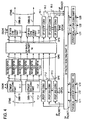
- Fig. 4 illustrates in block form a first embodiment of the IP packet transmission equipment according to the present invention.
- OTM Optical Transport Module signals
- NNI Network-Node-Interface
- Optical regenerators 13-1 to 13-6 convert the optical path signals OPS from the OTM/optical path signal conversion parts 11-1 and 11-2 to electrical signals, which are provided to laser light sources (not shown) of the same wavelengths as those of the input optical path signals OPS, by which they are amplified and shaped to restore the original optical path signals OPS.
- a physical layer/IP conversion part 15 is a means by which signals of arbitrary formats (SDH signals, ATM signals, ethernet signals, or the like) from branch transmission lines L11, L12 and L13, each formed by an arbitrary physical medium (a metal coaxial cable, optical finer, or the like), are converted to IP packets.
- the branch transmission lines L11, L12 and L13 are lower in speed and in capacity than the optical backbone transmission line, but they need not be limited specifically to such transmission lines and may be transmission lines equivalent to the backbone transmission line.
- An IP packet routing part 16 distributes the IP packets to routes according to their destinations.
- Optical path signal conversion parts 17-1, 17-2 and 17-3 convert the IP packets (electrical signals) to optical path signals OPS.
- An optical path switching part 14 cross-connect the regenerated optical path signals OPS from the optical regrnetators 13-1 to 13-6 and the optical path signals OPS from the Optical path signal conversion parts 17-1, 17-2 and 17-3 to optical path signal/OTM conversion parts 12-1 and 12-2 and optical path signal/IP conversion parts 18-1, 18-2 and 18-3 according to destinations of the input signals.
- optical path signals OPS provided to the optical path signal/OTM conversion parts 12-1 and 12-2 are multiplexed in wavelength and provided as OTM signals to output optical backbone transmission lines OBB-21 and OBB-22.
- the optical path signals OPS fed to the optical path signal/IP conversion parts 18-1, 18-2 and 18-3 are restored to IP packets (electrical signals), which are provided to the IP packet routing part 16.
- the IP packet routing part 16 distributes the IP packets to output route according to their destinations and applies them to an IP/physical layer conversion part 19.
- the IP/physical layer conversion part 19 converts the IP packets to signals of desired forms (such as SDH and ATM signals) and provides them to branch transmission lines L21, L22 and L23.
- the IP packet transmission equipment has a functional configuration in which optical cross-connects and IP routers are integrated and the outputs from the Optical path signal conversion parts 17-1, 17-2 and 17-3 are provided directly to the optical path switching part 14 for the reasons given just below.
- the optical path signals transmitted over a long distance via the optical backbone transmission lines have been attenuated and waveform-distorted, and hence they cannot be sent intact to the IP packet transmission equipment which constitutes the next node; therefore, the optical path signals are in need of amplification and shaping by the optical regenerators 13-1 to 13-6.
- the optical path signals OPS from the Optical path signal conversion parts 17-1, 17-2 and 17-3 are generated by converting the IP packets to optical path signals and are free from the waveform distortion by transmission, and hence they need not be regenerated. Accordingly, the required number of laser light sources used is smaller than in the case of connecting IP routers to the conventional transit transmission apparatus as depicted in Fig. 2. Besides, since it is unnecessary to employ an OTM/optical path signal conversion part and an optical path signal/OTM conversion part needed to adjust the input signal format in the case of connecting the conventional IP router and the optical cross-connect device, the scale of the IP packet transmission equipment can be reduced as a whole.
- FIG. 3 the operation of the first embodiment will be described below in connection with the IP packet transmission from the IP packet transmission equipment 100-1 to 100-3 via 100-2.
- This is a model in which an optical path is logically defined between the IP packet transmission equipmentes 100-1 and 100-3.
- the IP packet transmission equipmentes 100-1 to 100-3 each have the configuration depicted in Fig. 4.
- IP packet transmission equipment 100-1 which is the sending side in this case.
- Arbitrary signals (such as STM, ATM, or ethernet signals) input from the input branch transmission lines L11 to L13 are converted by the physical layer/IP conversion part 15 to IP packets, which are distributed by the IP packet routing part 14 on a packet-wise basis.
- IP packet input to the Optical path signal conversion part 17-1 is predetermined or predestined to be cross-connected by the optical path switching part 14 to the optical path signal/OTM conversion part 12-1 and thence carried to the IP packet transmission equipment 100-3.
- the Optical path signal conversion part 17-1 comprises, as depicted in Fig. 5A, an IP/optical path payload conversion part 17A, an optical path signal overhead insertion circuit 17B and a laser light source 17C.
- the IP/optical path payload conversion part 17A writes the input IP packets into an optical path payload area OPP in an optical path signal shown in Fig. 6.
- the optical path signal OPS is composed of a data string of 9 ⁇ (270 ⁇ N) bytes and an optical path overhead OPOH (OPS3) which is superimposed on the data string.
- the data string is divided into an optical path overhead area OPS1 (3 ⁇ (9 ⁇ N) bytes), an optical path overhead area OPS2 (5 ⁇ (9 ⁇ N) bytes), administrative unit pointer area AU (1 ⁇ (9 ⁇ N) bytes) and an optical path payload area OPP (9 ⁇ (261 ⁇ N) bytes).
- the overhead information includes, for example, an optical path trace identifier, connection control information about a signal label, administrative information about an optical path user channel and optical path states, and monitoring information such as a bit error rate monitoring byte and a state-of-synchronization monitoring byte.
- Such overhead information needed for each particular system is stored in predetermined overhead areas OPS1, OPS2 and OPS3.
- Such an optical signal format is disclosed in, for example, Satoru Okamoto, "Photonic Transport Network Architecture and OA & M Technologies to Create Large-Scale Robust Networks," IEEE Journal on Selected Areas in Communications, vol. 16, September, 1998, pp.995-1007 and Satoru Okamoto, "NNI Structure for WDM Optical Path Transport Network,” Proc. of the 1997 IEICE Conference, Sept., 1997, B-10-98.
- the optical path overhead area OPS3 is superimposed on an optical path payload signal through utilization of a technique of modulating a pilot tone or using optical CDMA, but in some cases the optical path overhead area OPS3 is not used.
- each IP packet is mapped into the optical path payload area OPP by copying its data string at a changed transmission rate, or by copying the data string after rendering the IP packet into an error correcting code.
- each IP packet is a variable-length data string, and the respective IP packets arrive at irregular time intervals.
- the optical path payload is a continuous data string, it is necessary to fill the blank between such discontinuously arriving individual IP packets with dummy data and delimit continuously arriving IP packets.
- PPP Point-to-Point Protocol
- PPP data strings called a PPP header (4 bytes) and a PPP trailer (2 bytes) are added to the IP packet to form a data string called a PPP frame.
- the PPP trailer is used to detect an error in PPP frame data.
- the IP packet is mapped into the optical path payload area OPP through the PPP frame.
- the IP packet can be taken out of the PPP frame by removing the PPP header and the PPP trailer.
- adjacent PPP frames are always separated by a data string of more than one byte which is "7E" in hexadecimal (i.e., "01111110").
- the above-mentioned dummy data is a data string of a required number of bytes which is "7E" in hexadecimal.
- PPP the IP packet is mapped into OPP through PPP. And the IP packet can be taken out by taking out PPP from OPP and then removing the PPP header and the PPP trailer.
- the optical path payload signal generated by the IP/optical path payload conversion part 17A is sent to the optical path signal overhead insertion circuit 17B.
- optical path overhead data OPOH is added to the optical path overhead areas OPS 1 and 2, and an administrative unit pointer AUP indicating the phase difference between the optical path signal format and the optical path payload is added to the optical path payload signal; thereafter, the optical path payload signal is provided to the laser light source 17C, wherein it is converted from electrical to optical form.
- the output wavelength of the laser light source may be either fixed or variable. In the case of a variable-wavelength output laser, it is assigned a wavelength predetermined so that the same wavelengths are not used on the output optical transmission line.
- optical path signal OPS is added to the optical path overhead area OPS3 to obtain the optical path signal OPS.
- the thus obtained optical path signals OPS is provided by the optical path switching part 14 to an output port predetermined for output to a desired output optical transmission line OTL-21, and is input to the optical path signal/OTM conversion part 12-1.
- the optical path signal/OTM conversion parts 12-1 and 12-2 each comprise an optical path signal multiplexing circuit 12A and an optical section overhead insertion circuit 12B as depicted in Fig. 7A.
- the input optical path signals OPS of different wavelengths, shown in Fig. 6, are multiplexed in wavelength (frequency) in the optical path signal multiplexing circuit 12A to form an OTM payload signal, which is applied to the optical section overhead insertion circuit 12B.
- optical section overhead insertion circuit 12B optical section overhead data OSOH is added to the OTM payload signal to generate an OTM signal, which is provided to an output optical transmission line OTL-1.
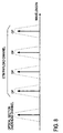
- the OTM signal thus generated is composed of an optical section overhead channel and an OTM payload channel as depicted in Fig. 8.
- OTM payload channel there is one more optical paths shown in Fig. 6.
- the OTM signal sent from the afore-mentioned IP packet transmission equipment 100-1 is provided via the input optical backbone transmission line OBB- 11 to the OTM/optical path signal conversion part 11-1, wherein it is separated into optical path signals OPS of respective wavelengths.
- the optical path signals OPS are regenerated by the optical regenerator 13-1, thereafter being cross-connected by the optical path switching part 14 to their predetermined routes.
- the optical path signals OPS input to the optical path signal/OTM conversion part 12-1 are wavelength-multiplexed to form an OTM signal, which is provided to the output optical backbone transmission line OBB-21, over which it is carried to the IP packet transmission equipment 100-3. That is, in the IP packet transmission equipment 100-2 no IP packet routing is performed but only optical path routing is carried out.
- the input OTM signal is fed to the OTM/optical path signal conversion part 11-1.
- the OTM/optical path signal conversion part 11-1 comprises an optical section separation circuit 11A and an optical path separation circuit 11B.
- the optical section overhead data OSOH of the input OTM signal is separated by the optical section overhead separation circuit 11A, and then only the OTM payload signal is applied to the optical path separation circuit 11B.
- the input OTM payload signal is separated in wavelength (frequency), and optical paths of individual wavelengths are output.
- the optical path signal OPS input to the optical regenerator 13-1 is regenerative-repeated and then provided to the optical path switching part 14.
- the operation from the optical path switching part 14 to the formation of the OTM signal by the optical path signal/OTM conversion part 12-1 is the same as the operation in the afore-mentioned IP packet transmission equipment 100-1.
- the OTM signal sent from the afore-mentioned IP packet transmission equipment 100-2 is input via the input optical backbone transmission line OBB-11 to the OTM/optical path signal conversion part 11-1, wherein the optical path signal OPS is extracted from the OTM signal, and it is applied to the optical regenerator 13-1.
- the optical path signal OPS is regenerated, and it is provided by the optical path switching part 14 to the optical path signal/IP conversion part 18-1, wherein the IP packet is taken out, and from which it is provided to the IP packet routing part 16.
- the operation from the OTM/optical path signal conversion part 11-1 to the optical path switching part 14 is the same as in the IP packet transmission equipment 100-2.
- the optical path signal OPS is provided to the optical path signal/IP conversion part 18-1.
- the optical path signal/IP conversion part 18-1 is made up of an optical path signal overhead separation circuit circuit 18A and an optical path payload/conversion part 18-B as depicted in Fig. 5B.
- the optical path signal OPS input to the optical path signal/IP conversion part 18-1 is fed to the optical path signal overhead separation circuit circuit 18A, wherein the optical path overhead area OPS3 is separated from the signal OPS.
- it is converted from electrical to optical form, by which the data of the optical path overhead area OPS1 and OPS2 is separated, and only the optical path payload portion is input to the optical payload/IP conversion part 18B using the administrative unit pointer AU.
- the optical path payload signal is subjected to speed changing, decoding and so on in the optical path payload/IP conversion part 18B, and the ultimate IP packet is provided to the IP packet routing part 16.
- IP packet transmission equipment it is possible, with the IP packet transmission equipment, to realize high-capacity IP communication between IP packet transmission equipmentes over an optical path transport network.
- Fig. 9 illustrates a second embodiment of the IP packet transmission equipment according to the present invention.
- This embodiment employs wavelength converters 21-1 to 21-6 in place of the optical regenerators 13-1 to 13-6 in the first embodiment shown in Fig. 4.
- This embodiment is identical in construction and operation with the first embodiment except the above.
- the wavelength converters 21-1 to 21-6 output optical signals of predetermined different wavelengths. AT this time, the wavelengths are converted, but the signals themselves are not converted.
- the optical signals from the wavelength converters 21-1 to 21-6 are cross-connected by the optical path switching part 14 to the optical path signal/OTM conversion parts 12-1, 12-2 and the optical path signal/IP conversion parts 18-1, 18-2, 18-3 through predetermined routes.
- the wavelength converters 21-1 to 21-6 may be any types of variable-wavelength converters, as long as they are capable of switching output wavelengths ⁇ 1 to ⁇ 6.
- wavelength converters permits selection of unused wavelengths at the time of selecting desired routes, and hence permits reduction of the required number of wavelengths as a whole.
- the IP packet transmission equipment is constructed by integrating the conventional optical cross-connect apparatus and the IP router so that the outputs of the Optical path signal conversion parts 17-1 to 17-3 of the IP router are connected directly to the optical path switching part 14. Accordingly, the OTM signal needed as an interface signal between the conventional optical path cross-connect apparatuses is unnecessary, and the OTM/optical path signal conversion parts and the optical path signal/OTM conversion parts of the prior art example can be dispensed with. Hence, the IP packet transmission equipment is highly economical in terms of the number of parts and monitoring/control.
Landscapes
- Engineering & Computer Science (AREA)
- Computer Networks & Wireless Communication (AREA)
- Data Exchanges In Wide-Area Networks (AREA)
- Optical Communication System (AREA)
- Use Of Switch Circuits For Exchanges And Methods Of Control Of Multiplex Exchanges (AREA)
Applications Claiming Priority (2)
| Application Number | Priority Date | Filing Date | Title |
|---|---|---|---|
| JP22839799 | 1999-08-12 | ||
| JP22839799A JP3538076B2 (ja) | 1999-08-12 | 1999-08-12 | パケット伝送装置 |
Publications (3)
| Publication Number | Publication Date |
|---|---|
| EP1076468A2 true EP1076468A2 (de) | 2001-02-14 |
| EP1076468A3 EP1076468A3 (de) | 2002-09-18 |
| EP1076468B1 EP1076468B1 (de) | 2004-12-22 |
Family
ID=16875836
Family Applications (1)
| Application Number | Title | Priority Date | Filing Date |
|---|---|---|---|
| EP00117455A Expired - Lifetime EP1076468B1 (de) | 1999-08-12 | 2000-08-11 | Übertragungseinrichtung für IP-Paketen |
Country Status (5)
| Country | Link |
|---|---|
| US (1) | US6701088B1 (de) |
| EP (1) | EP1076468B1 (de) |
| JP (1) | JP3538076B2 (de) |
| CA (1) | CA2315958C (de) |
| DE (1) | DE60016851T2 (de) |
Cited By (6)
| Publication number | Priority date | Publication date | Assignee | Title |
|---|---|---|---|---|
| WO2003067843A1 (en) * | 2002-02-06 | 2003-08-14 | Wuhan Fiberhome Networks Co., Ltd | Resilient multiple service ring |
| WO2005015944A1 (en) * | 2003-08-07 | 2005-02-17 | Telecom Italia S.P.A. | Packet and optical routing equipment and method |
| EP1523118A1 (de) * | 2003-10-09 | 2005-04-13 | Alcatel | Optische Paketübertragung |
| US7260091B2 (en) | 2001-09-26 | 2007-08-21 | Fujitsu Limited | Transmission equipment having a packet switching function |
| US7409158B2 (en) | 2003-02-04 | 2008-08-05 | Samsung Electronics Co., Ltd. | Large-capacity optical router using electric buffer |
| US7778162B2 (en) | 2002-11-06 | 2010-08-17 | Wuhan Fiberhome Networks Co. Ltd. | Multiple service ring of N-ringlet structure based on multiple FE, GE and 10GE |
Families Citing this family (14)
| Publication number | Priority date | Publication date | Assignee | Title |
|---|---|---|---|---|
| WO2001086998A1 (en) * | 2000-05-11 | 2001-11-15 | Btg International Limited | Optical transport networks |
| US7613183B1 (en) | 2000-10-31 | 2009-11-03 | Foundry Networks, Inc. | System and method for router data aggregation and delivery |
| JP4433624B2 (ja) * | 2001-02-28 | 2010-03-17 | 日本電気株式会社 | 通信ネットワーク、集中制御装置、通信ノード装置及びそれらに用いる状態通知情報相互交換方法 |
| JP3734762B2 (ja) * | 2002-03-14 | 2006-01-11 | 富士通株式会社 | Wdm装置 |
| FR2846185B1 (fr) * | 2002-10-21 | 2005-02-25 | Cit Alcatel | Routeur perfectionne a insertion et/ou extraction de ressources |
| US7797444B2 (en) | 2003-02-03 | 2010-09-14 | Nippon Telegraph And Telephone Corporation | Data transfer apparatus and data transfer system |
| US7715363B1 (en) * | 2003-03-10 | 2010-05-11 | Sprint Communications Company L.P. | Wide area network with a large number of endpoints and a high bandwidth optical backbone |
| US20040260841A1 (en) * | 2003-06-19 | 2004-12-23 | Mathew Tisson K. | Method, apparatus, and system for internet protocol communication over intelligent platform management bus |
| KR100581061B1 (ko) * | 2003-11-10 | 2006-05-22 | 한국전자통신연구원 | 광전달망 시스템에서 광감시채널의 광채널 오버헤드스위칭 장치 및 이를 이용한 광채널 유지보수 신호 전달장치 |
| US7894426B2 (en) * | 2005-02-04 | 2011-02-22 | Hewlett-Packard Development Company, L.P. | Conduit port for network chips |
| US8327031B2 (en) * | 2005-02-08 | 2012-12-04 | Hewlett-Packard Development Company, L.P. | Support chip for handling network chips on a network device |
| US7835393B2 (en) * | 2008-01-16 | 2010-11-16 | Applied Micro Circuits Corporation | System and method for converting multichannel time division multiplexed data into packets |
| JP5850313B2 (ja) * | 2011-10-05 | 2016-02-03 | 国立大学法人名古屋大学 | 波長群光パスクロスコネクト装置 |
| US20160112271A1 (en) * | 2014-10-15 | 2016-04-21 | Juniper Networks, Inc. | Controller-to-controller interface for multi-layer network abstraction |
Family Cites Families (8)
| Publication number | Priority date | Publication date | Assignee | Title |
|---|---|---|---|---|
| US5986783A (en) * | 1997-02-10 | 1999-11-16 | Optical Networks, Inc. | Method and apparatus for operation, protection, and restoration of heterogeneous optical communication networks |
| US6111673A (en) * | 1998-07-17 | 2000-08-29 | Telcordia Technologies, Inc. | High-throughput, low-latency next generation internet networks using optical tag switching |
| EP0986226B1 (de) * | 1998-09-11 | 2007-01-17 | Hitachi, Ltd. | IP-Paketkommunikationsvorrichtung |
| US6317236B1 (en) * | 1998-09-24 | 2001-11-13 | Cisco Photonics Italy, S.R.L. | Method and apparatus for transmitting an internet protocol (IP) packet within a fiber optic network |
| JP2000115133A (ja) | 1998-10-05 | 2000-04-21 | Fujitsu Ltd | 光パスクロスコネクト装置及び光ネットワーク |
| US6271946B1 (en) * | 1999-01-25 | 2001-08-07 | Telcordia Technologies, Inc. | Optical layer survivability and security system using optical label switching and high-speed optical header generation and detection |
| JP3773380B2 (ja) * | 1999-07-28 | 2006-05-10 | 沖電気工業株式会社 | ノード制御装置、ノード装置、光ネットワークシステム及び光パス設定方法 |
| JP3761362B2 (ja) * | 1999-07-28 | 2006-03-29 | 沖電気工業株式会社 | ノード制御装置、ノード装置、光ネットワークシステム及び光パス設定方法 |
-
1999
- 1999-08-12 JP JP22839799A patent/JP3538076B2/ja not_active Expired - Lifetime
-
2000
- 2000-08-11 EP EP00117455A patent/EP1076468B1/de not_active Expired - Lifetime
- 2000-08-11 CA CA002315958A patent/CA2315958C/en not_active Expired - Lifetime
- 2000-08-11 DE DE60016851T patent/DE60016851T2/de not_active Expired - Lifetime
- 2000-08-14 US US09/636,822 patent/US6701088B1/en not_active Expired - Lifetime
Cited By (10)
| Publication number | Priority date | Publication date | Assignee | Title |
|---|---|---|---|---|
| US7260091B2 (en) | 2001-09-26 | 2007-08-21 | Fujitsu Limited | Transmission equipment having a packet switching function |
| WO2003067843A1 (en) * | 2002-02-06 | 2003-08-14 | Wuhan Fiberhome Networks Co., Ltd | Resilient multiple service ring |
| US7382789B2 (en) | 2002-02-06 | 2008-06-03 | Wuhan Fiberhome Networks Co. Ltd. | Resilient multiple service ring |
| US7778162B2 (en) | 2002-11-06 | 2010-08-17 | Wuhan Fiberhome Networks Co. Ltd. | Multiple service ring of N-ringlet structure based on multiple FE, GE and 10GE |
| US7409158B2 (en) | 2003-02-04 | 2008-08-05 | Samsung Electronics Co., Ltd. | Large-capacity optical router using electric buffer |
| CN100420309C (zh) * | 2003-02-04 | 2008-09-17 | 三星电子株式会社 | 利用电缓冲器的大容量光路由器 |
| WO2005015944A1 (en) * | 2003-08-07 | 2005-02-17 | Telecom Italia S.P.A. | Packet and optical routing equipment and method |
| US7925165B2 (en) | 2003-08-07 | 2011-04-12 | Telecom Italia S.P.A. | Packet and optical routing equipment and method |
| EP1523118A1 (de) * | 2003-10-09 | 2005-04-13 | Alcatel | Optische Paketübertragung |
| US7535837B2 (en) | 2003-10-09 | 2009-05-19 | Alcatel | Optical packet transmission |
Also Published As
| Publication number | Publication date |
|---|---|
| DE60016851D1 (de) | 2005-01-27 |
| JP2001053803A (ja) | 2001-02-23 |
| DE60016851T2 (de) | 2005-12-01 |
| CA2315958A1 (en) | 2001-02-12 |
| CA2315958C (en) | 2005-08-09 |
| US6701088B1 (en) | 2004-03-02 |
| EP1076468B1 (de) | 2004-12-22 |
| JP3538076B2 (ja) | 2004-06-14 |
| EP1076468A3 (de) | 2002-09-18 |
Similar Documents
| Publication | Publication Date | Title |
|---|---|---|
| EP1076468B1 (de) | Übertragungseinrichtung für IP-Paketen | |
| Berthold et al. | Optical networking: Past, present, and future | |
| Mouftah et al. | Optical networks: architecture and survivability | |
| JP4511557B2 (ja) | 光通信のための方法、装置及びシステム | |
| US7280758B2 (en) | Optical multi-ring network for burst data communication | |
| TWI277311B (en) | Architecture, method and system of WDM-based photonic burst switched networks | |
| Cinkler | Traffic and/spl lambda/grooming | |
| CN102572618B (zh) | 一种基于g.709的多级复用路由控制方法和网关网元 | |
| US6731876B1 (en) | Packet transmission device and packet transmission system | |
| EP0856964B1 (de) | Vorrichtung zum Beendigung eines optischen Pfades | |
| JP2020014182A (ja) | 伝送装置 | |
| US20050135385A1 (en) | Method and apparatus for digital cross connect | |
| EP2552073B1 (de) | Auf g.709 basierendes mehrstufiges multiplex-routing-steuerverfahren und gateway-netzwerkelement | |
| US7362777B2 (en) | Concatenated transmission of synchronous data | |
| Sato et al. | Photonic transport technologies to create robust backbone networks | |
| JP4704316B2 (ja) | 光伝送システムおよび方法 | |
| Okamoto et al. | Inter-network interface for photonic transport networks and SDH transport networks | |
| Smith et al. | Evolution scenarios for optical telecommunication networks using multiwavelength transmission | |
| JP3189820B2 (ja) | パケット伝送装置及びパケット伝送システム | |
| CN1832383B (zh) | 一种业务信号节点交叉调度方法及节点交叉装置 | |
| JP3324988B2 (ja) | 光パス信号終端装置および光パス信号装置 | |
| Strand | Optical network architecture evolution | |
| JP3324970B2 (ja) | 光パス信号端局装置 | |
| Seetharaman | IP over DWDM | |
| Watanabe et al. | Robust IP backbone network utilizing WDM optical paths |
Legal Events
| Date | Code | Title | Description |
|---|---|---|---|
| PUAI | Public reference made under article 153(3) epc to a published international application that has entered the european phase |
Free format text: ORIGINAL CODE: 0009012 |
|
| 17P | Request for examination filed |
Effective date: 20000811 |
|
| AK | Designated contracting states |
Kind code of ref document: A2 Designated state(s): AT BE CH CY DE DK ES FI FR GB GR IE IT LI LU MC NL PT SE |
|
| AX | Request for extension of the european patent |
Free format text: AL;LT;LV;MK;RO;SI |
|
| PUAL | Search report despatched |
Free format text: ORIGINAL CODE: 0009013 |
|
| AK | Designated contracting states |
Kind code of ref document: A3 Designated state(s): AT BE CH CY DE DK ES FI FR GB GR IE IT LI LU MC NL PT SE |
|
| AX | Request for extension of the european patent |
Free format text: AL;LT;LV;MK;RO;SI |
|
| AKX | Designation fees paid |
Designated state(s): DE FR GB |
|
| 17Q | First examination report despatched |
Effective date: 20030905 |
|
| GRAP | Despatch of communication of intention to grant a patent |
Free format text: ORIGINAL CODE: EPIDOSNIGR1 |
|
| GRAS | Grant fee paid |
Free format text: ORIGINAL CODE: EPIDOSNIGR3 |
|
| GRAA | (expected) grant |
Free format text: ORIGINAL CODE: 0009210 |
|
| AK | Designated contracting states |
Kind code of ref document: B1 Designated state(s): DE FR GB |
|
| REG | Reference to a national code |
Ref country code: GB Ref legal event code: FG4D |
|
| REG | Reference to a national code |
Ref country code: IE Ref legal event code: FG4D |
|
| REF | Corresponds to: |
Ref document number: 60016851 Country of ref document: DE Date of ref document: 20050127 Kind code of ref document: P |
|
| PLBE | No opposition filed within time limit |
Free format text: ORIGINAL CODE: 0009261 |
|
| STAA | Information on the status of an ep patent application or granted ep patent |
Free format text: STATUS: NO OPPOSITION FILED WITHIN TIME LIMIT |
|
| ET | Fr: translation filed | ||
| 26N | No opposition filed |
Effective date: 20050923 |
|
| REG | Reference to a national code |
Ref country code: FR Ref legal event code: PLFP Year of fee payment: 17 |
|
| REG | Reference to a national code |
Ref country code: FR Ref legal event code: PLFP Year of fee payment: 18 |
|
| REG | Reference to a national code |
Ref country code: FR Ref legal event code: PLFP Year of fee payment: 19 |
|
| PGFP | Annual fee paid to national office [announced via postgrant information from national office to epo] |
Ref country code: FR Payment date: 20190822 Year of fee payment: 20 Ref country code: DE Payment date: 20190822 Year of fee payment: 20 |
|
| PGFP | Annual fee paid to national office [announced via postgrant information from national office to epo] |
Ref country code: GB Payment date: 20190821 Year of fee payment: 20 |
|
| REG | Reference to a national code |
Ref country code: DE Ref legal event code: R071 Ref document number: 60016851 Country of ref document: DE |
|
| REG | Reference to a national code |
Ref country code: GB Ref legal event code: PE20 Expiry date: 20200810 |
|
| PG25 | Lapsed in a contracting state [announced via postgrant information from national office to epo] |
Ref country code: GB Free format text: LAPSE BECAUSE OF EXPIRATION OF PROTECTION Effective date: 20200810 |