EP1076509B1 - Spektroskopische messungen an lichtstreuendem prüfgut mittels integrations -hohlraum - Google Patents
Spektroskopische messungen an lichtstreuendem prüfgut mittels integrations -hohlraum Download PDFInfo
- Publication number
- EP1076509B1 EP1076509B1 EP96941550A EP96941550A EP1076509B1 EP 1076509 B1 EP1076509 B1 EP 1076509B1 EP 96941550 A EP96941550 A EP 96941550A EP 96941550 A EP96941550 A EP 96941550A EP 1076509 B1 EP1076509 B1 EP 1076509B1
- Authority
- EP
- European Patent Office
- Prior art keywords
- cavity
- interior
- ports
- integrating
- radiation
- Prior art date
- Legal status (The legal status is an assumption and is not a legal conclusion. Google has not performed a legal analysis and makes no representation as to the accuracy of the status listed.)
- Expired - Lifetime
Links
Images

Classifications
-
- G—PHYSICS
- G01—MEASURING; TESTING
- G01N—INVESTIGATING OR ANALYSING MATERIALS BY DETERMINING THEIR CHEMICAL OR PHYSICAL PROPERTIES
- G01N21/00—Investigating or analysing materials by the use of optical means, i.e. using sub-millimetre waves, infrared, visible or ultraviolet light
- G01N21/17—Systems in which incident light is modified in accordance with the properties of the material investigated
- G01N21/47—Scattering, i.e. diffuse reflection
- G01N21/4738—Diffuse reflection, e.g. also for testing fluids, fibrous materials
- G01N21/474—Details of optical heads therefor, e.g. using optical fibres
-
- A—HUMAN NECESSITIES
- A61—MEDICAL OR VETERINARY SCIENCE; HYGIENE
- A61B—DIAGNOSIS; SURGERY; IDENTIFICATION
- A61B5/00—Measuring for diagnostic purposes; Identification of persons
- A61B5/145—Measuring characteristics of blood in vivo, e.g. gas concentration or pH-value ; Measuring characteristics of body fluids or tissues, e.g. interstitial fluid or cerebral tissue
- A61B5/14532—Measuring characteristics of blood in vivo, e.g. gas concentration or pH-value ; Measuring characteristics of body fluids or tissues, e.g. interstitial fluid or cerebral tissue for measuring glucose, e.g. by tissue impedance measurement
-
- A—HUMAN NECESSITIES
- A61—MEDICAL OR VETERINARY SCIENCE; HYGIENE
- A61B—DIAGNOSIS; SURGERY; IDENTIFICATION
- A61B5/00—Measuring for diagnostic purposes; Identification of persons
- A61B5/145—Measuring characteristics of blood in vivo, e.g. gas concentration or pH-value ; Measuring characteristics of body fluids or tissues, e.g. interstitial fluid or cerebral tissue
- A61B5/1455—Measuring characteristics of blood in vivo, e.g. gas concentration or pH-value ; Measuring characteristics of body fluids or tissues, e.g. interstitial fluid or cerebral tissue using optical sensors, e.g. spectral photometrical oximeters
-
- A—HUMAN NECESSITIES
- A61—MEDICAL OR VETERINARY SCIENCE; HYGIENE
- A61B—DIAGNOSIS; SURGERY; IDENTIFICATION
- A61B5/00—Measuring for diagnostic purposes; Identification of persons
- A61B5/68—Arrangements of detecting, measuring or recording means, e.g. sensors, in relation to patient
- A61B5/6801—Arrangements of detecting, measuring or recording means, e.g. sensors, in relation to patient specially adapted to be attached to or worn on the body surface
- A61B5/6813—Specially adapted to be attached to a specific body part
- A61B5/6825—Hand
- A61B5/6826—Finger
-
- A—HUMAN NECESSITIES
- A61—MEDICAL OR VETERINARY SCIENCE; HYGIENE
- A61B—DIAGNOSIS; SURGERY; IDENTIFICATION
- A61B5/00—Measuring for diagnostic purposes; Identification of persons
- A61B5/68—Arrangements of detecting, measuring or recording means, e.g. sensors, in relation to patient
- A61B5/6801—Arrangements of detecting, measuring or recording means, e.g. sensors, in relation to patient specially adapted to be attached to or worn on the body surface
- A61B5/683—Means for maintaining contact with the body
- A61B5/6838—Clamps or clips
-
- G—PHYSICS
- G01—MEASURING; TESTING
- G01N—INVESTIGATING OR ANALYSING MATERIALS BY DETERMINING THEIR CHEMICAL OR PHYSICAL PROPERTIES
- G01N21/00—Investigating or analysing materials by the use of optical means, i.e. using sub-millimetre waves, infrared, visible or ultraviolet light
- G01N21/17—Systems in which incident light is modified in accordance with the properties of the material investigated
- G01N21/47—Scattering, i.e. diffuse reflection
- G01N21/49—Scattering, i.e. diffuse reflection within a body or fluid
-
- G—PHYSICS
- G01—MEASURING; TESTING
- G01N—INVESTIGATING OR ANALYSING MATERIALS BY DETERMINING THEIR CHEMICAL OR PHYSICAL PROPERTIES
- G01N2201/00—Features of devices classified in G01N21/00
- G01N2201/06—Illumination; Optics
- G01N2201/065—Integrating spheres
Definitions
- the field of invention concerns the spectrophotometric determination of the concentration of substances in a light scattering sample.
- assessing glucose concentration in tissues of a patient by measuring the near infrared absorption by glucose in situ typically using a finger as the tissue sample for analysis.
- Spectroscopic measurement usually consists of an optical instrument which generates at least one light beam whose spectral content can be controlled, analyzed and measured in the presence of a sample and can be compared with the spectral content of the same beam in the absence of sample, or other light beam, acting as a reference.
- spectral variation of the detected optical signal in relation to a reference beam can provide information concerning the chemical composition of the sample. For such determinations it is critical to establish conditions which minimize extraneous factors which affect the signal. This is generally achieved by use of an optical system with a parallel test beam and by using samples in layers of pre-determined thickness. This geometry is intended to assure that the intensity of light detected by a photodetector does not depend on sample position, including small rotations or shift.
- the information can be used to identify that substance and is particularly useful in identifying the substance in samples where the components of the sample, or target, are unknown. Relative variations in absorption spectra may be used to provide information concerning the concentration of the substance.
- This technique is based on a number of assumptions. It assumes that the conditions for light propagation remain unchanged, i.e., the light beam does not change geometry. It also assumes that observed losses in light transmitted through the sample are caused only by absorption. In addition, this approach assumes that losses in detected signal depend on the thickness of the absorbing layer and the extinction coefficient (used for mathematical description of absorbance of the analyzed substance) which is proportional to the concentration of the absorber.
- an integrated cavity is an "emptiness" with non- absorbing strongly scattering walls which scatter light in a uniform fashion.
- a standard integrating cavity known as an integrating sphere, has the shape of a sphere with two or three ports depending on the application. One port is used to provide light to the cavity; the second allows light to reach some kind of photodetector (for example, it can be a spectrophotometer); and a third, optional port is provided to secure interaction of light with a target.
- photodetector for example, it can be a spectrophotometer
- a third, optional port is provided to secure interaction of light with a target.
- There can be variations in respect of the cavity including, shape of the cavity, position of the light source inside or outside the cavity, position of the target and the photodetector.
- small means small enough to minimally affect the uniformity of irradiance in the cavity.
- a sample must be positioned in such a way that light from a source cannot reach it directly, otherwise, nonuniform irradiance of the target is observed, and this is contrary to the requirement of uniform illumination. Consequently, use of an integrating cavity to measure absorption by a light scattering target requires a small target and that it be placed inside a cavity in a way so as to prevent direct coupling of light from a light output hole, or source, and target. In such cases the amount of light which has interacted with the sample reaching a photodetector is very small in comparison with light which has not undergone interaction with the sample.
- Dynamic range can be increased by reducing the amount of light which reaches the photodetector without interacting with the sample. Practically this may be achieved by filling the cavity with sample.
- a cavity with semitransparent diffusely scattering walls was filled with the test liquid and was placed inside another cavity.
- the walls of the first cavity could be considered as an additional integrating cavity, thus, in totality it could be considered as three cavities, one inside the other.
- the role of the external cavity is to redistribute available light around the walls of the internal cavity as far as possible.
- the wall of this cavity made of strongly scattering material, could be considered as a second cavity whose role is to secure uniform illumination of the second internal cavity which contained the test liquid (it could be gas or a specially prepared solid sample which totally filled the cavity).
- US-A-4 768 390 discloses an apparatus for measuring the photosynthetic activities of a leaf in vivo comprising a spherical chamber for enclosing the leaf, light emitting diode means for illuminating the leaf within the chamber, detector means for detecting modulated fluorescence emission from the leaf. It is emphasised in that document that it is important that the cavity is spherical. There is only one port for transmitting the radiation from the source into the cavity.
- US-A-4 867 559 is directed to an apparatus for measuring the fluorescence and absorbance of a liquid sample. That document also shows a spherical integrating cavity having a single radiation input port.
- WO-A-9 416 615 shows a system for examination of a volume of biological tissue, the system including a hollow cylinder filled with a medium that surrounds, for example, a finger and prevents escape of introduced photons.
- the problem of the present invention is to provide an apparatus and a method including an integrating cavity which also can be used in relation to living tissues, in particular parts of the human body, where neither size or shape can be changed, and which provide a strong measurement signal.
- the above mentioned problem is solved by an apparatus according to claim 1 as well as a method according to claim 7 of the present invention. Preferred embodiments are disclosed in the dependent claims.
- the present invention advances the spectrophotometric art by providing an improved means of measuring the concentration of a substance in a light scattering sample.
- the invention incorporates the use of an integrating cavity with multiple input and output ports which provide better illumination for cavities not completely filled with light scattering samples and consequently make a cavity less susceptible to position of the target in the cavity which is capable of recovering the scattered light from a given sample and re-illuminating the sample with that light thereby enhancing the potential for light absorption: This, in turn, provides a stronger signal and wider dynamic range for measurement of light absorption.
- the interior surface of the cavity need not be spherical.
- homogeneous isotropic illumination is preferred, it is not assumed or required in order to achieve the beneficial results from using an integrating cavity in generating absorption data.
- measurements of absorption by a highly light scattering sample are best where the cavity volume and shape are approximately equal to the volume and shape of the sample, as opposed to being spherical in shape.
- This sensitivity is all but eliminated by application of a multiple port configuration where, instead of single large ports for the light source and photodetector, a multiplicity of smaller ports is used for illumination of the target and data collection.
- the ports can be distributed on the cavity's surface either in random or in some prescribed fashion depending on the cavity and target shapes. In particular, the multiplicity of ports can be localized in such way that they create some characteristic continuous pattern (a ring, for example) on the surface of the cavity.
- the target can be illuminated either by all entry ports simultaneously or in any spatial or temporal order.
- the entry ports can be powered either by a single light source, by independent light sources for each port, or by a set of light sources, each of powering a single or any combination of ports.
- Any method of light division and light delivery systems can be used to redistribute the light from a light source to selected ports.
- Light from the output ports can also be analyzed as an entity or in any selected spatial and temporal combination of ports and any method to combine light from various ports can be used.
- This system allows for multiple passes of radiation through the target and is minimally affected by scattered light and provides significant absorption signal. Consequently, the previous problems of minimal signal which are associated with measurement of absorption of strongly scattering samples, or targets, are minimized in the present invention.
- the integrating cavity overcomes many of the problems outlined above with respect to the measurement of glucose by providing a method and apparatus for measuring target substances in the blood or tissue of a patient in a non-invasive way which is not dependent on position of the tissue being analyzed yet provides a rapid accurate assessment of the concentration of the target compound.
- this technology can be adapted to measure light absorption in any sample and is particularly useful in applications where the sample to be analyzed has a complex shape, and/or scatters light and/or is difficult to maintain in a immovable fixed position.
- the invention employs the use of an integrating cavity for measurement in fingers.
- measurement in a finger is described here, any tissue or samples would be susceptible for measurement and an integrating cavity or sphere, or other geometric shape can be employed.
- the integrating cavity is of a convenient size which accepts the insertion of a finger into the space of the cavity with minimal space between the wall of the cavity and the exterior surface of the finger.
- Multiport illumination of a target and multiport detection together with integrating properties of a cavity create a uniform response independent of shape and optical properties of a target, the directional properties of the light source and the photodetector.
- the integrating cavity is a tube-shaped container with multiplicity of holes, or ports penetrating the wall of the container to allow entry of a light and its collection or photo detection, this latter aspect, namely photodetection port, is preferably positioned at the bottom of the container, although any number of ports can be used to collect light, and the surface of the cavity employs a highly light reflective coating or layer.
- the ports penetrating the wall of the cavity are distributed in a random fashion.
- the ports penetrating the wall of the cavity are distributed in a characteristic continuous ring pattern.
- the target can be illuminated by all entry ports simultaneously or in any spatial or temporal order, and the collection of light at the ports with a photodetector can be analyzed in any selected spatial and temporal combination.
- the photodetector can be any spectrophotometer, spectrograph or spectrum analyzer, or other instrument capable of photo detection.
- the invention employs the use of an integrating cavity for measurement in a stream of liquid.
- the cavity is shaped to accept a tube through which liquid will pass.
- the interior walls of the cavity are in contact with the walls of the tubular vessel, although contact is not necessarily required.
- At least one photodetector is incorporated and it is located at any selected place in the cavity.
- At least one light input is positioned at another location along the longitudinal dimension of the cavity. Multiple ports of entry can be used for illumination of the cavity interior.
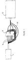
- Figure 1 is a schematic representation of an apparatus 2 in accordance with the present invention.
- a radiation emitting source 4 Radiation from the source is transmitted via fibre-optic bundles 6 to irradiate the interior of an integrating unit 8 .
- the integrating unit can be an integrating cavity or sphere or similar device capable of receiving illumination and causing a high degree of reflection of the radiation within the interior of the unit.
- Fibre-optic bundles 10 received radiation from the interior of the integrating unit and transmit it to a detector 12 .
- the detector can be a spectrograph when radiation source 4 is a broad band light source or, alternatively a photodetector when radiation source 4 is a monochromatic or a tunable laser.
- the photodetector integrates the optical radiation over a specified time and converts the optical signal to a time multiplexed analog electronic signal called a scan where absorbance is calculated.
- the electronic signal is amplified by analog electronic amplifiers and converted to a digital signal by an analog-to-digital converter or ADC.
- the digital information from the converter is interpreted for data analysis by a microprocessor or MP, or other appropriate processor which is in turn connected to a computer.
- the results of the data analysis can be shown on an output device such as a display and on a printer. A user can control the device to specify a particular interferent to be analyzed and to determine the number and timing of measurements.
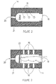
- this integrating unit is an integrating cavity 14 with eight (8) (six ports 16, 18, 20) ports that communicate from the exterior to the interior of the cavity.
- three input ports 16 are illustrated longitudinally linearly located on a first side of cavity 14 .
- Figure 3 which provides a different view of cavity 14 , illustrates a further three entry ports 16 located opposite the three entry ports 16 referred to above in respect of Figure 2 .
- Ports 16 are multiple input ports which accept fibre-optic bundles from the radiation source and thereby provide illumination to the interior of the cavity.
- a port 18 at one end of the cavity is of sufficient circumference to allow insertion of a digit or other target while a port 20 positioned opposite entry port 18 is where fibre-optic bundles receive radiation and transport it to a detector 12.
- the detector can be positioned at the port.
- six (6) entry ports and one (1) exit, or detector port are shown, the number of ports can be increased or decreased (to a minimum of one of each) depending upon the circumstances.
- the surface of the cavity 22 is made of a material capable of efficient back scattering of illumination such as SpectralonTM or other such material and may be a coating or a layer of such material.
- the cavity may contain a support 21 for positioning of the tip of a finger within the cavity (there may be more than one and it may appear differently depending on the target).
- the support is made of, or covered with a material capable of efficient back scattering of illumination such as SpectralonTM or other such material.
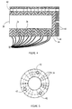
- FIG 4 provides an illustration of another example of integrating unit 8 .
- This unit is an integrating reconfigurable cavity comprised of a multiple "ring" 32 assembly with variable numbers of input ports 34 that communicate from the exterior to the interior of the cavity for entry of input fibres at various directions.
- the port for entry of a digit is 38 and the output port is 40 .
- the embodiment illustrated in Figure 4 consists of 12 "rings" which are held together by a locking pin 42 , and in this embodiment there are three such pins.
- Counting from port 34 the number of input ports, beginning with ring number 3, is 19, followed by a ring with no input ports, which is followed by a ring with 5 input ports followed by a ring with no input ports, which is followed by a ring with 19 input ports, followed by a ring with no input ports, which is followed by a ring with 5 input ports, which is followed by a ring with no input ports which is followed by a ring with 19 input ports, and this is followed by a ring with no input ports, which is followed by a base 44 which contains an exit port 40 .
- the base is removably fixed to an external base 46 which also contains an exit port 40 , and in which the locking pins are fixed.
- the number of rings, the number of entry ports and the number of exit ports as well as their relative positions on the cavity can all be varied, so long as there is at least one port for the sample to enter, one port for light entry and one port for light to exit.
- the rings are made of a material capable of efficient back scattering of illumination such as SpectralonTM or other such material, or the interior of each ring may be covered with a coating or a layer of such material.
- Figure 5 provides a cross sectional view and illustrates the three locking pin sites 42, as well as the exterior to interior input ports 34. While ring-shaped layers are described here, it is understood that any other shape can be used.
- the integrating cavity 60 optionally contains a tube 62 through which the sample fluid 63 flows.
- the cavity may be constructed of layers as is the cavity illustrated in Figure 4 , or it may be, and is preferably of unitary construction as is the cavity illustrated in Figures 2 and 3 .
- the walls of the cavity 64 are made of a material capable of efficient back scattering of illumination such as SpectralonTM or other such material, or the interior of the cavity may be covered with a coating or a layer of such material.
- the radiation source 66 is optically connected to the cavity by fibre optic cables 68 preferably at both ends of the cavity however, input ports can be varied in respect of number of input ports and location along the length of the cavity.
- a photodetector 70 is optically connected to the cavity by fibre optic cables 72 preferably at the centre of the cavity however, output ports can be varied in respect of number of output ports and location along the length of the cavity.
- the input source may be located at the input ports as can the photodetector be located at the output ports.
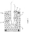
- Figure 7 presents a cross-section of a reconfigurable integrating cavity which has been specifically adapted for a finger sample to be positioned within the cavity.
- the cavity illustrated has multiple input and output ports respectively ( 73 and 74 ) and special features to allow immobilization of a finger in position and to reduce light "leak-out" when finger diameter is significantly less than the diameter of the cavity.
- Collar 75 is made of SpectralonTM, or other such material, and assists in preventing light leakage from the cavity.
- Baffle 76 is also made of SpectralonTM or other such material, and assists in preventing direct light coupling between input and outport ports ( 73 and 74 respectively) as well as assisting in holding the finger in position within the cavity.
- this disclosure relates to a method of measuring the concentration of target substances in the blood or tissue of a patient in a non-invasive way which is not dependent on position of the tissue being analyzed and providing a rapid accurate assessment of the concentration of the target compound. It is further to be understood that this methodology can be adapted to measure light absorption in any sample and is particularly useful in applications where the sample to be analyzed has a complex shape, and/or scatters light and/or is difficult to maintain in a immovable fixed position. It may also be adapted to measure the concentration of target substances in a flowing sample of fluid.
Landscapes
- Health & Medical Sciences (AREA)
- Life Sciences & Earth Sciences (AREA)
- Physics & Mathematics (AREA)
- Pathology (AREA)
- General Health & Medical Sciences (AREA)
- Surgery (AREA)
- Veterinary Medicine (AREA)
- Engineering & Computer Science (AREA)
- Biomedical Technology (AREA)
- Heart & Thoracic Surgery (AREA)
- Medical Informatics (AREA)
- Molecular Biology (AREA)
- Biophysics (AREA)
- Animal Behavior & Ethology (AREA)
- Public Health (AREA)
- Optics & Photonics (AREA)
- Spectroscopy & Molecular Physics (AREA)
- Chemical & Material Sciences (AREA)
- Analytical Chemistry (AREA)
- Biochemistry (AREA)
- General Physics & Mathematics (AREA)
- Immunology (AREA)
- Emergency Medicine (AREA)
- Investigating Or Analysing Materials By Optical Means (AREA)
- Spectrometry And Color Measurement (AREA)
- Optical Measuring Cells (AREA)
Claims (17)
- Vorrichtung zur Messung der Konzentration mindestens einer bekannten Substanz in einer nicht-einheitlichen Probe, wobei die Vorrichtung folgendes aufweist:a. einen nicht-sphärischen Integrationshohlraum (14; 64) mit einem Inneren und einem Äußeren, wobei die Probe im Inneren plaziert wird, wobei der Integrationshohlraum mindestens vier Öffnungen aufweist, die sich vom Äußeren zum Inneren erstrecken;b. eine Strahlungsquelle (4; 66) zum Emittieren eines Strahlungsbündels;c. Mittel (6; 68) zum Übertragen des Strahlungsbündels in das Innere des Hohlraumes durch mindestens zwei der mindestens vier Öffnungen;d. Mittel (10; 72) zum Empfangen von Strahlung aus dem Inneren des Integrationshohlraumes durch mindestens zwei der mindestens vier Öffnungen;e. einen Sensor (12; 70), der optisch mit dem Inneren des Integrationshohlraumes in Verbindung steht, wobei der Sensor auf den Empfang von Strahlung aus dem Inneren des Integrationshohlraumes anspricht;f. Mittel zum Korrelieren eines Sensoransprechens durch den Sensor mit einer Menge an mindestens einer bekannten Substanz in der Probe.
- Vorrichtung nach Anspruch 1, wobei der Integrationshohlraum eine zylindrische Form mit einem offenen Ende und einem geschlossenen Ende aufweist.
- Vorrichtung nach Anspruch 2, wobei der Integrationshohlraum (64) eine Ringstruktur aufweist, wobei die Anzahl an Ringen, Eintrittsöffnungen, Austrittsöffnungen sowie ihre relativen Positionen auf dem Hohlraum variabel sind.
- Vorrichtung nach Anspruch 1, wobei das Innere des Integrationshohlraumes mit einem Material beschichtet ist, welches die Bestrahlung effizient zurückstreuen kann.
- Vorrichtung nach Anspruch 1, wobei das Innere des Integrationshohlraumes aus einem Material hergestellt ist, welches die Bestrahlung effizient zurückstreuen kann.
- Vorrichtung nach Anspruch 3 für die Messung einer Konzentration mindestens einer bekannten Substanz in einem menschlichen Finger, wobei das Innere des Integrationshohlraumes aus einem Material besteht, welches die Bestrahlung effizient zurückstreuen kann, wobei ein Kragen (75), der aus einem Material besteht, welches die Bestrahlung effizient zurückstreuen kann, um das offene Ende teilweise zu bedecken und das Einführen des Fingers in das Innere des Hohlraums zu ermöglichen, eine Blende (76) mit einem Umfang in Kontakt mit den Innenwänden des Hohlraumes, welche den Finger in dem Hohlraum einschließen kann, und Führungsstäbe (77) vorhanden sind, um beim Halten des Fingers in fixierter Position innerhalb des Hohlraumes zu helfen, wobei die mindestens zwei Öffnungen für den Austritt eines Strahlungsbündels oberhalb der Blende gelegen sind und die mindestens zwei Öffnungen für den Eintritt eines Lichtstrahls unterhalb der Blende gelegen sind, wobei die Vorrichtung weiter ein Spektrophotometer aufweist, das optisch mit den Öffnungen gekoppelt ist, um die Strahlungsquelle bereitzustellen und die Absorption von Strahlung durch den Finger zu messen.
- Verfahren zum Messen der Konzentration mindestens einer bekannten Substanz in einer nicht-einheitlichen Probe, wobei das Verfahren die folgenden Schritten aufweist:a. Anordnen der Probe in einem nicht-spärischen Integrationshohlraum (14; 64), welcher ein Inneres und ein Äußeres aufweist, wobei der Integrationshohlraum mindestens vier Öffnungen aufweist, die sich vom Äußeren zum Inneren erstrecken;b. Bereitstellen einer Strahlungsquelle (4; 66) zum Emittieren eines Strahlungsbündels;c. Bereitstellen von Mitteln (6; 68) zum Übertragen des Strahlungsbündels in das Innere des Hohlraumes durch mindestens zwei der mindestens vier Öffnungen;d. Bereitstellen eines Mittels (10; 72) zum Empfangen von Strahlung aus dem Inneren des Integrationshohlraumes durch mindestens zwei der mindestens vier Öffnungen;e. Bereitstellen eines Sensors (12; 70), der optisch mit dem Inneren des Integrationshohlraumes verbunden ist, wobei der Sensor auf den Empfang von Strahlung aus dem Inneren des Integrationshohlraumes reagiert;f. Korrelieren eines Sensoransprechens des Sensors auf eine Menge der mindestens einen bekannten Substanz in der Probe.
- Verfahren nach Anspruch 7, wobei der Integrationshohlraum eine zylindrische Form mit einem offenen Ende und einem geschlossenen Ende aufweist.
- Verfahren nach Anspruch 8, wobei der Integrationshohlraum eine Ringstruktur aufweist, wobei die Anzahl an Ringen, Eintrittsöffnungen, Austrittsöffnungen sowie ihre relativen Positionen auf dem Hohlraum variabel sind.
- Verfahren nach Anspruch 7, wobei das Innere um des Integrationshohlraumes mit einem Material beschichtet ist, welches die Bestrahlung effizient zurückstreuen kann.
- Verfahren nach Anspruch 7, wobei das Innere des Integrationshohlraumes aus einem Material hergestellt ist, welches Bestrahlung effizient zurückstreuen kann.
- Verfahren nach Anspruch 9 für die Messung einer Konzentration mindestens einer bekannten Substanz in einem menschlichen Finger, wobei das Innere des Integrationshohlraumes aus einem Material besteht, welches Bestrahlung effizient zurückstreuen kann, wobei ein Kragen (75) vorhanden ist, welcher aus einem Material besteht, das Strahlung effizient zurückstreuen kann, und welcher einen Eintritt des Fingers in das Innere des Hohlraums ermöglicht, wobei eine Blende (76) vorhanden ist, welche einen Umfang in Kontakt mit den Innenwänden des Hohlraumes aufweist und den Finger im Hohlraum umschließen kann, und wobei Führungsstäbe (77) vorhanden sind, welche helfen, den Finger im Hohlraum in fixierter Position zu halten, wobei die mindestens zwei Öffnungen zum Übertragen des Strahlungsbündels in das Innere des Hohlraums unterhalb der Blende gelegen sind und die mindestens zwei Öffnungen zum Ausgeben des Strahlungsbündels aus dem Inneren des Integrationshohlraumes oberhalb der der Blende gelegen sind; und wobei ein Spektrophotometer, das optisch mit den Öffnungen gekoppelt ist, die Strahlungsquelle bereitstellt und die Absorption von Strahlung durch den Finger misst.
- Verwendung einer spektrophotometrischen Vorrichtung nach den Ansprüchen 1 bis 5 zum Messen einer Konzentration mindesteins einer bekannten Substanz in einer nicht-einheitlichen Probe.
- Verwendung nach Anspruch 13, wobei die Probe ein menschlicher Finger ist und der Integrationshohlraum ein zylindrischer Integrationshohlraum ist, welcher eine Ringstruktur aufweist, wobei die Anzahl an Ringen, Eintrittsöffnungen, Austrittsöffnungen sowie ihre relativen Positionen auf dem Hohlraum variabel sind und wobei der Hohlraum ein offenes Ende, ein geschlossenes Ende, ein Inneres, das aus einem Material besteht, welches Bestrahlung effizient zurückstreuen kann, ein Äußeres, einen Kragen, der aus einem Material besteht, welches Bestrahlung effizient zurückstreuen kann, um das offene Ende teilweise zu bedecken und das Einführen des Fingers in das Innere des Hohlraumes zu ermöglichen, eine Blende mit einem Umfang, der in Kontakt mit den Innenwänden des Hohlraumes steht, die den Finger im Hohlraum umschließen kann, und Führungsstäben zum Unterstützen des Haltens des Fingers in fixierter Position in dem Hohlraum und mehrere Austrittsöffnungen, die sich oberhalb der Blende befinden, und mehrere Eintrittsöffnungen, die sich unterhalb der Blende befinden, aufweist.
- Vorrichtung nach den Ansprüchen 1 und 6, wobei eine der mindestens einen bekannten Substanz Glucose ist.
- Verfahren nach Anspruch 7 und 12, wobei eine der mindestens einen bekannten Substanz Glucose ist.
- Verwendung nach den Ansprüchen 13 und 14, wobei eine der mindestens einen bekannten Substanz Glucose ist.
Applications Claiming Priority (3)
| Application Number | Priority Date | Filing Date | Title |
|---|---|---|---|
| GB9526309 | 1995-12-22 | ||
| GBGB9526309.1A GB9526309D0 (en) | 1995-12-22 | 1995-12-22 | Integrating cavity for spectroscopic measurement in light scattering samples |
| PCT/CA1996/000856 WO1997023159A1 (en) | 1995-12-22 | 1996-12-20 | Integrating cavity for spectroscopic measurement in light scattering samples |
Publications (2)
| Publication Number | Publication Date |
|---|---|
| EP1076509A1 EP1076509A1 (de) | 2001-02-21 |
| EP1076509B1 true EP1076509B1 (de) | 2004-09-22 |
Family
ID=10785914
Family Applications (1)
| Application Number | Title | Priority Date | Filing Date |
|---|---|---|---|
| EP96941550A Expired - Lifetime EP1076509B1 (de) | 1995-12-22 | 1996-12-20 | Spektroskopische messungen an lichtstreuendem prüfgut mittels integrations -hohlraum |
Country Status (5)
| Country | Link |
|---|---|
| EP (1) | EP1076509B1 (de) |
| AT (1) | ATE276700T1 (de) |
| DE (1) | DE69633468T2 (de) |
| GB (1) | GB9526309D0 (de) |
| WO (1) | WO1997023159A1 (de) |
Cited By (1)
| Publication number | Priority date | Publication date | Assignee | Title |
|---|---|---|---|---|
| WO2015043049A1 (zh) * | 2013-09-30 | 2015-04-02 | 江苏英诺华医疗技术有限公司 | 一种多功能医用分析仪 |
Families Citing this family (24)
| Publication number | Priority date | Publication date | Assignee | Title |
|---|---|---|---|---|
| US6580086B1 (en) | 1999-08-26 | 2003-06-17 | Masimo Corporation | Shielded optical probe and method |
| JP3758823B2 (ja) * | 1997-08-06 | 2006-03-22 | 倉敷紡績株式会社 | 生体の位置決め装置 |
| US7890158B2 (en) | 2001-06-05 | 2011-02-15 | Lumidigm, Inc. | Apparatus and method of biometric determination using specialized optical spectroscopy systems |
| SE512047C2 (sv) * | 1998-03-02 | 2000-01-17 | John Jacob Engellau | Mätanordning, särskilt för blodsockerbestämning |
| US6515273B2 (en) | 1999-08-26 | 2003-02-04 | Masimo Corporation | System for indicating the expiration of the useful operating life of a pulse oximetry sensor |
| US6816605B2 (en) | 1999-10-08 | 2004-11-09 | Lumidigm, Inc. | Methods and systems for biometric identification of individuals using linear optical spectroscopy |
| US6542764B1 (en) | 1999-12-01 | 2003-04-01 | Masimo Corporation | Pulse oximeter monitor for expressing the urgency of the patient's condition |
| US6865408B1 (en) | 2001-04-11 | 2005-03-08 | Inlight Solutions, Inc. | System for non-invasive measurement of glucose in humans |
| US6983176B2 (en) | 2001-04-11 | 2006-01-03 | Rio Grande Medical Technologies, Inc. | Optically similar reference samples and related methods for multivariate calibration models used in optical spectroscopy |
| US7043288B2 (en) | 2002-04-04 | 2006-05-09 | Inlight Solutions, Inc. | Apparatus and method for spectroscopic analysis of tissue to detect diabetes in an individual |
| US7126682B2 (en) | 2001-04-11 | 2006-10-24 | Rio Grande Medical Technologies, Inc. | Encoded variable filter spectrometer |
| US6862091B2 (en) | 2001-04-11 | 2005-03-01 | Inlight Solutions, Inc. | Illumination device and method for spectroscopic analysis |
| US6975891B2 (en) * | 2001-12-21 | 2005-12-13 | Nir Diagnostics Inc. | Raman spectroscopic system with integrating cavity |
| US7027848B2 (en) | 2002-04-04 | 2006-04-11 | Inlight Solutions, Inc. | Apparatus and method for non-invasive spectroscopic measurement of analytes in tissue using a matched reference analyte |
| US7620212B1 (en) | 2002-08-13 | 2009-11-17 | Lumidigm, Inc. | Electro-optical sensor |
| WO2004046709A1 (de) * | 2002-11-20 | 2004-06-03 | Richard Fritz Sauter | Analyseverfahren für moleküle, zur sequenzierung von molekülen und spektrometer hierfür |
| US20050073690A1 (en) * | 2003-10-03 | 2005-04-07 | Abbink Russell E. | Optical spectroscopy incorporating a vertical cavity surface emitting laser (VCSEL) |
| US10188348B2 (en) | 2006-06-05 | 2019-01-29 | Masimo Corporation | Parameter upgrade system |
| US7880626B2 (en) | 2006-10-12 | 2011-02-01 | Masimo Corporation | System and method for monitoring the life of a physiological sensor |
| US8571619B2 (en) | 2009-05-20 | 2013-10-29 | Masimo Corporation | Hemoglobin display and patient treatment |
| DE102010001189B4 (de) | 2010-01-25 | 2021-08-19 | BAM Bundesanstalt für Materialforschung und -prüfung | Vorrichtung und Verfahren zur Bestimmung der Photolumineszenzquantenausbeute und weiterer optischer Eigenschaften einer Probe |
| DE102010048101A1 (de) * | 2010-01-25 | 2011-07-28 | Krieg, Gunther, Prof. Dr.-Ing., 76227 | Verfahren und Vorrichtung zur Detektion und Aussortierung optisch inaktiver Substanzen |
| DE102010041749A1 (de) * | 2010-09-30 | 2012-04-05 | Carl Zeiss Microlmaging Gmbh | Messeinrichtungen und Vorrichtungen zur spektroskopischen Untersuchung von Proben |
| WO2018070882A1 (en) | 2016-10-11 | 2018-04-19 | Darby Brendan Liam | A spectrometer apparatus for measuring spectra of a liquid sample using an integrating cavity |
Family Cites Families (4)
| Publication number | Priority date | Publication date | Assignee | Title |
|---|---|---|---|---|
| GB8515132D0 (en) * | 1985-06-14 | 1985-07-17 | British Nuclear Fuels Plc | Measuring photosynthetic activities of plants |
| US4867559A (en) * | 1988-01-06 | 1989-09-19 | Amoco Corporation | Liquid/liquid fiber-optic fluorescence detector and absorbance analyzer |
| US5402778A (en) * | 1993-01-19 | 1995-04-04 | Nim Incorporated | Spectrophotometric examination of tissue of small dimension |
| US5372136A (en) * | 1990-10-06 | 1994-12-13 | Noninvasive Medical Technology Corporation | System and method for noninvasive hematocrit monitoring |
-
1995
- 1995-12-22 GB GBGB9526309.1A patent/GB9526309D0/en active Pending
-
1996
- 1996-12-20 WO PCT/CA1996/000856 patent/WO1997023159A1/en not_active Ceased
- 1996-12-20 DE DE69633468T patent/DE69633468T2/de not_active Expired - Lifetime
- 1996-12-20 AT AT96941550T patent/ATE276700T1/de not_active IP Right Cessation
- 1996-12-20 EP EP96941550A patent/EP1076509B1/de not_active Expired - Lifetime
Cited By (1)
| Publication number | Priority date | Publication date | Assignee | Title |
|---|---|---|---|---|
| WO2015043049A1 (zh) * | 2013-09-30 | 2015-04-02 | 江苏英诺华医疗技术有限公司 | 一种多功能医用分析仪 |
Also Published As
| Publication number | Publication date |
|---|---|
| WO1997023159A1 (en) | 1997-07-03 |
| ATE276700T1 (de) | 2004-10-15 |
| DE69633468D1 (de) | 2004-10-28 |
| EP1076509A1 (de) | 2001-02-21 |
| GB9526309D0 (en) | 1996-02-21 |
| DE69633468T2 (de) | 2005-12-15 |
Similar Documents
| Publication | Publication Date | Title |
|---|---|---|
| EP1076509A1 (de) | Spektrographische messungen an lichtstrevenden prüfgut mittels integrations -hohlraum | |
| US5596987A (en) | Optical coupler for in vivo examination of biological tissue | |
| US5692504A (en) | Method and apparatus for the analysis of glucose in a biological matrix | |
| Peterson et al. | Fiber-optic sensors for biomedical applications | |
| US6219566B1 (en) | Method of measuring concentration of luminescent materials in turbid media | |
| US6614521B2 (en) | Device for verifying the accuracy of a spectral analyzer | |
| US7277740B2 (en) | Analysis system for reagent-free determination of the concentration of an analyte in living tissue | |
| US6103197A (en) | Method and apparatus for optically determining total hemoglobin concentration | |
| JPH08509287A (ja) | 小寸法の組織の分光光度測定検査 | |
| EP0948284B1 (de) | Überwachung von gewebe-bestandteilen mittels infrarot-strahlung | |
| US6678541B1 (en) | Optical fiber probe and methods for measuring optical properties | |
| US6741875B1 (en) | Method for determination of analytes using near infrared, adjacent visible spectrum and an array of longer near infrared wavelengths | |
| US6694157B1 (en) | Method and apparatus for determination of pH pCO2, hemoglobin, and hemoglobin oxygen saturation | |
| US7304724B2 (en) | Method and apparatus for quantification of optical properties of superficial volumes | |
| CA2383727A1 (en) | Method for determination of analytes using near infrared, adjacent visible spectrum and an array of longer near infrared wavelengths | |
| US20030120137A1 (en) | Raman spectroscopic system with integrating cavity | |
| JP2005513491A (ja) | 生物学的マトリックス中の光輸送パラメータおよび分析物の決定のための方法および装置 | |
| KR20030004450A (ko) | 저 투과율 샘플의 분석물 검출에 사용하기 위한 이중빔푸리에 변환 적외선 방법 및 장치 | |
| US20110118570A1 (en) | Optic sensor device with sers | |
| JPH037370B2 (de) | ||
| JPH10500338A (ja) | バイオロジカル・サンプル中の分析物を決定するための方法および装置 | |
| Johnston et al. | Performance comparison between high and low resolution spectrophotometers used in a white light surface plasmon resonance sensor | |
| EP0032774A2 (de) | Optische Reflektionsmesseinrichtung | |
| CA2540110A1 (en) | Method and apparatus for backscatter spectroscopy | |
| US20040141179A1 (en) | Apparatus and method for direct measurement of absorption and scattering coefficients in situ |
Legal Events
| Date | Code | Title | Description |
|---|---|---|---|
| PUAI | Public reference made under article 153(3) epc to a published international application that has entered the european phase |
Free format text: ORIGINAL CODE: 0009012 |
|
| 17P | Request for examination filed |
Effective date: 19990722 |
|
| AK | Designated contracting states |
Kind code of ref document: A1 Designated state(s): AT BE CH DE DK ES FI FR GB GR IE IT LI LU MC NL PT SE |
|
| 17Q | First examination report despatched |
Effective date: 20030128 |
|
| GRAP | Despatch of communication of intention to grant a patent |
Free format text: ORIGINAL CODE: EPIDOSNIGR1 |
|
| GRAS | Grant fee paid |
Free format text: ORIGINAL CODE: EPIDOSNIGR3 |
|
| GRAA | (expected) grant |
Free format text: ORIGINAL CODE: 0009210 |
|
| AK | Designated contracting states |
Kind code of ref document: B1 Designated state(s): AT BE CH DE DK ES FI FR GB GR IE IT LI LU MC NL PT SE |
|
| PG25 | Lapsed in a contracting state [announced via postgrant information from national office to epo] |
Ref country code: NL Free format text: LAPSE BECAUSE OF FAILURE TO SUBMIT A TRANSLATION OF THE DESCRIPTION OR TO PAY THE FEE WITHIN THE PRESCRIBED TIME-LIMIT Effective date: 20040922 Ref country code: LI Free format text: LAPSE BECAUSE OF FAILURE TO SUBMIT A TRANSLATION OF THE DESCRIPTION OR TO PAY THE FEE WITHIN THE PRESCRIBED TIME-LIMIT Effective date: 20040922 Ref country code: IT Free format text: LAPSE BECAUSE OF FAILURE TO SUBMIT A TRANSLATION OF THE DESCRIPTION OR TO PAY THE FEE WITHIN THE PRE;WARNING: LAPSES OF ITALIAN PATENTS WITH EFFECTIVE DATE BEFORE 2007 MAY HAVE OCCURRED AT ANY TIME BEFORE 2007. THE CORRECT EFFECTIVE DATE MAY BE DIFFERENT FROM THE ONE RECORDED.SCRIBED TIME-LIMIT Effective date: 20040922 Ref country code: FI Free format text: LAPSE BECAUSE OF FAILURE TO SUBMIT A TRANSLATION OF THE DESCRIPTION OR TO PAY THE FEE WITHIN THE PRESCRIBED TIME-LIMIT Effective date: 20040922 Ref country code: ES Free format text: LAPSE BECAUSE OF FAILURE TO SUBMIT A TRANSLATION OF THE DESCRIPTION OR TO PAY THE FEE WITHIN THE PRESCRIBED TIME-LIMIT Effective date: 20040922 Ref country code: CH Free format text: LAPSE BECAUSE OF FAILURE TO SUBMIT A TRANSLATION OF THE DESCRIPTION OR TO PAY THE FEE WITHIN THE PRESCRIBED TIME-LIMIT Effective date: 20040922 Ref country code: BE Free format text: LAPSE BECAUSE OF FAILURE TO SUBMIT A TRANSLATION OF THE DESCRIPTION OR TO PAY THE FEE WITHIN THE PRESCRIBED TIME-LIMIT Effective date: 20040922 Ref country code: AT Free format text: LAPSE BECAUSE OF FAILURE TO SUBMIT A TRANSLATION OF THE DESCRIPTION OR TO PAY THE FEE WITHIN THE PRESCRIBED TIME-LIMIT Effective date: 20040922 |
|
| REG | Reference to a national code |
Ref country code: GB Ref legal event code: FG4D |
|
| REG | Reference to a national code |
Ref country code: CH Ref legal event code: EP |
|
| REG | Reference to a national code |
Ref country code: IE Ref legal event code: FG4D |
|
| REF | Corresponds to: |
Ref document number: 69633468 Country of ref document: DE Date of ref document: 20041028 Kind code of ref document: P |
|
| PG25 | Lapsed in a contracting state [announced via postgrant information from national office to epo] |
Ref country code: LU Free format text: LAPSE BECAUSE OF NON-PAYMENT OF DUE FEES Effective date: 20041220 Ref country code: IE Free format text: LAPSE BECAUSE OF NON-PAYMENT OF DUE FEES Effective date: 20041220 |
|
| PG25 | Lapsed in a contracting state [announced via postgrant information from national office to epo] |
Ref country code: SE Free format text: LAPSE BECAUSE OF FAILURE TO SUBMIT A TRANSLATION OF THE DESCRIPTION OR TO PAY THE FEE WITHIN THE PRESCRIBED TIME-LIMIT Effective date: 20041222 Ref country code: GR Free format text: LAPSE BECAUSE OF FAILURE TO SUBMIT A TRANSLATION OF THE DESCRIPTION OR TO PAY THE FEE WITHIN THE PRESCRIBED TIME-LIMIT Effective date: 20041222 Ref country code: DK Free format text: LAPSE BECAUSE OF FAILURE TO SUBMIT A TRANSLATION OF THE DESCRIPTION OR TO PAY THE FEE WITHIN THE PRESCRIBED TIME-LIMIT Effective date: 20041222 |
|
| PG25 | Lapsed in a contracting state [announced via postgrant information from national office to epo] |
Ref country code: MC Free format text: LAPSE BECAUSE OF NON-PAYMENT OF DUE FEES Effective date: 20041231 |
|
| RAP2 | Party data changed (patent owner data changed or rights of a patent transferred) |
Owner name: NIR DIAGNOSTICS INC. |
|
| REG | Reference to a national code |
Ref country code: CH Ref legal event code: PL |
|
| NLV1 | Nl: lapsed or annulled due to failure to fulfill the requirements of art. 29p and 29m of the patents act | ||
| PLBE | No opposition filed within time limit |
Free format text: ORIGINAL CODE: 0009261 |
|
| STAA | Information on the status of an ep patent application or granted ep patent |
Free format text: STATUS: NO OPPOSITION FILED WITHIN TIME LIMIT |
|
| REG | Reference to a national code |
Ref country code: FR Ref legal event code: CD |
|
| ET | Fr: translation filed | ||
| 26N | No opposition filed |
Effective date: 20050623 |
|
| REG | Reference to a national code |
Ref country code: IE Ref legal event code: MM4A |
|
| PG25 | Lapsed in a contracting state [announced via postgrant information from national office to epo] |
Ref country code: PT Free format text: LAPSE BECAUSE OF NON-PAYMENT OF DUE FEES Effective date: 20050222 |
|
| PGFP | Annual fee paid to national office [announced via postgrant information from national office to epo] |
Ref country code: FR Payment date: 20110110 Year of fee payment: 15 |
|
| PGFP | Annual fee paid to national office [announced via postgrant information from national office to epo] |
Ref country code: GB Payment date: 20101222 Year of fee payment: 15 |
|
| PGFP | Annual fee paid to national office [announced via postgrant information from national office to epo] |
Ref country code: DE Payment date: 20110127 Year of fee payment: 15 |
|
| GBPC | Gb: european patent ceased through non-payment of renewal fee |
Effective date: 20111220 |
|
| REG | Reference to a national code |
Ref country code: FR Ref legal event code: ST Effective date: 20120831 |
|
| REG | Reference to a national code |
Ref country code: DE Ref legal event code: R119 Ref document number: 69633468 Country of ref document: DE Effective date: 20120703 |
|
| PG25 | Lapsed in a contracting state [announced via postgrant information from national office to epo] |
Ref country code: DE Free format text: LAPSE BECAUSE OF NON-PAYMENT OF DUE FEES Effective date: 20120703 Ref country code: GB Free format text: LAPSE BECAUSE OF NON-PAYMENT OF DUE FEES Effective date: 20111220 |
|
| PG25 | Lapsed in a contracting state [announced via postgrant information from national office to epo] |
Ref country code: FR Free format text: LAPSE BECAUSE OF NON-PAYMENT OF DUE FEES Effective date: 20120102 |