EP1076606B1 - Verfahren und gerät zur herstellung einer kunststofffolie, und kunststofffolie - Google Patents
Verfahren und gerät zur herstellung einer kunststofffolie, und kunststofffolie Download PDFInfo
- Publication number
- EP1076606B1 EP1076606B1 EP99914580A EP99914580A EP1076606B1 EP 1076606 B1 EP1076606 B1 EP 1076606B1 EP 99914580 A EP99914580 A EP 99914580A EP 99914580 A EP99914580 A EP 99914580A EP 1076606 B1 EP1076606 B1 EP 1076606B1
- Authority
- EP
- European Patent Office
- Prior art keywords
- plastic film
- orientation
- plastic
- gas
- bubbles
- Prior art date
- Legal status (The legal status is an assumption and is not a legal conclusion. Google has not performed a legal analysis and makes no representation as to the accuracy of the status listed.)
- Expired - Lifetime
Links
Images


Classifications
-
- B—PERFORMING OPERATIONS; TRANSPORTING
- B29—WORKING OF PLASTICS; WORKING OF SUBSTANCES IN A PLASTIC STATE IN GENERAL
- B29C—SHAPING OR JOINING OF PLASTICS; SHAPING OF MATERIAL IN A PLASTIC STATE, NOT OTHERWISE PROVIDED FOR; AFTER-TREATMENT OF THE SHAPED PRODUCTS, e.g. REPAIRING
- B29C48/00—Extrusion moulding, i.e. expressing the moulding material through a die or nozzle which imparts the desired form; Apparatus therefor
- B29C48/25—Component parts, details or accessories; Auxiliary operations
- B29C48/88—Thermal treatment of the stream of extruded material, e.g. cooling
- B29C48/90—Thermal treatment of the stream of extruded material, e.g. cooling with calibration or sizing, i.e. combined with fixing or setting of the final dimensions of the extruded article
-
- B—PERFORMING OPERATIONS; TRANSPORTING
- B29—WORKING OF PLASTICS; WORKING OF SUBSTANCES IN A PLASTIC STATE IN GENERAL
- B29C—SHAPING OR JOINING OF PLASTICS; SHAPING OF MATERIAL IN A PLASTIC STATE, NOT OTHERWISE PROVIDED FOR; AFTER-TREATMENT OF THE SHAPED PRODUCTS, e.g. REPAIRING
- B29C48/00—Extrusion moulding, i.e. expressing the moulding material through a die or nozzle which imparts the desired form; Apparatus therefor
- B29C48/001—Combinations of extrusion moulding with other shaping operations
- B29C48/0018—Combinations of extrusion moulding with other shaping operations combined with shaping by orienting, stretching or shrinking, e.g. film blowing
-
- B—PERFORMING OPERATIONS; TRANSPORTING
- B29—WORKING OF PLASTICS; WORKING OF SUBSTANCES IN A PLASTIC STATE IN GENERAL
- B29C—SHAPING OR JOINING OF PLASTICS; SHAPING OF MATERIAL IN A PLASTIC STATE, NOT OTHERWISE PROVIDED FOR; AFTER-TREATMENT OF THE SHAPED PRODUCTS, e.g. REPAIRING
- B29C48/00—Extrusion moulding, i.e. expressing the moulding material through a die or nozzle which imparts the desired form; Apparatus therefor
- B29C48/03—Extrusion moulding, i.e. expressing the moulding material through a die or nozzle which imparts the desired form; Apparatus therefor characterised by the shape of the extruded material at extrusion
- B29C48/07—Flat, e.g. panels
- B29C48/08—Flat, e.g. panels flexible, e.g. films
-
- B—PERFORMING OPERATIONS; TRANSPORTING
- B29—WORKING OF PLASTICS; WORKING OF SUBSTANCES IN A PLASTIC STATE IN GENERAL
- B29C—SHAPING OR JOINING OF PLASTICS; SHAPING OF MATERIAL IN A PLASTIC STATE, NOT OTHERWISE PROVIDED FOR; AFTER-TREATMENT OF THE SHAPED PRODUCTS, e.g. REPAIRING
- B29C48/00—Extrusion moulding, i.e. expressing the moulding material through a die or nozzle which imparts the desired form; Apparatus therefor
- B29C48/25—Component parts, details or accessories; Auxiliary operations
- B29C48/30—Extrusion nozzles or dies
- B29C48/305—Extrusion nozzles or dies having a wide opening, e.g. for forming sheets
-
- B—PERFORMING OPERATIONS; TRANSPORTING
- B29—WORKING OF PLASTICS; WORKING OF SUBSTANCES IN A PLASTIC STATE IN GENERAL
- B29C—SHAPING OR JOINING OF PLASTICS; SHAPING OF MATERIAL IN A PLASTIC STATE, NOT OTHERWISE PROVIDED FOR; AFTER-TREATMENT OF THE SHAPED PRODUCTS, e.g. REPAIRING
- B29C48/00—Extrusion moulding, i.e. expressing the moulding material through a die or nozzle which imparts the desired form; Apparatus therefor
- B29C48/25—Component parts, details or accessories; Auxiliary operations
- B29C48/36—Means for plasticising or homogenising the moulding material or forcing it through the nozzle or die
- B29C48/361—Means for plasticising or homogenising the moulding material or forcing it through the nozzle or die with the barrel or with a part thereof rotating
-
- B—PERFORMING OPERATIONS; TRANSPORTING
- B29—WORKING OF PLASTICS; WORKING OF SUBSTANCES IN A PLASTIC STATE IN GENERAL
- B29C—SHAPING OR JOINING OF PLASTICS; SHAPING OF MATERIAL IN A PLASTIC STATE, NOT OTHERWISE PROVIDED FOR; AFTER-TREATMENT OF THE SHAPED PRODUCTS, e.g. REPAIRING
- B29C48/00—Extrusion moulding, i.e. expressing the moulding material through a die or nozzle which imparts the desired form; Apparatus therefor
- B29C48/25—Component parts, details or accessories; Auxiliary operations
- B29C48/36—Means for plasticising or homogenising the moulding material or forcing it through the nozzle or die
- B29C48/465—Means for plasticising or homogenising the moulding material or forcing it through the nozzle or die using rollers
-
- B—PERFORMING OPERATIONS; TRANSPORTING
- B29—WORKING OF PLASTICS; WORKING OF SUBSTANCES IN A PLASTIC STATE IN GENERAL
- B29C—SHAPING OR JOINING OF PLASTICS; SHAPING OF MATERIAL IN A PLASTIC STATE, NOT OTHERWISE PROVIDED FOR; AFTER-TREATMENT OF THE SHAPED PRODUCTS, e.g. REPAIRING
- B29C48/00—Extrusion moulding, i.e. expressing the moulding material through a die or nozzle which imparts the desired form; Apparatus therefor
- B29C48/25—Component parts, details or accessories; Auxiliary operations
- B29C48/88—Thermal treatment of the stream of extruded material, e.g. cooling
- B29C48/91—Heating, e.g. for cross linking
-
- B—PERFORMING OPERATIONS; TRANSPORTING
- B29—WORKING OF PLASTICS; WORKING OF SUBSTANCES IN A PLASTIC STATE IN GENERAL
- B29C—SHAPING OR JOINING OF PLASTICS; SHAPING OF MATERIAL IN A PLASTIC STATE, NOT OTHERWISE PROVIDED FOR; AFTER-TREATMENT OF THE SHAPED PRODUCTS, e.g. REPAIRING
- B29C48/00—Extrusion moulding, i.e. expressing the moulding material through a die or nozzle which imparts the desired form; Apparatus therefor
- B29C48/25—Component parts, details or accessories; Auxiliary operations
- B29C48/88—Thermal treatment of the stream of extruded material, e.g. cooling
- B29C48/911—Cooling
- B29C48/9135—Cooling of flat articles, e.g. using specially adapted supporting means
- B29C48/914—Cooling drums
-
- B—PERFORMING OPERATIONS; TRANSPORTING
- B29—WORKING OF PLASTICS; WORKING OF SUBSTANCES IN A PLASTIC STATE IN GENERAL
- B29C—SHAPING OR JOINING OF PLASTICS; SHAPING OF MATERIAL IN A PLASTIC STATE, NOT OTHERWISE PROVIDED FOR; AFTER-TREATMENT OF THE SHAPED PRODUCTS, e.g. REPAIRING
- B29C48/00—Extrusion moulding, i.e. expressing the moulding material through a die or nozzle which imparts the desired form; Apparatus therefor
- B29C48/25—Component parts, details or accessories; Auxiliary operations
- B29C48/88—Thermal treatment of the stream of extruded material, e.g. cooling
- B29C48/919—Thermal treatment of the stream of extruded material, e.g. cooling using a bath, e.g. extruding into an open bath to coagulate or cool the material
Definitions
- the invention relates to a method for making a plastic film, the method comprising extruding a plastic film and orientating it.
- the invention also relates to an apparatus for making a plastic film, the apparatus comprising an extruder and at least one orientation device for orientating the extruded film.
- the invention further relates to a plastic film which comprises bubbles with the maximum diameter of about 100 micrometers and the maximum height of about 10 micrometers.
- EP publication 0,182,764 discloses a thin polypropylene film which contains wide and flat disk-like bubbles, which are about 80 micrometers in length and about 50 micrometers in width.
- the film is produced by extruding material which has been foamed chemically or by means of gas and by orientating the extruded material biaxially. The result is a very versatile plastic film.
- the foaming degree of the film is less than 50%, which is why the properties of the film are not good enough for all purposes.
- the object of this invention is to provide a very good and thin foamed plastic film and a simple and reliable method and apparatus for making said plastic film.
- the method of the invention is characterized in that before extrusion material is mixed into the plastic of the plastic film, cavitation bubbles are formed in the plastic film to be stretched due to the influence of the material, after extrusion the plastic film is orientated by stretching, and simultaneously with orientation pressurized gas is arranged to act on the plastic film so that the gas diffuses in the cavitation bubbles, and thus bubbles containing gas are formed in the plastic film.
- the apparatus of the invention is characterized in that the apparatus comprises gas supply means arranged in one orientation device for feeding pressurized gas into the plastic film simultaneously with orientation by stretching so that the fed gas diffuses in the cavitation bubbles that are formed in the plastic film during stretching, and thus bubbles containing gas are formed in the plastic film.
- the plastic film of the invention is characterized in that material is mixed into the plastic of the plastic film, cavitation bubbles are formed in the plastic film to be stretched due to the influence of the material, and the plastic film is subjected to stretching and to pressure of pressurized gas simultaneously with stretching so that the bubbles contain said gas, the foaming degree of the plastic film being over 70%.
- the basic idea of the invention is that a film is extruded from plastic material by means of an extruder and material has been mixed into the plastic so that when the plastic is stretched, cavitation bubbles are formed in the material particles mixed into the plastic.
- the film is orientated by stretching and at the same time gas is fed into the film under high pressure so that the gas diffuses in the cavitation bubbles and causes overpressure in them.
- the idea of a preferred embodiment is that after the first orientation the plastic film is orientated by stretching it in the direction substantially perpendicular to the first orientation direction, and thus the overpressure is released in the cavitation bubbles and the bubbles expand.
- An advantage of the invention is that very thin films with a foaming degree of about 70 to 90% can be provided in a relatively simple manner.
- An advantage of the high foaming degree is that the electric and mechanical properties of the film are very good.
- a further advantage is that the method and apparatus can be used for making a film for example of polymethylpentene or cyclic olefin copolymer.
- FIG. 1 is a side view of an apparatus according to the invention.
- the apparatus comprises an extruder 1.
- the extruder may be for example conical, i.e. it comprises a cone-shaped rotor 2, outside of which there is an outer stator 3 whose surface at least on the rotor 2 side is cone-shaped, and inside the rotor there is an inner stator 4 whose surface at least on the rotor 2 side is cone-shaped.
- the rotor 2 rotates, it extrudes material which is between the rotor 2 and the stators 3 and 4 from the extruder 1 in a manner known per se.
- the figures do not illustrate e.g.
- the extruder 1 may comprise more than one rotor 2 and more than two stators 3 and 4. In that case the extruder 1 can be used for extruding multilayer products.
- the solution with one rotor 2 and two stators 3 and 4 can be used for making two-layer products.
- the end portion of the inner stator 4 is wide and tapers in the vertical direction so that together with the nozzle 6 it forms a relatively flat and wide gap through which the plastic 5a is extruded. After the nozzle 6 there is a calibration piece 7 whose nuts are used for adjusting the height of the gap, which allows to define the thickness of the plastic film 5 to be obtained from the extruder 1.
- the cooling device 8 may comprise e.g. a cooling roll 9, which is arranged in a cooling tank 10 containing a cooling medium, e.g. water.
- the plastic film 5 is arranged to be pressed against the cooling roll 9.
- the apparatus according to Figure 1 uses auxiliary rolls 11 for guiding the plastic film 5 at several points.
- the machine direction orientation device 12 comprises orientation rolls 13 whose velocities are adjusted so that they can be used for stretching the plastic film 5 and thus for orientation in the machine direction. If desired, the velocity of each orientation roll 13 can be adjusted separately.
- the machine direction orientation device 12 may also comprise heating means 14, such as radiation heaters, for heating the plastic film 5 in a manner known per se.
- the orientation rolls 13 can also be used for heating the plastic film by supplying a heating medium, such as heated oil, to the orientation rolls 13 so that the orientation rolls 13 become warm. If desired, the temperature of each orientation roll 13 can be adjusted separately.
- the orientation rolls are arranged in a discharge chamber 15.
- Pressurized gas preferably air
- nitrogen or another gas or gas mixture for instance, may be used as the gas to be fed.
- the gas to be fed may also be selected according to the desired electric properties. For example, in respect of the dielectric strength of the product it would be advisable to use sulphurhexafluoride SF 6 and in respect of chargeability e.g. argon.
- the pressure of the gas to be fed is relatively small compared to the typical foaming methods, being preferably about 10 bars, but it may vary between 3 and 20 bars, for instance.
- Suitable material such as calcium carbonate particles, is mixed into the plastic 5a of the plastic film 5, and due to the influence of the particles the joint surfaces of the plastic molecules and the mixed material are torn during orientation, and thus cavitation bubbles are formed.
- orientation is performed by arranging pressurized gas to act on the plastic film 5, the gas in question diffuses in the cavitation bubbles and causes overpressure in the bubbles.
- the pressurized gas can act on both sides of the plastic film 5, and thus gas bubbles are formed evenly in the plastic film 5.
- the discharge chamber 15 is sealed at the entry and exit of the plastic film 5 in a manner known per se.
- the plastic film 5 is supplied to a cross-direction orientation device 17.
- the plastic film 5 is stretched in the cross-direction, i.e. orientation is performed in the direction substantially perpendicular to the direction of the orientation performed in the machine direction device 12. Due to the overpressure of the gas in the bubbles and cross-direction stretching the bubbles can grow sideways and also to some extent in the vertical direction in the cross-direction orientation device 17.
- the foaming degree of the film is for example about 70 to 90%. The foaming degree can be adjusted simply by adjusting the pressure of the gas to be fed into the discharge chamber 15.
- the cross-direction orientation device 17 comprises two orientation wheels 18, and an orientation band 19 is arranged against both of the wheels.
- the orientation band 19 is an endless band which is guided by means of band guide rolls 20.
- the orientation band 19 presses the edges of the plastic film 5 firmly and evenly between the orientation wheel 18 and the orientation band 19 substantially along the whole travel the cross-direction orientation device 17, in which case the film is not subjected to varying pressure stress or tensile strain, and thus the plastic film stretches sideways without tearing.
- Figure 1 the plastic film 5, orientation wheel 18 and orientation band 19 are illustrated at a distance from one another for the sake of clarity, but in reality these parts are pressed firmly against one another.
- the orientation wheels 18 and the orientation bands 19 are arranged so that in the direction of the plastic film they are further away from one another at the end than at the beginning, as is illustrated in Figure 2, and thus the cross-direction orientation device 17 stretches and simultaneously orientates the plastic film 5 in the cross-direction.
- the deviation of the angle between the orientation wheels 18 and the orientation bands 19 from the machine direction can be adjusted according to the desired degree of cross-direction stretching.
- One or more band guide rolls 20 can be arranged to be rotated by the rotating means. Since the bands 19 are firmly pressed against the orientation wheels 18, the orientation wheels 18 do not necessarily need rotating means but may rotate freely. For the sake of clarity the enclosed figures do not illustrate rotating means or other actuators of the apparatus.
- a curved support plate 21, which has substantially the same shape as the circumference of the orientation wheels 18, is arranged between the orientation wheels 18 to support the plastic film 5.
- the cross-direction orientation device 17 can be placed in a casing 26 of its own. If desired, the casing 26 can be provided with heaters known per se, such as radiation heaters, to heat the plastic film 5.
- the plastic film 5 is led to a relaxation unit 22.
- the relaxation unit 22 the plastic film 5 is relaxed, and thus the plastic film shrinks a bit in a manner known per se. Finally, the plastic film 5 is wound on a reel 23.
- Figure 2 is a cross-sectional top view of the apparatus of the invention at the extruder 1.
- Figure 2 does not illustrate the plastic film 5 or the support structures of the apparatus onto which the rolls, reels and plates of the apparatus are attached, for instance.
- Figure 3 is a cross-sectional view of a detail of the extruder 1 along line A-A of Figure 1.
- both the outer stator and the inner stator 4 are round in cross-section.
- the plastic material 5a is also in an annular feeding channel.
- Figure 4 is a cross-sectional view of a detail of the extruder 1 along line B-B of Figure 1.
- the wide tip of the inner stator 4 and the shape of the nozzle 6 which extrude the plastic 5a into the wide and flat gap, and thus a flat plastic film 5 is formed from the plastic 5a.
- Figure 5 is a cross-sectional view of a detail of the cross-direction orientation device 17 along line C-C of Figure 1. It is seen in Figure 5 how the orientation wheel and the orientation band are pushed against each other and press the plastic film 5 between each other.
- the surface of the support plate 21 against the plastic film 5 may be heated e.g. by providing it with heating resistors, and thus the plastic film 5 slides along the sliding surface in question very easily.
- propellant such as air
- the gas in question may be heated, if desired, and thus the sliding surface of the support plate 21 and the plastic film 5 are heated with the propellant flowing through the gaps 21a.
- Figure 6 illustrates an extruder 1 used in the apparatus according to the invention.
- the nozzle 6 of the extruder 1 widens up to the end portion of the extruder, i.e. up to the point where the plastic film 5 exits from the extruder 1.
- the plastic 5a is thus all the time subjected to cross-direction orientation in addition to longitudinal orientation, which makes it considerably easier to orientate the plastic film in the cross-direction at a later processing stage.
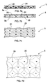
- Figure 7a is a side view of the plastic film 5.
- calcium carbonate particles 24 have been mixed into the plastic 5a.
- some other material may also be mixed into the plastic 5a.
- the material should be such that it causes the joint surface of the plastic molecules and the material mixed into the plastic 5a to tear when the plastic film 5 is stretched so that cavitation bubbles are formed where the joint surfaces are torn.
- some oily substance such as silicone oil or paraffin oil, can be mixed into the plastic 5a.
- the particles mixed into the plastic 5a may cause spot-like asymmetry e.g. in the electric field in the plastic 5a, whereas the oily substance mixed into the plastic does not substantially worsen the electric properties of the plastic.
- the plastic 5a may be made e.g. from polypropylene PP, polymethylpentene TPX or cyclic olefin copolymer COC.
- the heat resistance of polymethylpentene and cyclic olefin copolymer are better than that of polypropylene, for example. Electric charges also remain in polymethylpentene and cyclic olefin copolymer better than in polypropylene at high temperatures.
- Figures 7b and 7c illustrate the plastic film 5 after it has been stretched in the machine direction orientation device 12, in which case the plastic film 5 has been simultaneously subjected to the pressure of the pressurized gas. In that case gas has diffused in the cavitation bubbles and caused overpressure in them, as a result of which bubbles 25 containing gas have formed.
- the plastic film 5 has been subjected only to machine direction stretching, and consequently the bubbles 25 are long, flat and narrow.
- Figure 7d illustrates a situation in which the plastic film 5 has also been stretched in the cross-direction by means of the cross-direction orientation device 17.
- the gas that was overpressurized in the bubbles 25 in the situation illustrated in Figures 7b and 7c has- released in the lateral direction in the cross-direction orientation device 17.
- the bubbles 25 are now also wide.
- the bubbles 25 are flat, i.e. they are plate-shaped or disk-like.
- the bubbles 25 are relatively small, their diameter is at most about 100 micrometers and their height is typically less than one micrometer, at most about 10 micrometers.
- the method and apparatus provide very thin plastic films 5.
- the thickness of the plastic films 5 may be only 10 micrometers.
- the plastic film 5 can be used for several purposes in a manner known per se. At least one surface of the plastic film 5 can be provided with an electrically conductive coating, for instance, in which case the solution can be used e.g. as a microphone or loudspeaker in several acoustic applications, including sound attenuation.
- the plastic film 5 may also be permanently electrically charged.
- the orientation directions of the plastic film 5 and the order of orientations in different directions may vary.
- the simplest way to make a plastic film is to orientate the plastic film in the machine direction first and thereafter in the direction transverse to the machine direction.
Landscapes
- Engineering & Computer Science (AREA)
- Mechanical Engineering (AREA)
- Physics & Mathematics (AREA)
- Thermal Sciences (AREA)
- Manufacturing & Machinery (AREA)
- Shaping By String And By Release Of Stress In Plastics And The Like (AREA)
- Laminated Bodies (AREA)
- Diaphragms For Electromechanical Transducers (AREA)
- Manufacture Of Porous Articles, And Recovery And Treatment Of Waste Products (AREA)
- Extrusion Moulding Of Plastics Or The Like (AREA)
- Processing And Handling Of Plastics And Other Materials For Molding In General (AREA)
- Amplifiers (AREA)
Claims (17)
- Verfahren zur Herstellung einer Kunststofffolie, wobei das Verfahren das Extrudieren sowie Recken einer Kunststofffolie (5) aufweist, dadurch gekennzeichnet, dass vor dem Einmischen eines Extrusionswerkstoffs in den Kunststoff (5a) der Kunststofffolie (5) Kavitationsblasen infolge des Einflusses des Materials in der zu streckenden Kunststofffolie (5) gebildet werden, nach dem Extrudieren die Kunststofffolie (5) durch Strecken gereckt wird und gleichzeitig beim Recken Druckgas so auf die Kunststofffolie (5) einwirkt, dass das Gas in die Kavitationsblasen diffundiert und so gashaltige Blasen (25) in der Kunststofffolie (5) entstehen.
- Verfahren nach Anspruch 1, dadurch gekennzeichnet, dass Gas in einer ersten Reckstufe auf die Kunststofffolie (5) einwirkt und die Kunststofffolie (5) anschließend einem zweiten Recken ausgesetzt wird, das im Wesentlichen senkrecht zu dem ersten Recken verläuft, so dass die gashaltigen Blasen (25) sich infolge des Einflusses des zweiten Reckens und des Gases ausdehnen.
- Verfahren nach Anspruch 2, dadurch gekennzeichnet, dass bei der ersten Reckstufe die Kunststofffolie (5) in Maschinenrichtung gereckt wird und bei der zweiten Reckstufe die Kunststofffolie (5) in die im Wesentlichen quer zur Maschinenrichtung verlaufenden Richtung gereckt wird.
- Verfahren nach einem der vorangehenden Ansprüche, dadurch gekennzeichnet, dass der Druck des auf die Kunststofffolie (5) einwirkenden Gases bei über 3 Bar liegt.
- Verfahren nach einem der vorangehenden Ansprüche, dadurch gekennzeichnet, dass vor dem Extrudieren eine ölige Substanz oder eine Substanz mit einem Schmelzpunkt unter der Recktemperatur des Kunststoffs (5a) in den Kunststoff (5a) eingemischt wird.
- Vorrichtung zur Herstellung einer Kunststofffolie, wobei die Vorrichtung einen Extruder (1) und mindestens eine Reckeinrichtung (12, 17) zum Recken der extrudierten Folie (5) aufweist, dadurch gekennzeichnet, dass die Vorrichtung Gaszufuhreinrichtungen (15, 16) aufweist, die in mindestens einer Reckeinrichtung (12, 17) zum Einführen von Druckgas in die Kunststofffolie (5), gleichzeitig mit dem Recken durch Strecken, angeordnet sind, so dass das eingeführte Gas in die Kavitationsblasen diffundiert, die während des Streckens in der Kunststofffolie entstehen, und so gashaltige Blasen (25) in der Kunststoffolie entstehen.
- Vorrichtung nach Anspruch 6, dadurch gekennzeichnet, dass die Gaszufuhreinrichtungen (15, 16) in der ersten Reckeinrichtung (12) angeordnet sind und dass die Vorrichtung eine zweite Reckeinrichtung (17) nach der ersten Reckeinrichtung in der Richtung der Kunststofffolie (5) aufweist, wobei die zweite Reckeinrichtung (17) so angeordnet ist, dass sie die Kunststofffolie (5) in die im Wesentlichen quer zu der Reckrichtung der ersten Reckeinrichtung (12) verlaufende Richtung reckt, so dass die gashaltigen Blasen (25) sich infolge des Einflusses der zweiten Reckeinrichtung (17) und des Gases ausdehnen.
- Vorrichtung nach Anspruch 7, dadurch gekennzeichnet, dass die erste Reckeinrichtung (12) so angeordnet ist, dass sie die Kunststofffolie (5) in Maschinenrichtung reckt und die zweite Reckanordnung (17) so angeordnet ist, dass sie die Kunststofffolie (5) in eine im Wesentlichen quer zur Maschinenrichtung verlaufende Richtung reckt.
- Vorrichtung nach einem der Ansprüche 6 bis 8, dadurch gekennzeichnet, dass die Gaszufuhreinrichtungen (15, 16) eine Entladungskammer (15) aufweisen, wobei in diesem Fall mindestens eine Reckeinrichtung (12, 17) in der Entladungskammer (15) angeordnet ist, so dass der Druck des Gases in der Entladekammer (15) auf beide Seiten der Kunststofffolie (5) gleichzeitig mit der Reckwirkung der Reckeinrichtung (12, 17) einwirkt.
- Vorrichtung nach einem der Ansprüche 6 bis 9, dadurch gekennzeichnet, dass der Extruder (1) eine Düse aufweist, die so angeordnet ist, dass sie zum Endabschnitt des Extruders (1) hin breiter wird.
- Vorrichtung nach einem der Ansprüche 6 bis 9, dadurch gekennzeichnet, dass die Vorrichtung eine Querschnitts-Reckeinrichtung (17) aufweist, die zwei Reckscheiben (18) und endlose Reckbänder (19) aufweist, die gegen die Scheiben angeordnet sind und sich um Bandführwalzen (20) bewegen, wobei beide Ränder der zu reckenden Kunststofffolie (5) zwischen der Reckscheibe (18) und dem Reckband (19) angeordnet sind, und die Reckscheiben (18) und die Reckbänder (19) so angeordnet sind, dass sie in Richtung der Kunststofffolie (5) am Ende voneinander weiter entfernt sind als am Anfang, wobei in diesem Fall die Querschnitts-Reckeinrichtung (17) die Kunststofffolie (5) in Querschnittsrichtung streckt.
- Vorrichtung nach Anspruch 11, dadurch gekennzeichnet, dass die Vorrichtung eine gebogene Stützplatte aufweist, die zwischen den Reckscheiben (18) angeordnet ist, um die Kunststofffolie (5) zu halten.
- Vorrichtung nach Anspruch 12, dadurch gekennzeichnet, dass die Stützplatte (21) mit Spalten (21a) versehen ist, und erwärmtes Gas so durch die Spalte strömt, dass es die gleitende Oberfläche der Stützplatte (21) und der Kunststofffolie (5) erwärmt.
- Kunststofffolie, die Blasen (25) mit einem maximalen Durchmesser von etwa 100 Mikrometern und einer maximalen Höhe von 10 Mikrometern aufweist, dadurch gekennzeichnet, dass ein Werkstoff in den Kunststoff (5a) der Kunststofffolie (5) eingemischt wird, Kavitationsblasen infolge des Einflusses des Werkstoffs in der gestreckten Kunststofffolie entstehen, und die Kunststofffolie gleichzeitig dem Strecken und dem Druck des Druckgases ausgesetzt wird, so dass die Blasen (25) das Gas enthalten, wobei der Schäumungsgrad der Kunststofffolie (5) über 70% liegt.
- Kunststofffolie nach Anspruch 14, dadurch gekennzeichnet, dass eine ölige Substanz oder eine Substanz mit einem Schmelzpunkt unter der Recktemperatur des Kunststoffs (5a) in den Kunststoff (5a) eingemischt wird, um die hohlen Blasen zu schaffen, die während des Streckens gebildet werden.
- Kunststofffolie nach Anspruch 14 oder 15, dadurch gekennzeichnet, dass die Kunststofffolie aus Polymethylpenten (TPX) besteht.
- Kunststofffolie nach Anspruch 14 oder 15, dadurch gekennzeichnet, dass die Kunststofffolie (5) aus ringförmigem Olefin-Copolymer (COC) besteht.
Applications Claiming Priority (3)
| Application Number | Priority Date | Filing Date | Title |
|---|---|---|---|
| FI980800A FI107034B (fi) | 1998-04-07 | 1998-04-07 | Menetelmä ja laitteisto muovikalvon valmistamiseksi ja muovikalvo |
| FI980800 | 1998-04-07 | ||
| PCT/FI1999/000277 WO1999051419A1 (en) | 1998-04-07 | 1999-04-01 | Method and apparatus for making plastic film, and plastic film |
Publications (2)
| Publication Number | Publication Date |
|---|---|
| EP1076606A1 EP1076606A1 (de) | 2001-02-21 |
| EP1076606B1 true EP1076606B1 (de) | 2002-08-07 |
Family
ID=8551486
Family Applications (1)
| Application Number | Title | Priority Date | Filing Date |
|---|---|---|---|
| EP99914580A Expired - Lifetime EP1076606B1 (de) | 1998-04-07 | 1999-04-01 | Verfahren und gerät zur herstellung einer kunststofffolie, und kunststofffolie |
Country Status (11)
| Country | Link |
|---|---|
| US (1) | US6767501B1 (de) |
| EP (1) | EP1076606B1 (de) |
| JP (1) | JP2002510565A (de) |
| AT (1) | ATE221822T1 (de) |
| AU (1) | AU3333999A (de) |
| DE (1) | DE69902459T2 (de) |
| DK (1) | DK1076606T3 (de) |
| ES (1) | ES2178414T3 (de) |
| FI (1) | FI107034B (de) |
| PT (1) | PT1076606E (de) |
| WO (1) | WO1999051419A1 (de) |
Families Citing this family (15)
| Publication number | Priority date | Publication date | Assignee | Title |
|---|---|---|---|---|
| US6699361B1 (en) | 1999-09-07 | 2004-03-02 | Metso Paper Karlstad Ab | Papermaking device for producing a multilayer liner and associated methods |
| FI107035B (fi) * | 1999-09-10 | 2001-05-31 | Natural Colour Kari Kirjavaine | Menetelmä ja laitteisto muovikalvon valmistamiseksi ja muovikalvo |
| DE102004004084A1 (de) * | 2004-01-27 | 2005-08-18 | Treofan Germany Gmbh & Co.Kg | Verfahren und Vorrichtung zum Längsstrecken einer Folienbahn |
| US7442332B2 (en) * | 2004-05-04 | 2008-10-28 | Clopay Plastic Products Company, Inc. | Method and apparatus for uniformly stretching thermoplastic film and products produced thereby |
| US20060046006A1 (en) * | 2004-08-31 | 2006-03-02 | Bastion Bradley J | Multilayer polymeric barrier film, flexible packaging made therewith, and methods |
| JP2006095944A (ja) * | 2004-09-30 | 2006-04-13 | Furukawa Electric Co Ltd:The | 熱可塑性樹脂発泡体 |
| FI20055500A0 (fi) * | 2005-09-19 | 2005-09-19 | Conenor Oy | Menetelmä ja laitteisto muovikalvon valmistamiseksi |
| US7513766B2 (en) * | 2005-10-11 | 2009-04-07 | Cryovac, Inc. | Extrusion apparatus having a driven feed segment |
| FI20065380A0 (fi) * | 2006-02-24 | 2006-06-05 | Conenor Oy | Menetelmä ja laitteisto muovikalvon valmistamiseksi |
| FI119286B (fi) | 2006-03-28 | 2008-09-30 | Conenor Oy | Poikkisuuntainen venytyslaite |
| FI124718B (fi) * | 2007-06-01 | 2014-12-31 | Upm Raflatac Oy | Muovietiketti |
| JPWO2009044690A1 (ja) * | 2007-10-02 | 2011-02-10 | 積水化学工業株式会社 | 熱可塑性樹脂延伸発泡シート及びその製造方法 |
| US8908129B2 (en) * | 2007-12-28 | 2014-12-09 | Sabic Global Technologies B.V. | Reflective polymeric article and manufacture |
| US8440732B2 (en) * | 2008-03-25 | 2013-05-14 | Sabic Innovative Plastics Ip B.V. | Polymeric foams with nanocellular morphology and methods for making them |
| US9637605B2 (en) * | 2011-11-10 | 2017-05-02 | Toray Plastics (America), Inc. | Biaxially oriented cavitated polylactic acid film |
Family Cites Families (14)
| Publication number | Priority date | Publication date | Assignee | Title |
|---|---|---|---|---|
| US3244781A (en) | 1962-03-14 | 1966-04-05 | Remington Arms Co Inc | Continuous extrusion and orientation of plastic tubing |
| US3634564A (en) | 1966-12-01 | 1972-01-11 | Mitsui Petrochemical Ind | Process for the manufacture of fibrillated foamed films |
| GB1384556A (en) | 1971-12-22 | 1975-02-19 | Mitsubishi Petrochemical Co | Synthetic papers and method of making the same |
| JPS5338306B2 (de) | 1972-03-31 | 1978-10-14 | ||
| US4585604A (en) * | 1983-06-23 | 1986-04-29 | Mitsubishi Petrochemical Co., Ltd. | Process for preparing an air-permeable film |
| US4654546A (en) | 1984-11-20 | 1987-03-31 | Kari Kirjavainen | Electromechanical film and procedure for manufacturing same |
| DE3513526A1 (de) | 1985-04-16 | 1986-10-16 | Hoechst Ag, 6230 Frankfurt | Dehaesiv ausgeruestete kunststoff-folie, verfahren zur herstellung der folie und ihre verwendung |
| NZ218971A (en) | 1986-01-21 | 1989-05-29 | Mitsui Toatsu Chemicals | Porous polyolefin films and their preparation |
| US4909971A (en) * | 1988-03-25 | 1990-03-20 | Du Pont Canada Inc. | Process for making a heterogeneous membrane film |
| AU610366B2 (en) * | 1988-03-31 | 1991-05-16 | Idemitsu Petrochemical Co., Ltd. | Method of and apparatus for manufacturing biaxially oriented film |
| US5188777A (en) | 1991-11-05 | 1993-02-23 | Mobil Oil Corporation | Opaque film and method for its preparation |
| CA2116081C (en) * | 1993-12-17 | 2005-07-26 | Ann Louise Mccormack | Breathable, cloth-like film/nonwoven composite |
| CA2125807A1 (en) | 1994-03-14 | 1995-09-15 | Edward Heerman Ruscher | Apparatus and method for stretching an elastomeric material in a cross machine direction |
| US5517737A (en) | 1994-06-06 | 1996-05-21 | The Procter & Gamble Company | Apparatus for continuously stretching or continuously releasing stretching forces from a web using two pairs of opposing non-planar belts |
-
1998
- 1998-04-07 FI FI980800A patent/FI107034B/fi active
-
1999
- 1999-04-01 ES ES99914580T patent/ES2178414T3/es not_active Expired - Lifetime
- 1999-04-01 EP EP99914580A patent/EP1076606B1/de not_active Expired - Lifetime
- 1999-04-01 AT AT99914580T patent/ATE221822T1/de not_active IP Right Cessation
- 1999-04-01 DK DK99914580T patent/DK1076606T3/da active
- 1999-04-01 AU AU33339/99A patent/AU3333999A/en not_active Abandoned
- 1999-04-01 PT PT99914580T patent/PT1076606E/pt unknown
- 1999-04-01 DE DE69902459T patent/DE69902459T2/de not_active Expired - Fee Related
- 1999-04-01 WO PCT/FI1999/000277 patent/WO1999051419A1/en not_active Ceased
- 1999-04-01 US US09/647,739 patent/US6767501B1/en not_active Expired - Fee Related
- 1999-04-01 JP JP2000542164A patent/JP2002510565A/ja active Pending
Also Published As
| Publication number | Publication date |
|---|---|
| DK1076606T3 (da) | 2002-12-02 |
| WO1999051419A1 (en) | 1999-10-14 |
| EP1076606A1 (de) | 2001-02-21 |
| US6767501B1 (en) | 2004-07-27 |
| DE69902459D1 (de) | 2002-09-12 |
| FI107034B (fi) | 2001-05-31 |
| DE69902459T2 (de) | 2003-04-10 |
| AU3333999A (en) | 1999-10-25 |
| FI980800L (fi) | 1999-10-08 |
| ES2178414T3 (es) | 2002-12-16 |
| PT1076606E (pt) | 2002-12-31 |
| ATE221822T1 (de) | 2002-08-15 |
| FI980800A0 (fi) | 1998-04-07 |
| JP2002510565A (ja) | 2002-04-09 |
Similar Documents
| Publication | Publication Date | Title |
|---|---|---|
| AU772970B2 (en) | Method and apparatus for making plastic film, and plastic film | |
| US6767501B1 (en) | Method and apparatus for making plastic film, and plastic film | |
| US3888609A (en) | Apparatus for producing films in accordance with the blown tube process | |
| EP0836549B1 (de) | Verfahren und vorrichtung zur herstellung eines oberflächenstrukturierten, folienartigen halbzeugs aus einem thermoplasten | |
| MXPA05011440A (es) | Metodo para fabricar peliculas orientadas a partir de polimeros termoplasticos combinados, aparato para tal fabricacion y sus productos. | |
| JP4420438B2 (ja) | チューブ状熱可塑性フィルムの縦方向延伸 | |
| JP2005505448A5 (de) | ||
| US20090008812A1 (en) | Method and apparatus for producing plastic film | |
| US3543333A (en) | Manufacture of synthetic resin rails | |
| EP1076605A1 (de) | Verfahren und gerät zur herstellung einer kunststofffolie | |
| EP0051570A2 (de) | Verfahren zur Herstellung kontinuierlicher Schaumkunststoffolien durch Extrudieren | |
| CA2250306A1 (en) | Method for making a product to be extruded, and an extruder | |
| US20080224346A1 (en) | Method and Apparatus for Producing Plastic Film | |
| EP1112157A1 (de) | Verfahren und vorrichtung zur herstellung geschäumter extrudate | |
| US4488860A (en) | Method and apparatus for producing multi-layer expanded films | |
| DE2017843B2 (de) | Verfahren und vorrichtung zum herstellen einer flexiblen, wellen- und runzelfreien schaumkunststoffbahn | |
| US20250162229A1 (en) | Method for producing a vehicle interior component | |
| DE1504461C3 (de) | Verfahren und Vorrichtung zur kontinuierlichen Herstellung von biaxial gestreckten, nahtlosen Schläuchen aus linearen Polyestern |
Legal Events
| Date | Code | Title | Description |
|---|---|---|---|
| PUAI | Public reference made under article 153(3) epc to a published international application that has entered the european phase |
Free format text: ORIGINAL CODE: 0009012 |
|
| 17P | Request for examination filed |
Effective date: 20001006 |
|
| AK | Designated contracting states |
Kind code of ref document: A1 Designated state(s): AT BE CH DE DK ES FI FR GB IT LI NL PT SE |
|
| RAP1 | Party data changed (applicant data changed or rights of an application transferred) |
Owner name: CONENOR OY |
|
| GRAG | Despatch of communication of intention to grant |
Free format text: ORIGINAL CODE: EPIDOS AGRA |
|
| 17Q | First examination report despatched |
Effective date: 20011207 |
|
| GRAG | Despatch of communication of intention to grant |
Free format text: ORIGINAL CODE: EPIDOS AGRA |
|
| GRAH | Despatch of communication of intention to grant a patent |
Free format text: ORIGINAL CODE: EPIDOS IGRA |
|
| GRAH | Despatch of communication of intention to grant a patent |
Free format text: ORIGINAL CODE: EPIDOS IGRA |
|
| GRAA | (expected) grant |
Free format text: ORIGINAL CODE: 0009210 |
|
| AK | Designated contracting states |
Kind code of ref document: B1 Designated state(s): AT BE CH DE DK ES FI FR GB IT LI NL PT SE |
|
| PG25 | Lapsed in a contracting state [announced via postgrant information from national office to epo] |
Ref country code: FI Free format text: LAPSE BECAUSE OF FAILURE TO SUBMIT A TRANSLATION OF THE DESCRIPTION OR TO PAY THE FEE WITHIN THE PRESCRIBED TIME-LIMIT Effective date: 20020807 |
|
| REF | Corresponds to: |
Ref document number: 221822 Country of ref document: AT Date of ref document: 20020815 Kind code of ref document: T |
|
| REG | Reference to a national code |
Ref country code: GB Ref legal event code: FG4D |
|
| REG | Reference to a national code |
Ref country code: CH Ref legal event code: EP |
|
| REF | Corresponds to: |
Ref document number: 69902459 Country of ref document: DE Date of ref document: 20020912 |
|
| REG | Reference to a national code |
Ref country code: CH Ref legal event code: NV Representative=s name: WERNER BRUDERER PATENTANWALT |
|
| REG | Reference to a national code |
Ref country code: DK Ref legal event code: T3 |
|
| REG | Reference to a national code |
Ref country code: ES Ref legal event code: FG2A Ref document number: 2178414 Country of ref document: ES Kind code of ref document: T3 |
|
| REG | Reference to a national code |
Ref country code: PT Ref legal event code: SC4A Free format text: AVAILABILITY OF NATIONAL TRANSLATION Effective date: 20021017 |
|
| ET | Fr: translation filed | ||
| PLBE | No opposition filed within time limit |
Free format text: ORIGINAL CODE: 0009261 |
|
| STAA | Information on the status of an ep patent application or granted ep patent |
Free format text: STATUS: NO OPPOSITION FILED WITHIN TIME LIMIT |
|
| 26N | No opposition filed |
Effective date: 20030508 |
|
| PGFP | Annual fee paid to national office [announced via postgrant information from national office to epo] |
Ref country code: PT Payment date: 20080306 Year of fee payment: 10 |
|
| PGFP | Annual fee paid to national office [announced via postgrant information from national office to epo] |
Ref country code: DK Payment date: 20080425 Year of fee payment: 10 Ref country code: CH Payment date: 20080415 Year of fee payment: 10 |
|
| PGFP | Annual fee paid to national office [announced via postgrant information from national office to epo] |
Ref country code: AT Payment date: 20080424 Year of fee payment: 10 |
|
| PGFP | Annual fee paid to national office [announced via postgrant information from national office to epo] |
Ref country code: BE Payment date: 20080422 Year of fee payment: 10 |
|
| PGFP | Annual fee paid to national office [announced via postgrant information from national office to epo] |
Ref country code: SE Payment date: 20080422 Year of fee payment: 10 Ref country code: NL Payment date: 20080422 Year of fee payment: 10 |
|
| PGFP | Annual fee paid to national office [announced via postgrant information from national office to epo] |
Ref country code: ES Payment date: 20090422 Year of fee payment: 11 |
|
| PGFP | Annual fee paid to national office [announced via postgrant information from national office to epo] |
Ref country code: IT Payment date: 20090424 Year of fee payment: 11 Ref country code: FR Payment date: 20090430 Year of fee payment: 11 Ref country code: DE Payment date: 20090429 Year of fee payment: 11 |
|
| REG | Reference to a national code |
Ref country code: PT Ref legal event code: MM4A Free format text: LAPSE DUE TO NON-PAYMENT OF FEES Effective date: 20091001 |
|
| BERE | Be: lapsed |
Owner name: *CONENOR OY Effective date: 20090430 |
|
| PGFP | Annual fee paid to national office [announced via postgrant information from national office to epo] |
Ref country code: GB Payment date: 20090429 Year of fee payment: 11 |
|
| REG | Reference to a national code |
Ref country code: CH Ref legal event code: PL |
|
| REG | Reference to a national code |
Ref country code: DK Ref legal event code: EBP |
|
| EUG | Se: european patent has lapsed | ||
| NLV4 | Nl: lapsed or anulled due to non-payment of the annual fee |
Effective date: 20091101 |
|
| PG25 | Lapsed in a contracting state [announced via postgrant information from national office to epo] |
Ref country code: LI Free format text: LAPSE BECAUSE OF NON-PAYMENT OF DUE FEES Effective date: 20090430 Ref country code: CH Free format text: LAPSE BECAUSE OF NON-PAYMENT OF DUE FEES Effective date: 20090430 Ref country code: AT Free format text: LAPSE BECAUSE OF NON-PAYMENT OF DUE FEES Effective date: 20090401 |
|
| PG25 | Lapsed in a contracting state [announced via postgrant information from national office to epo] |
Ref country code: NL Free format text: LAPSE BECAUSE OF NON-PAYMENT OF DUE FEES Effective date: 20091101 |
|
| PG25 | Lapsed in a contracting state [announced via postgrant information from national office to epo] |
Ref country code: PT Free format text: LAPSE BECAUSE OF NON-PAYMENT OF DUE FEES Effective date: 20091001 |
|
| PG25 | Lapsed in a contracting state [announced via postgrant information from national office to epo] |
Ref country code: DK Free format text: LAPSE BECAUSE OF NON-PAYMENT OF DUE FEES Effective date: 20090430 |
|
| PG25 | Lapsed in a contracting state [announced via postgrant information from national office to epo] |
Ref country code: BE Free format text: LAPSE BECAUSE OF NON-PAYMENT OF DUE FEES Effective date: 20090430 |
|
| GBPC | Gb: european patent ceased through non-payment of renewal fee |
Effective date: 20100401 |
|
| REG | Reference to a national code |
Ref country code: FR Ref legal event code: ST Effective date: 20101230 |
|
| PG25 | Lapsed in a contracting state [announced via postgrant information from national office to epo] |
Ref country code: DE Free format text: LAPSE BECAUSE OF NON-PAYMENT OF DUE FEES Effective date: 20101103 |
|
| PG25 | Lapsed in a contracting state [announced via postgrant information from national office to epo] |
Ref country code: GB Free format text: LAPSE BECAUSE OF NON-PAYMENT OF DUE FEES Effective date: 20100401 Ref country code: IT Free format text: LAPSE BECAUSE OF NON-PAYMENT OF DUE FEES Effective date: 20100401 |
|
| PG25 | Lapsed in a contracting state [announced via postgrant information from national office to epo] |
Ref country code: SE Free format text: LAPSE BECAUSE OF NON-PAYMENT OF DUE FEES Effective date: 20090402 |
|
| REG | Reference to a national code |
Ref country code: ES Ref legal event code: FD2A Effective date: 20110718 |
|
| PG25 | Lapsed in a contracting state [announced via postgrant information from national office to epo] |
Ref country code: ES Free format text: LAPSE BECAUSE OF NON-PAYMENT OF DUE FEES Effective date: 20110706 |
|
| PG25 | Lapsed in a contracting state [announced via postgrant information from national office to epo] |
Ref country code: ES Free format text: LAPSE BECAUSE OF NON-PAYMENT OF DUE FEES Effective date: 20100402 |
|
| PG25 | Lapsed in a contracting state [announced via postgrant information from national office to epo] |
Ref country code: FR Free format text: LAPSE BECAUSE OF NON-PAYMENT OF DUE FEES Effective date: 20100430 |