EP1076608B1 - Dispositif et procede d'application d'une substance sur un substrat, systeme comprenant plusieurs de ces dispositifs et utilisation de ces dispositif, procede et systeme - Google Patents
Dispositif et procede d'application d'une substance sur un substrat, systeme comprenant plusieurs de ces dispositifs et utilisation de ces dispositif, procede et systeme Download PDFInfo
- Publication number
- EP1076608B1 EP1076608B1 EP99932485A EP99932485A EP1076608B1 EP 1076608 B1 EP1076608 B1 EP 1076608B1 EP 99932485 A EP99932485 A EP 99932485A EP 99932485 A EP99932485 A EP 99932485A EP 1076608 B1 EP1076608 B1 EP 1076608B1
- Authority
- EP
- European Patent Office
- Prior art keywords
- medium
- substrate
- transport
- printing
- transport device
- Prior art date
- Legal status (The legal status is an assumption and is not a legal conclusion. Google has not performed a legal analysis and makes no representation as to the accuracy of the status listed.)
- Expired - Lifetime
Links
- 239000000758 substrate Substances 0.000 title claims abstract description 131
- 238000000034 method Methods 0.000 title claims abstract description 93
- 239000007788 liquid Substances 0.000 claims abstract description 25
- 239000003380 propellant Substances 0.000 claims abstract description 22
- 239000006072 paste Substances 0.000 claims abstract description 14
- 239000000843 powder Substances 0.000 claims abstract description 10
- 238000007639 printing Methods 0.000 claims description 100
- 238000000059 patterning Methods 0.000 claims description 20
- 239000004753 textile Substances 0.000 claims description 19
- 239000003086 colorant Substances 0.000 claims description 14
- 238000007650 screen-printing Methods 0.000 claims description 13
- 238000012545 processing Methods 0.000 claims description 9
- 238000000926 separation method Methods 0.000 claims description 9
- 239000012530 fluid Substances 0.000 claims description 8
- 239000004922 lacquer Substances 0.000 claims description 7
- 238000001514 detection method Methods 0.000 claims description 6
- 238000001035 drying Methods 0.000 claims description 5
- 239000002184 metal Substances 0.000 claims description 4
- 239000004033 plastic Substances 0.000 claims description 4
- 238000006073 displacement reaction Methods 0.000 claims description 3
- 230000002706 hydrostatic effect Effects 0.000 claims description 2
- 230000013011 mating Effects 0.000 claims description 2
- 230000001360 synchronised effect Effects 0.000 claims description 2
- 238000011144 upstream manufacturing Methods 0.000 claims 3
- 230000005672 electromagnetic field Effects 0.000 claims 1
- 230000032258 transport Effects 0.000 description 103
- 239000000126 substance Substances 0.000 description 15
- 230000008901 benefit Effects 0.000 description 11
- 238000004519 manufacturing process Methods 0.000 description 11
- 238000011049 filling Methods 0.000 description 9
- 230000000712 assembly Effects 0.000 description 8
- 238000000429 assembly Methods 0.000 description 8
- 230000008569 process Effects 0.000 description 8
- 238000005530 etching Methods 0.000 description 7
- 239000000463 material Substances 0.000 description 7
- 238000012546 transfer Methods 0.000 description 7
- 238000007664 blowing Methods 0.000 description 5
- 238000007641 inkjet printing Methods 0.000 description 4
- 238000013461 design Methods 0.000 description 3
- 230000000694 effects Effects 0.000 description 3
- 238000010438 heat treatment Methods 0.000 description 3
- 239000011347 resin Substances 0.000 description 3
- 229920005989 resin Polymers 0.000 description 3
- 238000003860 storage Methods 0.000 description 3
- 238000004026 adhesive bonding Methods 0.000 description 2
- -1 carpet Substances 0.000 description 2
- 238000004140 cleaning Methods 0.000 description 2
- 239000006185 dispersion Substances 0.000 description 2
- 239000004744 fabric Substances 0.000 description 2
- 230000007246 mechanism Effects 0.000 description 2
- 238000002156 mixing Methods 0.000 description 2
- 238000004064 recycling Methods 0.000 description 2
- 239000000243 solution Substances 0.000 description 2
- 239000013589 supplement Substances 0.000 description 2
- 239000000725 suspension Substances 0.000 description 2
- 230000009471 action Effects 0.000 description 1
- 230000015556 catabolic process Effects 0.000 description 1
- 239000000919 ceramic Substances 0.000 description 1
- 238000005352 clarification Methods 0.000 description 1
- 230000003750 conditioning effect Effects 0.000 description 1
- 238000013270 controlled release Methods 0.000 description 1
- 230000003247 decreasing effect Effects 0.000 description 1
- 238000006731 degradation reaction Methods 0.000 description 1
- 238000011161 development Methods 0.000 description 1
- 238000010586 diagram Methods 0.000 description 1
- 238000009826 distribution Methods 0.000 description 1
- 230000007613 environmental effect Effects 0.000 description 1
- 239000011888 foil Substances 0.000 description 1
- 239000011521 glass Substances 0.000 description 1
- 238000007646 gravure printing Methods 0.000 description 1
- 239000011344 liquid material Substances 0.000 description 1
- 230000014759 maintenance of location Effects 0.000 description 1
- 238000012986 modification Methods 0.000 description 1
- 230000004048 modification Effects 0.000 description 1
- 239000004745 nonwoven fabric Substances 0.000 description 1
- 230000003287 optical effect Effects 0.000 description 1
- 238000005457 optimization Methods 0.000 description 1
- 229910052573 porcelain Inorganic materials 0.000 description 1
- 238000002360 preparation method Methods 0.000 description 1
- 239000000047 product Substances 0.000 description 1
- 230000005855 radiation Effects 0.000 description 1
- 238000010022 rotary screen printing Methods 0.000 description 1
- 239000005060 rubber Substances 0.000 description 1
- 230000002269 spontaneous effect Effects 0.000 description 1
- 239000007921 spray Substances 0.000 description 1
- 238000009827 uniform distribution Methods 0.000 description 1
- 238000013022 venting Methods 0.000 description 1
- 238000005406 washing Methods 0.000 description 1
- 239000002023 wood Substances 0.000 description 1
Images



Classifications
-
- B—PERFORMING OPERATIONS; TRANSPORTING
- B41—PRINTING; LINING MACHINES; TYPEWRITERS; STAMPS
- B41F—PRINTING MACHINES OR PRESSES
- B41F15/00—Screen printers
- B41F15/14—Details
- B41F15/40—Inking units
- B41F15/405—Spraying apparatus
-
- B—PERFORMING OPERATIONS; TRANSPORTING
- B41—PRINTING; LINING MACHINES; TYPEWRITERS; STAMPS
- B41F—PRINTING MACHINES OR PRESSES
- B41F15/00—Screen printers
- B41F15/08—Machines
- B41F15/0831—Machines for printing webs
- B41F15/0836—Machines for printing webs by means of cylindrical screens or screens in the form of endless belts
-
- B—PERFORMING OPERATIONS; TRANSPORTING
- B41—PRINTING; LINING MACHINES; TYPEWRITERS; STAMPS
- B41P—INDEXING SCHEME RELATING TO PRINTING, LINING MACHINES, TYPEWRITERS, AND TO STAMPS
- B41P2215/00—Screen printing machines
- B41P2215/10—Screen printing machines characterised by their constructional features
- B41P2215/12—Screens
-
- B—PERFORMING OPERATIONS; TRANSPORTING
- B41—PRINTING; LINING MACHINES; TYPEWRITERS; STAMPS
- B41P—INDEXING SCHEME RELATING TO PRINTING, LINING MACHINES, TYPEWRITERS, AND TO STAMPS
- B41P2215/00—Screen printing machines
- B41P2215/10—Screen printing machines characterised by their constructional features
- B41P2215/13—Devices for increasing ink penetration
-
- B—PERFORMING OPERATIONS; TRANSPORTING
- B41—PRINTING; LINING MACHINES; TYPEWRITERS; STAMPS
- B41P—INDEXING SCHEME RELATING TO PRINTING, LINING MACHINES, TYPEWRITERS, AND TO STAMPS
- B41P2215/00—Screen printing machines
- B41P2215/10—Screen printing machines characterised by their constructional features
- B41P2215/13—Devices for increasing ink penetration
- B41P2215/132—Devices for increasing ink penetration by increasing pressure above the screen
Definitions
- the present invention relates to a device and to a method for applying a medium in liquid, powder or paste form to a substrate according to the preamble of claims 1 and 2, and 40 and 41, respectively, to a system having a plurality of such devices, as well as to a use of such device, method and system.
- the substrate in question is preferably a textile substrate, although large area substrates may also quite generally be used, for example a substrate made of foil, nonwoven fabric, metal, carpet, plastic, paper, wallpaper, wood, glass, porcelain, ceramic or a similar material.
- the substrate may also be a printing support, for example a printing plate or a printing roll, to which it is necessary to apply printing ink as a medium prior to printing on a substrate made of paper, wallpaper etc.
- the advantage is that the medium can be applied at specific points on the printing support. With the medium a pattern is to be applied to such a substrate with the sharpest possible contours and a high resolution.
- DEP Direct Electrolytic Patterning
- resined stencils The DEP stencils have the pattern electrolytically applied directly to them and can thus be used without further etching. With DEP stencils, the pattern and the colour separation are therefore already incorporated into the relevant dies.
- cylindrical screens are firstly produced electrolytically in a relatively complicated way.
- Various etching resists are then applied, according to the etching technique which is being used. All the openings existing in the stencils are closed with the etching resist during this.
- the desired printing pattern is then created by controlled release of openings for the respective colour separated beforehand from the model. This procedure can be carried out either using photographic development and wet chemical washing of the resist, or by direct digital transfer of the information using a laser device which "burns off" the etching resist using a laser beam.
- Resin stencils have the advantage over DEP stencils that, by removing and re-applying the resist, they can be reused many times for different designs, whereas the DEP stencils can be used only for one design.
- stencil production as a whole, as well as stencil recycling, are very environmentally unfriendly and involve a large consumption of energy.
- inkjet printing methods do indeed have the advantage that it is possible to avoid the elaborate production of stencils, that they furthermore make it possible to print without regard to register, and that it is unnecessary to premix colour pastes.
- industrially usable production systems which make it possible to produce large yardages have not yet successfully been made. Individual systems have to date operated in the field of patterning with a printing speed of at most 1 m/min., while the average printing speed of a rotary printing machine is about 40 to 120 m/min.
- the droplets are formed within very fine nozzles having diameters in the micrometer range, for example 10 ⁇ m. These fine nozzles therefore unavoidably give rise to the problem of their clogging. With such nozzles, it is therefore only possible to use particular categories of colours in highly pure form for printing, in order to minimize the risk of the nozzles clogging.
- the colour space is accordingly also limited, and the use of, for example, metallic colours which are needed in fashion to obtain an iridescent effect, is out of the question.
- DE 31 37 794 C2 describes a device for continuously delivering a minimal amount of liquid to a web of material.
- This device has a fine-meshed screen and a blowing device directed against the screen.
- the screen rests in this case as a textile mesh belt without pressure on the web of material, or is guided or laid over it, and the blowing device is arranged above the mesh belt section carrying the ink.
- DE 31 46 828 C2 proposes using a bath as a liquid delivery device, and arranging the blowing device behind and at a higher level than the delivery device in the running direction of the endless screen belt.
- a bath as a liquid delivery device, and arranging the blowing device behind and at a higher level than the delivery device in the running direction of the endless screen belt.
- Such a device could per se be used for patterning/printing if etching is carried out beforehand.
- DE 40 01 452 A1 describes a device for continuously delivering a liquid to a web of material, having a moving screen, means for filling the openings in the screen and a blowing device for transferring the liquid held in the openings in the screen onto the web of material.
- the device for filling the openings in the screen consists of chambers which are arranged opposite one another on both sides of the screen and bear on the screen, one chamber being designed as a feed chamber and being connected to a liquid feed, while the other chamber is designed as a discharge chamber and is connected to a liquid drain.
- DE 42 28 177 A1 discloses a device for continuously delivering a liquid to a web of material having a moving screen, having filling chambers which are arranged opposite one another on both sides of the screen and extend over the width of the screen, squeegees engaging the screen on both sides and a blowing device which is made of an elongate nozzle which extends over the width of the screen and is cooperating with a propellant feedline.
- each filling chamber has a piston which is guided in leaktight fashion against the screen and can be moved continuously starting from one end of the filling chamber, the elongate nozzle coorperating with a closure belt which can be moved continuously from one end of the elongate nozzle and allows the elongate nozzle to be closed off to a greater or lesser extent.
- AT-PS 175 956 furthermore discloses a method and a device for applying liquid materials to a base.
- the nozzles which are arranged behind a screen, can likewise be adjusted individually in order to control the respective amounts delivered.
- This method and this device are used, however, not to pattern the base but instead to coat it so as to provide it with uniform delivery.
- Through the arrangement of a covering mask it is possible to adjust the distribution of a medium, taken from a container, on the substrate in a fixed ratio.
- the use of such masks is, however, not comparable with patterning which can be achieved by printing.
- no consideration is given here either to the synchronization between the delivery and base which is per se necessary and suitable for patterning.
- EP 0 836 939 which is presumed to be identical to laid open WO 97/00744, a printing machine comprising a printing form in the form of a mesh, all cells of which are filled with ink, and means for selectively forcing the ink through the mesh cells by means of a quantum mechanical oscillator light beam, has been described.
- the object of the invention is to provide a device and a method for applying a medium in liquid, powder or paste form to a substrate for forming a pattern on the substrate, it being possible for a pattern to be applied without the use of etched stencils with, in comparison to inkjet methods, considerably increased printing speed irrespective of registers, customary colour categories being usable and the purity of the colours requiring no particular precautions.
- a further object is to provide a system which makes it possible to use a plurality of such devices.
- the invention is advantageously used for applying a pattern to large area substrates, in particular textile goods, for applying printing ink to particular regions of a printing support and for applying media for patterning supports for printing, especially screen printing, made of metal or plastic.
- the device according to the invention and the method according to the invention firstly propose, as a complete departure from the prior art, a separation between the propellant for propelling the medium, that is to say preferably a printing substance, to the substrate and the medium itself.
- the liquids used for the medium for example solutions, dispersions, suspensions etc., or pastes and powders, are distributed in a transport device, preferably in discrete form.
- a capillary action due to small openings in the transport device is employed for filling this device. Specifically, this brings about spontaneous "filling" of the small openings, which leads to virtually “automatic” metering.
- the propellant preferably is a fluid, i.e. a liquid or a gas, in particular air.
- a pressure range of between 10 3 and 10 6 Pa (0.01 and 10 bar) is used.
- Delivering the medium from selectable points of the delivery zone can be used directly (hereinafter: “direct method”) or indirectly (hereinafter: “indirect method”) for forming a pattern on the substrate, although the direct method and the indirect method share the same inventive idea, and should be regarded as mutually “inverted” printing methods.
- the medium propelled from the delivery zone is transferred directly to the substrate, and forms a part of the desired pattern on the substrate.
- the medium propelled from the first delivery zone is not transferred to the substrate, but merely removed from the transport device.
- the medium remaining in the transport device is transferred to the substrate with a delivery device which may be e.g. in the form of a conventional blade squeegee or roller squeegee device (in which the transport device is in contact with the substrate), or may alternatively be a non-selective propelling device (in which the transport device is not in contact with the substrate), e.g. of the type disclosed in AT-PS 175 956.
- the propelling device selectively propels the medium which is to be transferred from the transport device to the substrate, while in the indirect method and the corresponding device, the propelling device selectively propels the medium which is not to be transferred from the transport device to the substrate.
- a propellant short gas pulses are used, which can be selectively released from nozzles connected with controllable valves, thereby selectively releasing amounts of medium from the transport device, in the direct method onto the substrate over its width and length, and in the indirect method into a collecting device, preferably for recycling.
- the patterning is thus carried out by separating the medium or printing substance from the propellant.
- a pre-pressurized liquid is used and is converted into droplets by thermal expansion or alternating piezoelectric voltages, a procedure of this kind is superfluous, and moreover unusable, in the device according to the invention and in the method according to the invention.
- the propellant is blown in the form of gas, preferably air, onto the medium, so that the medium is transferred onto the substrate in the desired way (direct method), or removed from the transport device whereby the remaining medium is delivered to the substrate in the desired way (indirect method).
- the information which the pattern contains for the respective colours can be obtained from a computer which actuates the nozzles accordingly, so that they deliver the gas pulses in correspondence with the desired pattern.
- the resolution of screen printing is a decisive parameter for its quality.
- the resolution (that is to say the density of the individual printing points) is rigidly dictated by the resolution of the stencil. This is due to the fact that screen printing methods and devices work exclusively using contact with the substrate, and the velocity between the substrate and the stencil always has, apart from small frictional effects, the same value.
- the present invention in the direct method provides considerable advantages through a resolution that can be varied in a wide range.
- This variable resolution is actually achieved by separation of the propellant for applying the medium to the substrate from the medium, or printing substance, itself and furthermore by the possibility of adjusting a relative velocity between the transport device, or delivery device, on the one hand, and the substrate, on the other hand, and by the possibility of matching the resolution by appropriately increasing the frequency with which the propellant is sent from the delivery device to the transport device, in order to supply the medium from the latter to the substrate without contact between the transport device and the substrate.
- One possible way of patterning a substrate in the direct method consists in moving the substrate to be printed past the device according to the invention, or a system containing a plurality of such devices. The delivery is then carried out selectively over the width of the substrate, and its length, in order to transfer the desired pattern to the substrate without contact.
- the invention provides considerable advantages through the selective delivery of medium in a pattern related synchronization with the substrate, with which is not only possible to transfer an arbitrary pattern, but also to transfer relatively high amounts of medium suitable for textile printing.
- Substrates can be patterned with high speed, with well known media, and without register.
- the medium remaining in the transport device, such as a drum or belt, after removal of medium in the propelling device, can be transferred to the substrate by a non-selective propelling device, or e.g. by a well known squeegee operation.
- Very precise patterns can be transferred to a substrate using the device according to the invention and the method according to the invention.
- Care merely needs to be taken in this case that the transport device, e.g. the transport drum provided with holes, or the screen or else a mesh belt guided by rollers, is produced with high accuracy and runs true. This can be readily ensured by electrolytic production of the screen and by a suitable drive mechanism, so that the required balanced running accuracy and synchronization between the transport device and the substrate is achieved.
- a further advantage of the invention is that the medium is delivered without contact and adhesive bonding, for example of a web of textile goods onto a back cloth in the conventional sense can per se in principle be omitted, although it does not have to be omitted.
- the aforementioned synchronization of the transport device with the motion of the substrate can, for example, be achieved by establishing the position of the transport device using an encoder and employing the signal supplied by the encoder to synchronize the gas pulses with the position of the transport device. It is, however, also possible to measure the position of (possibly encoded) individual holes of the transport device, in particular a transport drum, during operation and match the actuation of the valves which supply the gas pulses appropriately to the desired pattern. Electromagnetic acquisition has proved particularly advantageous for ascertaining the position of the transport device. Optical or capacitive acquisition is, however, also possible.
- the propelling device has been described as a device delivering gas pulses for conveying medium from a transport device. It is, however, also possible to provide the propelling device with one or more heating devices, e.g. a laser device or a high frequency device, for producing a thermal delivery of amounts of medium from the transport device.
- Heating devices e.g. a laser device or a high frequency device
- Laser radiation with a suitable wavelength can be directed with optics such that separate amounts of medium are released in an explosion-like way due to a very rapid heating, which will be particularly advantageous in the indirect method according to the present invention.
- a similar effect can be obtained by directional high frequency heating.
- Another way of delivering amounts of medium is electrostatically.
- a substrate already prepared for printing, or an article is customarily subjected to the printing process.
- These articles which are white enough for printing are then fed dry to the printing process.
- These chemicals also referred to as printing aids, may with this procedure be delivered to the dry substrate, which in other regards has already been prepared for printing, for example with a foulard (bath) or another suitable delivery unit.
- the delivery of wet printing aids to a wet substrate may also be envisaged.
- the substrate is then dried to an acceptable residual moisture content of, for example, from 2 to 15% in order for the actual printing process then to be carried out. This entire process step may be carried out both in stages and continuously in one working step.
- the substrate may be a printing support, e.g. a printing roll or printing plate. With the invention, it is possible to feed ink to this printing support in a simple way, with a high degree of control, only over a desired, rather than the entire, width or area.
- the substrate may comprise metal, plastic, rubber etc.
- the substrate may also be a printing form, e.g. a printing screen, for forming a screen printing stencil which is to be provided with a patterning medium.
- This medium can be a patterning lacquer, a patterning resist, a wax or an ink.
- the method according to the invention can also be used for producing a conventional patterned printing form, in particular a patterned printing screen or stencil, by providing the printing form with a pattern of lacquer or resist.
- the transport device is a screen
- the medium is the lacquer.
- the propelling device is used to remove lacquer from selected holes of the screen, which holes are to be used to let pass a printing substance during the use of the printing screen thus obtained.
- Fig. 1 schematically shows a first illustrative embodiment of the device according to the invention, having a transport device 1 which consists of a transport drum in which openings have been made with a suitable hole density, so that the transport device 1 forms a "screen".
- a transport drum it is also possible here, as well as in the illustrative embodiments which follow, to use a belt provided with holes (hereinafter: mesh belt) guided over two or more rollers.
- This transport device 1 is, for example, driven on one side by a motor (not shown) via a gear mechanism (not shown).
- a substrate 2 of, for example, textile goods is moved past the transport device 1, without contact, in the direction of the arrow.
- the transport device 1 contains a delivery device made of an air feed 3, a connecting piece 4, a valve 5 and a nozzle 6, which form the overall pneumatic arrangement of the device.
- Two squeegees 7 serve to apportion the medium 12 entrained from a container 8 in the form of a printing substance.
- squeegees instead of squeegees (as schematically indicated), it is also possible to use squeegee rollers (cf. 7'), or squeegees and squeegee rollers.
- the connecting piece 4, the valve 5 and the nozzle 6, and where appropriate the air feed 3 as well, may have an integral or monobloc design if this is expedient, for example, for manufacturing reasons or for reasons of space.
- the transport device 1 When the transport device 1 rotates in the direction of the arrow, it takes the medium 12 from the container 8 and transports it upwards (in Figure 1).
- the squeegees 7 are set such that excess medium is taken off the transport device 1 and falls back into the container 8.
- the air feed 3 receives pressurized air.
- Another suitable gas may, of course, also be used instead of air as the propellant.
- the air from the air feed 3 reaches the valve 5 via the connecting piece 4.
- This valve 5 may be controlled electrically in synchronism with the motor for the transport device 1, and in accordance with a pattern to be delivered to the substrate 2, using a central processing unit (not shown). If there are a plurality of printing stations (cf. Fig. 9), it is also possible to control decentralized, using a plurality of control units, each printing station being for example associated with one decentralized control unit.
- the valve 5 opens, in particular, with a frequency of for example from 0.1 kHz to 10 kHz, so that pressurized air is driven from the air feed 3 via the connecting piece 4 and the valve 5 to the nozzle 6 in order to deliver the medium 12 from the transport device 1 to the substrate 2 with the desired patterning.
- the distance between the transport device 1 and the substrate 2 is, for example, from 0.1 to 100 mm and, preferably, from 1 to 10 mm.
- the distance between the nozzle 6 and the transport device 1 may be between 0.01 and 10 mm, and preferably between 0.1 and 2.0 mm. For special applications, it is even possible to go below the lower limit.
- a suitable pressure range for the pressurized air is from 10 3 to 10 6 Pa (0.01 to 10 bar).
- the rotational speed, as well as the position of the holes of the transport device 1 may be measured by an encoder 40, illustrated in Fig. 10.
- the encoder 40 comprises two series of holes 41, 42 provided along and near an edge of a transport drum or rotary screen 43, the holes 41, 42 being detected without contact by sensors 44, 45, respectively, such as sensors for reflected light, sensors for transmitted light, air flow sensors, electromagnetic sensors, etc..
- the holes 41, 42 have a predetermined and fixed relationship to holes 46 in the transport drum 43, thus allowing for determining, controlling and checking the rotary position and speed of the transport drum very accurately. It is also possible to establish this rotational speed by measuring the speed of the holes 46. If holes at both ends of the transport drum measured, possible torsion of the transport drum can be monitored.
- the rotational speed of the transport device 1 is synchronized with the frequency for actuating the valves 5 for the nozzles 6 and with a pattern to be applied to the substrate 2.
- the rotational speed of the transport device 1 may be greater than or less than, or equal to the speed of the substrate 2.
- the transport device 1 and the substrate 2 may move counter to one another, which is advantageous for light/dark and colour-saturation control as a consequence of the slower "stencil run" which this causes.
- the transport device 1 takes the medium 12 from the container 8 in such a way that the medium 2 is distributed essentially uniformly in the longitudinal plane of the transport device 1, that is to say in Fig. 1 at right angles to the direction of the drawing, i.e. in the longitudinal direction of the transport drum which forms the transport device 1.
- the medium 12 is transferred through the nozzles 6, by means of the pressurized-air pulses, in a controlled way onto the substrate 2 which is moving at right angles to the longitudinal axis of the transport drum.
- the medium 12 is delivered to the substrate 2 without contact between the transport device 1 or the nozzle 6, on the one hand, and the substrate 2 and the transport device, on the other hand. It is, of course, also possible to use patterned stencils for transferring the pattern if, for example, all of the nozzles are being used in continuous operation.
- the nozzles 6 may be free to tilt over an angle of ⁇ 90° relative to the delivery zone, i.e. 45° up or down in Fig. 1, e.g. for presetting purposes.
- a vertical nozzle arrangement is provided in the illustrative embodiment in Fig. 2.
- the substrate 2 is in this case moved horizontally past, and below the transport device 1 in the direction of the arrow.
- the transport device 1 contains on the inside the air feed 3, the connecting piece 4, the valve 5 and the nozzle 6.
- the container 8 for the medium 12 and a delivery roll 9 are also arranged inside the transport device 1 in the illustrative embodiment in Fig. 2.
- This delivery roll 9 takes the medium 12 from the container 8 and delivers it to the transport device 1, a magnetic or mechanical mating roll 10 exerting a compensating pressure on the delivery roll 9 contacting the transport device 1.
- the amount of medium 12 delivered is again apportioned by the squeegees 7, which are provided in the running direction (cf. the arrow) of the transport device 1, behind the rolls 9, 10.
- the schematically represented squeegees may also be fully or partially replaced by squeegee rollers, for the purpose of apportioning the medium.
- Fig. 3 shows a third illustrative embodiment of the device according to the invention, which differs from the illustrative embodiments in Figs. 1 and 2 by the way in which the medium 12 is fed into the transport device 1: in the illustrative embodiment in Fig. 3, there is a storage container 8' outside the transport device 1, and this is connected via a pump 11 to a feed tube 13 inside the transport device 1.
- This feed tube 13 has perforations in its longitudinal direction, which caters for uniform distribution of the medium 12 over the longitudinal direction of the transport drum forming the transport device 1.
- a run-off plate 14 provided below the transport device 1 takes excess medium 12 and returns it to the container 8'.
- Such a run-off plate 14 may, of course, also be provided in the illustrative embodiment in Fig. 2 if need be.
- Fig. 4 shows a plan view of an illustrative embodiment of the invention, an air-feed shaft 15 being in particular shown here for the air feed 3.
- This air-feed shaft 15, which like the air feeds 3 in the illustrative embodiments in Figs. 1 to 3 run inside the transport device 1, has a cross section with decreasing area in order to compensate for the hydrostatic pressure drop and to obtain the most uniform possible prepressurization at the individual valves 5, so that the valves 5 actuated via control lines 17 in accordance with the pattern to be created, receive the same pressure as far as possible.
- the air itself is in this case input in the direction of an arrow 16 into the air-feed shaft 15.
- Fig. 5 shows an illustrative embodiment in which two rows of nozzles 6 with corresponding valves 5 and connecting pieces 4 are provided. If need be, depending on the field of use of the device in question, it is even possible to arrange a larger number of rows of nozzles above one another, and at the same time offset or obliquely relative to one another. With such a multirow arrangement of nozzles 6, the resolution can be varied over the width of the substrate 2, or over the longitudinal direction of the transport drum which forms the transport device 1, with the possibility of also matching the speed at which the transport device 1 runs or at which the substrate 2 is moved. It has been shown that a 2- to 16-row, preferably 4-to 10-row arrangement of nozzles is advantageous.
- Fig. 5a shows a plan view of a nozzle plate, in which 16 rows of nozzles 6 are provided offset relative to one another.
- Fig. 5b shows an arrangement of nozzles 6, in which these are fixed in the direction of motion of the transport device indicated by the large arrow, but displaceable at right angles relative to the direction of motion of the transport device indicated by the small arrows, that is to say at right angles to the rotational motion of the transport drum, with a suitable frequency by for example half of one hole separation each.
- the nozzles 6 are thus arranged in the middle between two openings 33, then the left-hand or right-hand opening 33 may respectively be used by displacement through one half of the opening separation, respectively.
- Such displacement could, for example, be carried out in a suitable way by a piezoelectric drive for individual valves, or alternatively for the entire row of nozzles.
- a printing aid for example special chemicals
- a foulard or a suitable delivery unit prior to the actual printing process
- a foulard or a suitable delivery unit prior to the actual printing process
- the means adopted for this, or corresponding procedure is illustrated by a "loop" in Fig. 6, the left-hand half of which (part “A") shows the prior art, while the application of the method according to the invention ("JSP” or "Jet Screen Printing” method) is represented in the right-hand half (part “B”).
- JSP or "Jet Screen Printing” method
- printing aids or chemicals are delivered and a drying process is thereupon carried out, then the printing process is subsequently carried out in accordance with the method according to the invention.
- "wet in wet" delivery of the printing aids or chemicals may be performed, this being followed by drying the substrate 2 to a desired residual moisture content of, for example, practically 0 to 50%, in particular 2 to 15%, before the method according to the invention is implemented.
- the process step in which printing aids are delivered may be carried out both discontinuously and continuously in one working step with implementation of the method according to the invention.
- the medium 12 to be applied is apportioned by the squeegees 7 while being limited to the extent of the opening volume of the holes in the transport device 1.
- the amount of medium 12 transported, which is then very accurately determined by the holes in the transport device 1, is discretely distributed over the width of the web of the substrate 1.
- Each hole entrains a very well-determined amount of medium in the range of a few nl.
- the droplets which have thus been premetered are delivered by means of the gas pulses from the nozzles 6, fed synchronously in relation to the motion of the transport device 1. Through synchronization of the gas pulses from the nozzles 6 with the rotational motion of the transport device 1, and matching to the speed of the substrate 2, then with selective release of the individual droplets an arbitrary pattern can be transferred without contact to the substrate 2, over its width and length.
- Fig. 7 shows an illustrative embodiment of the invention with closed feeding of the medium to the transport device 1.
- the principle of this is that the liquids, such as solutions, dispersions, suspensions or pastes, are fed from the storage container 8' by the pump 11, via a line 28, to a closed filling chamber 30 which may or may not be partitioned over the width of the transport device 1, and these liquids are taken up from here into the screen of the transport device 1.
- the filling chamber 30 is provided with a venting device for allowing air which has entered to escape. It is optionally possible to omit the apportioning by squeegees.
- Fig. 8 schematically shows how, in the device according to the invention, a hole detection in the screen of the transport device 1 can be carried out. It is per se also possible, as already explained above with respect to Fig. 10, for "indirect" hole detection to be carried out using an encoder directly connected to the transport device 1. It is, moreover, also preferably possible to carry out electromagnetic hole detection using a transmitter 31 and a receiver 32. It should be noted here that the hole detection or the use of an encoder is not limited to the present invention, but can also be used in conventional screen printing devices.
- Fig. 9 shows an illustrative embodiment in which a plurality of printing devices or assemblies 25, each corresponding to one of the illustrative embodiments in Figs. 1 to 5, are arranged one after the other along a conveyor belt 21.
- a substrate 2 is carried on this conveyor belt 21, which is driven by a main drive 24, and the substrate 2 is adhesively bonded to the conveyor belt 21 with the aid of an adhesive-bonding device 23.
- the main drive 24 of the conveyor belt 21 is connected to an encoder where the substrate 2 enters.
- Each of the printing assemblies 25 is connected to a drive unit or a geared motor.
- Fig. 9 schematically represents four printing assemblies. If need be, however, it is also possible for a plurality of such printing assemblies, for example six printing assemblies, to be provided.
- the overall system is controlled either using a central processing unit (CPU) 20, which is respectively connected for drive A and nozzle control D (cf. the corresponding double arrows) to the individual printing assemblies 25, or not centrally, with each printing assembly being associated with a central processing unit.
- the central processing unit 20 is fed the pattern data of a printing model, by firstly scanning or digitally creating the latter, and then subjecting the result to CAD colour separation and conditioning ("CAM preparation").
- CAM preparation CAD colour separation and conditioning
- the encoder signal is used for synchronization and is communicated to the central processing unit 20 or central processing units of the individual printing assemblies.
- a multicolour pattern can be transferred to an extremely wide variety of substrates 2, irrespective of the register, if each printing assembly 25 is allocated a particular colour.
- FIG. 11 and 12 illustrate the indirect method according to the invention.
- a transport drum 50 provided with holes is rotated in the direction of arrow 51, and takes up medium in each of its holes from a container 52.
- a propelling device 53 (Fig. 11) or 54 (Fig. 12) selectively removes the medium from predetermined holes of the transport drum 50.
- the propelling devices 53, 54 are controlled by a computer 55, in which data relating to a pattern 56 to be printed is stored and processed.
- the medium remaining in the holes of the transport drum is transferred by an element 57, such as a squeegee or a non-selective propelling device to a substrate 58 moving in the direction of arrow 59.
- the propelling device contains valves and nozzles delivering gas pulses for bringing medium to a collecting container 60
- the propelling device contains controllable electrostatic heads selectively removing the medium at predetermined points from the transport drum 50.
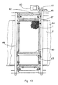
- Fig. 13 shows a planar container 67 containing a flat opened transport device 1 which is mounted in a frame 66.
- a medium 12 (not shown in the Figure) is distributed by an applicator device 63 that is driven by a motor 61 and drive shaft 62.
- Medium 12 is transferred contactless with a delivery device 80 over the whole width of a substrate 2 which is transported intermittently on a belt 64, e.g. from the device shown in Fig. 13 to a next one for applying a next colour.
- An encoder 65 provides the position of the applicator device 63 with reference to the transport device 1.
- Fig. 14 shows a modification of the device of Fig. 13 with a delivery device 81 which is not distributed over the whole width of the transport device 1, and instead is driven in the longitudinal direction of the applicator device 63 over the width of the transport device 1 by a second motor 68. This reduces the size of the delivery device 81. Via encoders 65 and 69 the position of the delivery device 81 is controlled.
- the device according to the invention, and the method according to the invention do not require the manufacture and patterning of stencils, as is currently necessary in the prior art.
- the speeds which can be achieved are in this case at least of the order of the speeds of currently customary methods.
- the method according to the invention can also be used for producing patterned stencils, which can be used in the conventional way, by using an unpatterned printing screen as a transport device for transporting liquid lacquer as a medium, and using a propelling device for selectively removing the medium from holes of the printing screen, and thereafter drying the lacquer.
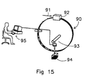
- Fig. 15 shows an application of the inventive ideas according to the invention in the field of metering of media.
- a transport device 90 provided with holes is rotated in the direction of arrow 91, and takes up medium in each of its holes from a container 92. The amount of medium in each hole is known.
- a propelling device 93 selectively removes the medium from predetermined holes of the transport device 90 to a container 94.
- the propelling device 93 is controlled by a computer 95, in which data relating to the amount of medium to be metered and/or the amount of medium per unit of time is stored and processed.
Landscapes
- Engineering & Computer Science (AREA)
- Mechanical Engineering (AREA)
- Screen Printers (AREA)
- Treatment Of Fiber Materials (AREA)
- Ink Jet (AREA)
- Printing Methods (AREA)
- Manufacturing Of Printed Wiring (AREA)
- Coating Apparatus (AREA)
- Application Of Or Painting With Fluid Materials (AREA)
Claims (53)
- Dispositif d'application d'une substance (12) à l'état de liquide, de pâte ou de poudre à un substrat (2) pour former un motif sur le substrat, le dispositif comprenant :dans lequel le dispositif de propulsion est prévu pour propulser la substance à partir de points sélectionnables de la zone de distribution, et des moyens de commande sont prévus pour commander le dispositif de propulsion afin de choisir les dits points ;un dispositif de transport (1) pour prendre la substance (12) et l'amener d'une manière répartie à une zone de distribution ; etun dispositif de distribution (3 à 6) pour transférer la substance (12) de la zone de distribution au substrat (2), le dispositif de distribution comportant un dispositif de propulsion avec une matière de propulsion qui est distincte de la substance, pour propulser la substance à partir de la zone de distribution,
caractérisé en ce que le dispositif de propulsion comporte des buses (6) agencées sur la largeur du dispositif de transport (1) et des vannes (5) respectivement connectées en amont de ces buses, et en ce que la matière de propulsion est un fluide. - Dispositif d'application d'une substance à l'état de liquide, de pâte ou de poudre à un substrat (58) pour former un motif sur le substrat, le dispositif comprenant :dans lequel le dispositif de propulsion est prévu pour propulser la substance à partir de points sélectionnables de la première zone de distribution, et des moyens de commande sont prévus pour commander le dispositif de propulsion afin de choisir les dits points ;un dispositif de transport (50), pour prendre la substance et l'amener ensuite d'une manière répartie à une première et une deuxième zones de distribution ;un dispositif de propulsion au moyen d'une matière de propulsion qui est distincte de la substance, pour propulser la substance à partir de la première zone de distribution ;un dispositif de distribution pour transférer la substance de la deuxième zone de distribution au substrat (58) ;
caractérisé en ce que le dispositif de propulsion comprend des buses (6) agencées sur la largeur du dispositif de transport (1) et des vannes (5) respectivement connectées en amont de ces buses, et en ce que la matière de propulsion est un fluide. - Dispositif selon la revendication 1 ou 2, caractérisé en ce que la substance est amenée de façon séparée à la zone de distribution ou à la première zone de distribution, respectivement.
- Dispositif selon une des revendications 1 à 3, caractérisé en ce que la commande du dispositif de propulsion est adapté à la vitesse de déplacement du dispositif de transport tout en tenant compte du motif à appliquer.
- Dispositif selon une des revendications 1 à 4, caractérisé en ce que la matière de propulsion est un fluide, en particulier de l'air.
- Dispositif selon la revendication 5, caractérisé en ce qu'on utilise un gaz dans une plage de pression comprise entre 103 et 106 Pa (0,01 et 10 bars).
- Dispositif selon une des revendications 1 à 6, caractérisé en ce que les vannes (5) peuvent être commandées à une fréquence de 0,1 kHz à 10 kHz et la matière de propulsion distribue la substance au substrat (2) sous l'action d'impulsions de gaz.
- Dispositif selon une des revendications 1 à 7, caractérisé en ce que les buses (6) sont agencées les unes à côté des autres en une pluralité de rangées, de préférence de 2 à 10 rangées, dans une direction de déplacement du dispositif de transport (1).
- Dispositif selon une des revendications 1 à 7, caractérisé en ce que les buses (6) sont agencées les unes à côté des autres et décalées les unes par rapport aux autres en une pluralité de rangées, de préférence de 2 à 16 rangées, dans une direction de déplacement du dispositif de transport (1).
- Dispositif selon une des revendications 1 à 7, caractérisé en ce que les buses sont agencées les unes à côté des autres en une pluralité de rangées, de préférence de 2 à 10 rangées, obliquement par rapport à une direction de déplacement du dispositif de transport (1).
- Dispositif selon une des revendications 1 à 10, caractérisé en ce que le dispositif de propulsion comporte un conduit d'amenée de gaz (15) qui s'étend sensiblement le long du dispositif de transport (1) et dont la variation de section transversale est prévue pour compenser la chute de pression hydrostatique et en particulier diminue à partir de l'orifice d'alimentation jusqu'à son extrémité.
- Dispositif selon la revendication 11, caractérisé en ce que le conduit d'amenée de gaz passe à l'intérieur du dispositif de transport.
- Dispositif selon une des revendications 1 à 12, caractérisé en ce que les buses peuvent s'incliner librement suivant un angle de ±90 degrés par rapport au dispositif de transport.
- Dispositif selon une des revendications 1 à 13, caractérisé en ce que les buses (6) peuvent être déplacées par rapport au dispositif de transport (1), en particulier perpendiculairement à sa direction de déplacement.
- Dispositif selon la revendication 14, caractérisé en ce que le déplacement des buses (6) est adapté à la distance entre les orifices (33) du dispositif de transport.
- Dispositif selon une des revendications 1 à 15, caractérisé en ce que le dispositif de transport (1) consiste en un tambour de transport rotatif pourvu de trous.
- Dispositif selon la revendication 16, caractérisé en ce qu'une position et une vitesse de rotation du tambour de transport sont réglables.
- Dispositif selon la revendication 17, caractérisé en ce que la position et la vitesse de rotation du tambour de transport sont adaptées à une position et une vitesse du substrat tout en tenant compte du motif à appliquer au substrat (2).
- Dispositif selon une des revendication 1 à 15, caractérisé en ce que le dispositif de transport (1) consiste en une courroie pourvue de trous et guidée autour d'au moins deux rouleaux.
- Dispositif selon la revendication 19, caractérisé en ce qu'une position et une vitesse de déplacement de la courroie sont réglables.
- Dispositif selon la revendication 20, caractérisé en ce que la position et la vitesse de déplacement de la courroie sont adaptées à une position et une vitesse du substrat tout en tenant compte du motif à appliquer au substrat (2).
- Dispositif selon une des revendications 16 à 21, caractérisé en ce que la position et la vitesse de rotation du tambour de transport ou la position et la vitesse de déplacement de la courroie, respectivement, et la position des trous sont mesurées par détection des trous.
- Dispositif selon une des revendications 16 à 21, caractérisé en ce que la position et la vitesse de rotation du tambour de transport ou la position et la vitesse de déplacement de la courroie, respectivement, et la position des trous sont détectées par un codeur.
- Dispositif selon la revendication 23, caractérisé en ce que le tambour ou la courroie de transport comprend au moins une série de trous de codage séparés prévus près d'un bord du tambour ou de la courroie de transport, respectivement, les trous de codage étant agencés de manière à être détectés par un codeur.
- Dispositif selon la revendication 22 ou 24, caractérisé en ce que les trous sont détectés sans contact.
- Dispositif selon la revendication 22, 24 ou 25, caractérisé en ce que les trous sont détectés par un dispositif de détection de champ électromagnétique.
- Dispositif selon une des revendications 1 à 26, caractérisé en ce que le dispositif de transport (1) et le substrat (2) se déplacent en sens inverse l'un de l'autre.
- Dispositif selon une des revendications 20 à 27, caractérisé en ce que le dispositif de transport (1) est placé à une distance du substrat (2) comprise entre 0,1 et 100 mm, en particulier à une distance du substrat (2) comprise entre 1 et 10 mm.
- Dispositif selon une des revendications 1 à 28, caractérisé en ce que la distance entre le dispositif de propulsion et le dispositif de transport (1) est comprise entre 0,01 et 10 mm, en particulier entre 0,1 et 2,0 mm.
- Dispositif selon une des revendications 20 à 29, caractérisé en ce qu'un récipient (8) pour la substance est prévu à l'intérieur ou à l'extérieur du dispositif de transport ou sur ses deux côtés.
- Dispositif selon la revendication 30, caractérisé en ce qu'il comprend un rouleau de distribution (9) pour transférer la substance du récipient (8) au dispositif de transport (1), et un rouleau d'accompagnement magnétique ou mécanique (10) est placé en face du rouleau de distribution (9), du côté arrière du dispositif de transport (1) par rapport au rouleau de distribution (9).
- Dispositif selon la revendication 30 ou 31, caractérisé en ce qu'il comprend au moins un dispositif applicateur (7) pour le dosage de la substance (12) extraite du récipient (8).
- Dispositif selon la revendication 32, caractérisé en ce que le dispositif applicateur comprend un moyen de raclage à lame et/ou un moyen de raclage à rouleau.
- Dispositif selon la revendication 30 ou 32, caractérisé en ce que la substance (12) est amenée d'un récipient (8') à un tube de distribution (13) qui est agencé dans le dispositif de transport (1) et s'étend le long du dispositif de transport, et qui comporte des perforations.
- Dispositif selon une des revendications 30 à 34, caractérisé en ce qu'il comprend une plaque d'évacuation (14) qui est prévue au-dessous du dispositif de transport (1) pour ramener la substance en excès (12) au récipient (8).
- Dispositif selon une des revendications 1 à 35, caractérisé en ce que le substrat (2) est amené sur une courroie sans fin (21) montée sur deux rouleaux de renvoi ou plus.
- Dispositif selon la revendication 36, caractérisé en ce que le substrat (2) est lié par collage à la courroie sans fin (21).
- Système d'application d'une substance (12) à l'état de liquide, de poudre ou de pâte à un substrat (2) amené dans une direction prédéterminée, comprenant une pluralité de dispositifs (25) selon une des revendications 1 à 37, qui sont agencés les uns derrière les autres dans ladite direction, les dispositifs pouvant être commandés par une unité centrale de traitement commune, ou bien chaque dispositif étant commandé séparément de façon décentralisée.
- Procédé d'utilisation du système selon la revendication 38, dans lequel tous les dispositifs (25) pendant leur fonctionnement sont commandés en synchronisme les uns avec les autres par l'unité centrale de traitement, ou de façon décentralisée par des dispositifs de commande individuels respectifs mutuellement en communication, pour former sur le substrat un motif composé de motifs formés par les différents dispositifs tous en synchronisme.
- Procédé d'application d'une substance (12) à l'état de liquide, de poudre ou de pâte à un substrat (2) pour former un motif sur le substrat, dans lequel la substance (12) est prise par un dispositif de transport (1) et amenée d'une manière répartie à une zone de distribution dans laquelle un dispositif de propulsion propulse la substance à partir de la zone de distribution, au moyen d'une matière de propulsion qui est distincte de la substance, pour transférer la substance (12) au substrat (2), et dans lequel la substance est propulsée à partir de points choisis de la zone de distribution sous la commande de moyens de commande, caractérisé en ce que la matière de propulsion est un fluide.
- Procédé d'application d'une substance à l'état de liquide, de poudre ou de pâte, à un substrat (58) pour former un dessin sur le substrat, dans lequel la substance est prise par un dispositif de transport (50) et amenée ensuite d'une manière répartie à une première et une deuxième zones de distribution et, dans ladite première zone de distribution, un dispositif de propulsion propulse la substance avec une matière de propulsion qui est distincte de la substance, et dans lequel la substance est propulsée à partir de points sélectionnés de la première zone de distribution sous la commande de moyens de commande, et la substance est ensuite transférée de la deuxième zone de distribution au substrat (58), caractérisé en ce que la matière de propulsion est un fluide.
- Procédé selon la revendication 40 ou 41, caractérisé en ce que des impulsions de gaz à une fréquence de 0,1 kHz à 10 kHz sont utilisées comme moyen de propulsion.
- Procédé selon une des revendications 40 à 42, caractérisé en ce que la substance (12) est amenée au substrat (2) sans contact entre le dispositif de transport (1) et le dispositif de propulsion.
- Procédé selon une des revendications 40 à 43, caractérisé en ce que des adjuvants d'impression sont appliqués au substrat (2) avant l'application de la substance au substrat (2).
- Procédé selon la revendication 44, caractérisé en ce que les adjuvants d'impression sont appliqués au substrat (2) lorsqu'il est sec.
- Procédé selon la revendication 44, caractérisé en ce que les adjuvants d'impression sont appliqués au substrat (2) lorsqu'il est humide.
- Procédé selon la revendication 46, caractérisé en ce qu'un traitement de séchage est effectué après application des adjuvants d'impression, afin de sécher le substrat (2) à une teneur en humidité résiduelle de 2 à 15%.
- Procédé selon une des revendications 40 à 47, caractérisé en ce que les couleurs sont mélangées sur le substrat (2) après une séparation de couleur appropriée.
- Utilisation du dispositif selon une des revendications 1 à 37, du système selon la revendication 38 ou du procédé selon une des revendications 39 à 48, pour appliquer un motif à des substrats de grande surface, en particulier des produits textiles, par application d'une encre d'impression à des régions particulières d'un support d'impression.
- Utilisation du dispositif selon une des revendications 1 à 37, du système selon la revendication 38 ou du procédé selon une des revendications 39 à 48, pour appliquer une substance à des supports d'impression de motif, en particulier à un écran de sérigraphie, fabriqués en métal ou en matière plastique.
- Utilisation du dispositif selon une des revendications 1 à 37, du dispositif selon la revendication 38 ou du procédé selon une des revendications 39 à 48, pour la configuration d'une forme d'impression constituant le substrat, par application d'une substance de configuration à la forme d'impression.
- Utilisation selon la revendication 51, dans laquelle la substance de configuration est un vernis de configuration, un masque de configuration, une cire ou une encre.
- Tambour ou courroie de transport pour un dispositif selon une des revendications 22 à 26, pour l'application d'une substance à l'état de liquide, de pâte ou de poudre à un substrat afin de former un motif sur le substrat, le tambour ou la courroie de transport comportant des trous de passage de substance pour prendre et distribuer la substance de façon discrète et pour propulser la substance à partir des trous de passage de substance sélectivement au moyen d'un fluide provenant de buses agencées sur la largeur du tambour ou de la courroie de transport, des vannes (5) étant respectivement montées en amont de ces buses, le tambour ou la courroie de transport comportant en outre une série de trous de codage séparés prévus près d'un bord du tambour ou de la courroie de transport, respectivement, les trous de codage étant placés en relation fixe par rapport aux trous de passage de substance et étant agencés de manière à être détectés par un codeur afin de synchroniser la commande des vannes avec la position des trous de passage de substance du tambour ou de la courroie de transport.
Applications Claiming Priority (3)
| Application Number | Priority Date | Filing Date | Title |
|---|---|---|---|
| DE19806040 | 1998-02-13 | ||
| DE19806040A DE19806040A1 (de) | 1998-02-13 | 1998-02-13 | Vorrichtung und Verfahren zum Aufbringen eines Mediums auf ein Substrat und System mit mehreren solchen Vorrichtungen |
| PCT/NL1999/000074 WO1999041081A1 (fr) | 1998-02-13 | 1999-02-12 | Dispositif et procede d'application d'une substance sur un substrat, systeme comprenant plusieurs de ces dispositifs et utilisation de ces dispositif, procede et systeme |
Publications (2)
| Publication Number | Publication Date |
|---|---|
| EP1076608A1 EP1076608A1 (fr) | 2001-02-21 |
| EP1076608B1 true EP1076608B1 (fr) | 2003-06-25 |
Family
ID=7857697
Family Applications (1)
| Application Number | Title | Priority Date | Filing Date |
|---|---|---|---|
| EP99932485A Expired - Lifetime EP1076608B1 (fr) | 1998-02-13 | 1999-02-12 | Dispositif et procede d'application d'une substance sur un substrat, systeme comprenant plusieurs de ces dispositifs et utilisation de ces dispositif, procede et systeme |
Country Status (10)
| Country | Link |
|---|---|
| US (1) | US6458211B1 (fr) |
| EP (1) | EP1076608B1 (fr) |
| JP (1) | JP2002502740A (fr) |
| CN (1) | CN1291136A (fr) |
| AT (1) | ATE243621T1 (fr) |
| AU (1) | AU3278099A (fr) |
| BR (1) | BR9907851A (fr) |
| DE (2) | DE19806040A1 (fr) |
| ES (1) | ES2203157T3 (fr) |
| WO (1) | WO1999041081A1 (fr) |
Families Citing this family (20)
| Publication number | Priority date | Publication date | Assignee | Title |
|---|---|---|---|---|
| NL1011993C2 (nl) * | 1999-05-07 | 2000-11-09 | Stork Brabant Bv | Zeefdrukinrichting met een in een sjabloon verplaatsbare reinigingseenheid. |
| IT1316968B1 (it) | 2000-12-15 | 2003-05-13 | Iri S R L | Decoratrice superficiale in continuo di prodotti, particolarmentepiastrelle ceramiche. |
| US7037501B2 (en) | 2001-01-04 | 2006-05-02 | Regents Of The University Of Minnesota | Myostatin immnoconjugate |
| US20040123751A1 (en) * | 2001-07-12 | 2004-07-01 | Ramon Vega | Multi-purpose printer device |
| ITFI20020029A1 (it) * | 2002-02-18 | 2003-08-18 | Gruppo Concorde Spa | Metodo e dispositivo per la decorazione per serigrafia di piastrelle ceramiche o simili |
| ITMO20050126A1 (it) * | 2005-05-23 | 2006-11-24 | Paola Ferrari | Retino a rullo per decoro di piastrelle con ugelli a getto fluidodinamico. |
| ITMI20080651A1 (it) * | 2008-04-11 | 2009-10-12 | O Pac S R L | Macchina per la trasformazione in linea di prodotti monouso, stampati a caldo con cere e paraffine colorate |
| EP2582470B1 (fr) | 2010-06-15 | 2020-09-09 | 3M Innovative Properties Company | Collecteur de distribution à aiguilles de distribution multiples |
| US8668998B2 (en) | 2011-01-31 | 2014-03-11 | Samsung Sdi Co., Ltd. | Secondary battery |
| CN102248753A (zh) * | 2011-04-27 | 2011-11-23 | 苏州工业园区天势科技有限公司 | 多色孔版印刷机 |
| US10144016B2 (en) * | 2015-10-30 | 2018-12-04 | The Procter & Gamble Company | Apparatus for non-contact printing of actives onto web materials and articles |
| EP3426212B1 (fr) | 2016-03-11 | 2020-10-21 | The Procter and Gamble Company | Bandes non tissées texturées avec des compositions |
| CN106939149B (zh) * | 2017-03-07 | 2018-09-14 | 黑龙江林海华安新材料股份有限公司 | 一种聚氨酯热熔胶加湿剂及使用该加湿剂的贴膜方法 |
| US11813148B2 (en) | 2018-08-03 | 2023-11-14 | The Procter And Gamble Company | Webs with compositions applied thereto |
| US11730639B2 (en) | 2018-08-03 | 2023-08-22 | The Procter & Gamble Company | Webs with compositions thereon |
| DE102019105920B4 (de) * | 2019-03-08 | 2022-06-09 | Canon Production Printing Holding B.V. | Verfahren und Auftragswerk zum Auftragen einer Flüssigkeit auf ein Substrat |
| KR102225915B1 (ko) | 2019-07-05 | 2021-03-10 | 윈엔윈(주) | 배드민턴 라켓 |
| US12000085B2 (en) | 2020-07-01 | 2024-06-04 | Daniel Greene | Method for live area printing for dark colored textiles |
| CN115646733B (zh) * | 2022-10-31 | 2025-12-05 | 绍兴锦居装饰材料有限公司 | 一种抗菌防霉墙布的生产工艺及墙布表面涂布系统 |
| CN116001427A (zh) * | 2022-12-22 | 2023-04-25 | 通威太阳能(成都)有限公司 | 一种丝网印刷方法与设备 |
Citations (1)
| Publication number | Priority date | Publication date | Assignee | Title |
|---|---|---|---|---|
| EP0836939A1 (fr) * | 1995-06-20 | 1998-04-22 | MAXIMOVSKY, Sergei Nicolaevich | Appareil d'impression |
Family Cites Families (13)
| Publication number | Priority date | Publication date | Assignee | Title |
|---|---|---|---|---|
| AT175956B (de) * | 1951-03-16 | 1953-09-10 | Ernst Ing Wagner | Verfahren und Vorrichtung zum Aufbringen flüssiger Stoffe auf eine Unterlage |
| ZA776523B (en) * | 1977-04-16 | 1978-08-30 | Heidelberger Druckmasch Ag | Dampening unit for offset printing presses |
| US4324117A (en) * | 1980-06-11 | 1982-04-13 | The Mead Corporation | Jet device for application of liquid dye to a fabric web |
| DE3101766C1 (de) * | 1981-01-21 | 1982-09-09 | Saueressig Gmbh, 4422 Ahaus | Rotationssiebdruckvorrichtung |
| DE3146828C2 (de) * | 1981-09-23 | 1983-12-01 | Kleinewefers Gmbh, 4150 Krefeld | Vorrichtung zum kontinuierlichen Auftragen einer Kleinstmenge an Flüssigkeit auf eine Materialbahn |
| DE3137794C2 (de) * | 1981-09-23 | 1983-09-29 | Kleinewefers Gmbh, 4150 Krefeld | Vorrichtung zum kontinuierlichen Auftragen einer Kleinstmenge an Flüssigkeit auf eine Materialbahn |
| JPS61238465A (ja) * | 1985-04-16 | 1986-10-23 | Nec Corp | クリ−ムはんだ塗布装置 |
| JPS63194865A (ja) * | 1987-02-06 | 1988-08-12 | Toshiba Corp | スプレ−フラツクサ− |
| DE4001452C2 (de) * | 1990-01-19 | 1998-09-10 | Wako Walzen Konstruktion Syste | Vorrichtung zum kontinuierlichen Auftragen einer Flüssigkeit auf eine Materialbahn |
| DE9111789U1 (de) * | 1991-09-20 | 1991-11-14 | Wako Walzen Konstruktion Systembau GmbH, 4150 Krefeld | Vorrichtung zum kontinuierlichen Auftragen einer Flüssigkeit auf eine Materialbahn |
| US5584932A (en) * | 1995-04-12 | 1996-12-17 | Nordson Corporation | Electrical control circuit for controlling the speed and position of a rotary screen coater with respect to the line speed and position of a moving web |
| US5877788A (en) * | 1995-05-09 | 1999-03-02 | Moore Business Forms, Inc. | Cleaning fluid apparatus and method for continuous printing ink-jet nozzle |
| JP3618403B2 (ja) * | 1995-06-19 | 2005-02-09 | 理想科学工業株式会社 | 孔版印刷装置 |
-
1998
- 1998-02-13 DE DE19806040A patent/DE19806040A1/de not_active Ceased
-
1999
- 1999-02-12 DE DE69909080T patent/DE69909080T2/de not_active Expired - Fee Related
- 1999-02-12 AU AU32780/99A patent/AU3278099A/en not_active Abandoned
- 1999-02-12 AT AT99932485T patent/ATE243621T1/de not_active IP Right Cessation
- 1999-02-12 ES ES99932485T patent/ES2203157T3/es not_active Expired - Lifetime
- 1999-02-12 CN CN99802960A patent/CN1291136A/zh active Pending
- 1999-02-12 JP JP2000531309A patent/JP2002502740A/ja not_active Withdrawn
- 1999-02-12 EP EP99932485A patent/EP1076608B1/fr not_active Expired - Lifetime
- 1999-02-12 BR BR9907851-1A patent/BR9907851A/pt unknown
- 1999-02-12 WO PCT/NL1999/000074 patent/WO1999041081A1/fr not_active Ceased
-
2000
- 2000-08-14 US US09/637,580 patent/US6458211B1/en not_active Expired - Fee Related
Patent Citations (1)
| Publication number | Priority date | Publication date | Assignee | Title |
|---|---|---|---|---|
| EP0836939A1 (fr) * | 1995-06-20 | 1998-04-22 | MAXIMOVSKY, Sergei Nicolaevich | Appareil d'impression |
Also Published As
| Publication number | Publication date |
|---|---|
| DE69909080T2 (de) | 2004-05-06 |
| CN1291136A (zh) | 2001-04-11 |
| EP1076608A1 (fr) | 2001-02-21 |
| JP2002502740A (ja) | 2002-01-29 |
| DE69909080D1 (de) | 2003-07-31 |
| AU3278099A (en) | 1999-08-30 |
| ES2203157T3 (es) | 2004-04-01 |
| US6458211B1 (en) | 2002-10-01 |
| BR9907851A (pt) | 2000-10-24 |
| WO1999041081A1 (fr) | 1999-08-19 |
| ATE243621T1 (de) | 2003-07-15 |
| DE19806040A1 (de) | 1999-09-09 |
Similar Documents
| Publication | Publication Date | Title |
|---|---|---|
| EP1076608B1 (fr) | Dispositif et procede d'application d'une substance sur un substrat, systeme comprenant plusieurs de ces dispositifs et utilisation de ces dispositif, procede et systeme | |
| US11485131B2 (en) | Machine arrangement with printing unit for the sequential processing of sheet-type substrates | |
| CN107548358B (zh) | 具有多个用于单张纸的加工站的机器结构和用于运行机器结构的方法 | |
| US3915087A (en) | Multi-color multiple offset single impression screen printer | |
| US5099758A (en) | Apparatus for applying a flowable medium to a surface, especially a web, roll or the like | |
| EP3953519B1 (fr) | Procédé et appareil pour impression textile numérique | |
| NL8500169A (nl) | Gecombineerde rotatiedrukpers. | |
| CN112339425A (zh) | 用于依次加工单张纸状基材的方法和机器结构 | |
| CN110582409A (zh) | 聚氨酯树脂在纺织品上的旋转筛网图案印花 | |
| US4742699A (en) | Apparatus for coloring textile materials | |
| CN101346232B (zh) | 将应用层转移至印张上的方法或设备 | |
| US4998470A (en) | Screen printing machine having an inclined screen | |
| CN102625748A (zh) | 转轮丝网印刷装置和转轮丝网印刷方法 | |
| EP0306568A1 (fr) | Installation et procédé pour l'application d'un liquide de traitement sur une matière en bande | |
| US8408674B1 (en) | System and method for incorporating inkjet printing into a printing press process | |
| MXPA00007916A (en) | Device and method for applying a medium to a substrate, system having a plurality of such devices, and use of such device, method and system | |
| US5674571A (en) | Method and apparatus for the coating of liquids onto film webs, particularly of color prints | |
| JP4740255B2 (ja) | グラビアシリンダパッチコーティング装置および方法 | |
| CN114786953B (zh) | 印刷片材的设备和方法 | |
| IL99896A (en) | Printing method and apparatu | |
| US20160052258A1 (en) | Method and device for printing on a substrate | |
| Goossens | Rotary screen coating | |
| CN110267814A (zh) | 用于操作用于印刷空心体的装置的方法 | |
| WO2001069324A1 (fr) | Procede et dispositif pour produire des bandes textiles, notamment des etiquettes, imprimees numeriquement | |
| HK40127923A (en) | Method and apparatus for digital textile printing |
Legal Events
| Date | Code | Title | Description |
|---|---|---|---|
| PUAI | Public reference made under article 153(3) epc to a published international application that has entered the european phase |
Free format text: ORIGINAL CODE: 0009012 |
|
| 17P | Request for examination filed |
Effective date: 20000811 |
|
| AK | Designated contracting states |
Kind code of ref document: A1 Designated state(s): AT CH DE ES FR GB IT LI NL |
|
| 17Q | First examination report despatched |
Effective date: 20010606 |
|
| GRAH | Despatch of communication of intention to grant a patent |
Free format text: ORIGINAL CODE: EPIDOS IGRA |
|
| GRAH | Despatch of communication of intention to grant a patent |
Free format text: ORIGINAL CODE: EPIDOS IGRA |
|
| RAP1 | Party data changed (applicant data changed or rights of an application transferred) |
Owner name: STORK PRINTS B.V. |
|
| GRAA | (expected) grant |
Free format text: ORIGINAL CODE: 0009210 |
|
| AK | Designated contracting states |
Designated state(s): AT CH DE ES FR GB IT LI NL |
|
| REG | Reference to a national code |
Ref country code: GB Ref legal event code: FG4D |
|
| REG | Reference to a national code |
Ref country code: CH Ref legal event code: EP |
|
| REF | Corresponds to: |
Ref document number: 69909080 Country of ref document: DE Date of ref document: 20030731 Kind code of ref document: P |
|
| REG | Reference to a national code |
Ref country code: CH Ref legal event code: NV Representative=s name: PATENTANWAELTE BREITER + WIEDMER AG |
|
| REG | Reference to a national code |
Ref country code: ES Ref legal event code: FG2A Ref document number: 2203157 Country of ref document: ES Kind code of ref document: T3 |
|
| PLBE | No opposition filed within time limit |
Free format text: ORIGINAL CODE: 0009261 |
|
| STAA | Information on the status of an ep patent application or granted ep patent |
Free format text: STATUS: NO OPPOSITION FILED WITHIN TIME LIMIT |
|
| ET | Fr: translation filed | ||
| 26N | No opposition filed |
Effective date: 20040326 |
|
| PGFP | Annual fee paid to national office [announced via postgrant information from national office to epo] |
Ref country code: GB Payment date: 20070129 Year of fee payment: 9 |
|
| PGFP | Annual fee paid to national office [announced via postgrant information from national office to epo] |
Ref country code: ES Payment date: 20070222 Year of fee payment: 9 Ref country code: DE Payment date: 20070222 Year of fee payment: 9 |
|
| PGFP | Annual fee paid to national office [announced via postgrant information from national office to epo] |
Ref country code: AT Payment date: 20070223 Year of fee payment: 9 |
|
| PGFP | Annual fee paid to national office [announced via postgrant information from national office to epo] |
Ref country code: CH Payment date: 20070227 Year of fee payment: 9 |
|
| PGFP | Annual fee paid to national office [announced via postgrant information from national office to epo] |
Ref country code: NL Payment date: 20070228 Year of fee payment: 9 |
|
| REG | Reference to a national code |
Ref country code: CH Ref legal event code: PFA Owner name: STORK PRINTS B.V. Free format text: STORK PRINTS B.V.#RAAMSTRAAT 3#5831 AT BOXMEER (NL) -TRANSFER TO- STORK PRINTS B.V.#RAAMSTRAAT 3#5831 AT BOXMEER (NL) |
|
| PGFP | Annual fee paid to national office [announced via postgrant information from national office to epo] |
Ref country code: IT Payment date: 20070427 Year of fee payment: 9 |
|
| PGFP | Annual fee paid to national office [announced via postgrant information from national office to epo] |
Ref country code: FR Payment date: 20070227 Year of fee payment: 9 |
|
| REG | Reference to a national code |
Ref country code: CH Ref legal event code: PL |
|
| GBPC | Gb: european patent ceased through non-payment of renewal fee |
Effective date: 20080212 |
|
| PG25 | Lapsed in a contracting state [announced via postgrant information from national office to epo] |
Ref country code: LI Free format text: LAPSE BECAUSE OF NON-PAYMENT OF DUE FEES Effective date: 20080229 Ref country code: CH Free format text: LAPSE BECAUSE OF NON-PAYMENT OF DUE FEES Effective date: 20080229 |
|
| NLV4 | Nl: lapsed or anulled due to non-payment of the annual fee |
Effective date: 20080901 |
|
| PG25 | Lapsed in a contracting state [announced via postgrant information from national office to epo] |
Ref country code: NL Free format text: LAPSE BECAUSE OF NON-PAYMENT OF DUE FEES Effective date: 20080901 Ref country code: AT Free format text: LAPSE BECAUSE OF NON-PAYMENT OF DUE FEES Effective date: 20080212 |
|
| REG | Reference to a national code |
Ref country code: FR Ref legal event code: ST Effective date: 20081031 |
|
| PG25 | Lapsed in a contracting state [announced via postgrant information from national office to epo] |
Ref country code: DE Free format text: LAPSE BECAUSE OF NON-PAYMENT OF DUE FEES Effective date: 20080902 |
|
| PG25 | Lapsed in a contracting state [announced via postgrant information from national office to epo] |
Ref country code: FR Free format text: LAPSE BECAUSE OF NON-PAYMENT OF DUE FEES Effective date: 20080229 |
|
| REG | Reference to a national code |
Ref country code: ES Ref legal event code: FD2A Effective date: 20080213 |
|
| PG25 | Lapsed in a contracting state [announced via postgrant information from national office to epo] |
Ref country code: GB Free format text: LAPSE BECAUSE OF NON-PAYMENT OF DUE FEES Effective date: 20080212 |
|
| PG25 | Lapsed in a contracting state [announced via postgrant information from national office to epo] |
Ref country code: ES Free format text: LAPSE BECAUSE OF NON-PAYMENT OF DUE FEES Effective date: 20080213 |
|
| PG25 | Lapsed in a contracting state [announced via postgrant information from national office to epo] |
Ref country code: IT Free format text: LAPSE BECAUSE OF NON-PAYMENT OF DUE FEES Effective date: 20080212 |