EP1076786B1 - Hydraulischer steuerkreis für ein stufenlos regelbares getriebe - Google Patents
Hydraulischer steuerkreis für ein stufenlos regelbares getriebe Download PDFInfo
- Publication number
- EP1076786B1 EP1076786B1 EP99922272A EP99922272A EP1076786B1 EP 1076786 B1 EP1076786 B1 EP 1076786B1 EP 99922272 A EP99922272 A EP 99922272A EP 99922272 A EP99922272 A EP 99922272A EP 1076786 B1 EP1076786 B1 EP 1076786B1
- Authority
- EP
- European Patent Office
- Prior art keywords
- valve
- fluid
- control circuit
- point
- clutch
- Prior art date
- Legal status (The legal status is an assumption and is not a legal conclusion. Google has not performed a legal analysis and makes no representation as to the accuracy of the status listed.)
- Expired - Lifetime
Links
- 239000012530 fluid Substances 0.000 claims description 93
- 238000011144 upstream manufacturing Methods 0.000 claims description 21
- 230000005540 biological transmission Effects 0.000 claims description 17
- 230000008859 change Effects 0.000 claims description 13
- 230000007246 mechanism Effects 0.000 claims description 10
- 230000000694 effects Effects 0.000 claims description 5
- 238000001514 detection method Methods 0.000 claims description 3
- 238000005086 pumping Methods 0.000 claims description 2
- 238000006243 chemical reaction Methods 0.000 description 5
- 238000000034 method Methods 0.000 description 5
- 230000008569 process Effects 0.000 description 5
- 238000013016 damping Methods 0.000 description 4
- 230000033001 locomotion Effects 0.000 description 4
- 238000005429 filling process Methods 0.000 description 2
- 230000002411 adverse Effects 0.000 description 1
- 230000003190 augmentative effect Effects 0.000 description 1
- 238000002485 combustion reaction Methods 0.000 description 1
- 230000006866 deterioration Effects 0.000 description 1
- 230000000977 initiatory effect Effects 0.000 description 1
- 230000004048 modification Effects 0.000 description 1
- 238000012986 modification Methods 0.000 description 1
- 230000004044 response Effects 0.000 description 1
- 230000000630 rising effect Effects 0.000 description 1
- 239000013589 supplement Substances 0.000 description 1
- 230000001360 synchronised effect Effects 0.000 description 1
Images


Classifications
-
- F—MECHANICAL ENGINEERING; LIGHTING; HEATING; WEAPONS; BLASTING
- F16—ENGINEERING ELEMENTS AND UNITS; GENERAL MEASURES FOR PRODUCING AND MAINTAINING EFFECTIVE FUNCTIONING OF MACHINES OR INSTALLATIONS; THERMAL INSULATION IN GENERAL
- F16H—GEARING
- F16H61/00—Control functions within control units of change-speed- or reversing-gearings for conveying rotary motion ; Control of exclusively fluid gearing, friction gearing, gearings with endless flexible members or other particular types of gearing
- F16H61/66—Control functions within control units of change-speed- or reversing-gearings for conveying rotary motion ; Control of exclusively fluid gearing, friction gearing, gearings with endless flexible members or other particular types of gearing specially adapted for continuously variable gearings
- F16H61/664—Friction gearings
- F16H61/6648—Friction gearings controlling of shifting being influenced by a signal derived from the engine and the main coupling
-
- F—MECHANICAL ENGINEERING; LIGHTING; HEATING; WEAPONS; BLASTING
- F16—ENGINEERING ELEMENTS AND UNITS; GENERAL MEASURES FOR PRODUCING AND MAINTAINING EFFECTIVE FUNCTIONING OF MACHINES OR INSTALLATIONS; THERMAL INSULATION IN GENERAL
- F16H—GEARING
- F16H61/00—Control functions within control units of change-speed- or reversing-gearings for conveying rotary motion ; Control of exclusively fluid gearing, friction gearing, gearings with endless flexible members or other particular types of gearing
- F16H61/66—Control functions within control units of change-speed- or reversing-gearings for conveying rotary motion ; Control of exclusively fluid gearing, friction gearing, gearings with endless flexible members or other particular types of gearing specially adapted for continuously variable gearings
- F16H61/664—Friction gearings
Definitions
- the present invention relates to an hydraulic control circuit for a continuously variable transmission and relates particularly, but not exclusively, to such a circuit for what is commonly referred to as a "full toroidal" continuously variable transmission. (CVT).
- CVT continuously variable transmission.
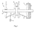
- Such CVT's comprise an input shaft for receiving power from, for example, an internal combustion engine and has mounted thereon a pair of spaced apart input discs and a pair of output discs mounted back to back between said input discs.
- the input discs rotate with the shaft but the output discs are mounted for free rotation on the shaft by means of a bearing or some such similar device.
- the confronting faces of the input and output discs are contoured to provide a concave surface or face, which mirrors that of the face facing it.
- the faces are either formed in a full or half toroidal manner and provide the surfaces between which a plurality of rollers are positioned for transmitting power between the input and the output discs.
- the discs are hydraulically end loaded to ensure that traction is maintained between the discs and the roller. Additionally, the rollers themselves, whilst having a certain degree of freedom of movement are subjected to some degree of positional influence by an hydraulic actuator employing both the higher and the lower pressures within an hydraulic control circuit, such as disclosed in PCT GB/00956 or British Patent No. 2282196
- valves 99 and 100 are connected in parallel and are operable either individually or together to vary the pressure within the hydraulic control circuit in order to influence the position of the rollers 22 and the hydraulic pressure being applied to either of two clutches 37, 43.
- the control is independent i.e. varying the hydraulic pressure in the clutches has no affect on the position of the rollers and vice versa.
- GB-A-2312258 discloses the features according to the preamble of present claim 1.
- the present invention provides an hydraulic control circuit for a CVT transmission having a variator and a plurality of regime change clutches comprising:
- the first fluid directing valve means comprises two two-way valves S 1 , S 2 and each having first and second outlets, each first outlet being connected for supplying fluid to said first point (upstream of V 1 ) and each second outlet being connected for supplying fluid to said second point (between V 1 and V 2 ).
- valve V 1 comprises a pressure raising valve for controlling pressure upstream thereof for supply to said variator and in which any flow through said valve V 1 is combined with any flow being directed directly to said second point for subsequent supply to said second (clutch control valve) V 2 .
- the circuit further includes flow restriction means (R) for restricting the flow of fluid in the direct supply between the fluid directing valve means (S 1 , S 2 ) and said second point such that the resistance in each branch is substantially equal to the total resistance in the supply route through valve V 1 .
- R flow restriction means
- the circuit includes a further restrictor r within the supply to valve V 1 and the total resistance of r and the resistance in Valve V 1 is substantially equal to the resistance R and any resistance within each branch between the fluid directing valve means (S 1 , S 2 ) and the second point (P 2 ).
- the circuit further includes a vehicle deceleration monitor and switching means operable to switch the first fluid directing valve to cause all the fluid from pumps P L , P R to be directed to valve V 1 upon detection of vehicle breaking/deceleration.
- the circuit includes switching means operable to switch the first fluid-directing valve to cause all the fluid from pumps P L , P R to be directed to said second point rather than said first point.
- the circuit includes first and second regime change clutches C R , C L respectively and in which each clutch C R , C L is connected for receiving fluid from a point downstream of pumps P R , P L respectively.
- the circuit includes a flow restrictor r L , r R in the supply to each clutch, thereby to maintain a predetermined pressure within the supply leading thereto.
- each clutch supply includes a clutch fill valve F L , F R between an associated pump and said clutch, said valve receiving fluid flow from said associated pump either via a primary fill point P FP downstream of said second point but upstream of valve V 2 or from a secondary fill point S FP downstream of said pumps but upstream of said first point P 1 .
- the secondary fill point S FP is upstream of said first fluid directing valve means (S 1 , S 2 ).
- the circuit Whenever the circuit is provided with clutches it preferably includes a dump value (E L E R ) for each clutch acting in a first position to direct flow to said associated clutch and in a second position acting to allow fluid to drain therefrom but preventing fluid flowing thereto.
- E L E R a dump value for each clutch acting in a first position to direct flow to said associated clutch and in a second position acting to allow fluid to drain therefrom but preventing fluid flowing thereto.
- the circuit includes control means for controlling valves P L , F R so as to cause fluid to be supplied from the primary fill point P FP during a clutch fill step and from the secondary fill point S FP during a clutch engage step.
- the circuit may include control means for controlling the first fluid directing valve S 1 , S 2 to direct fluid from both pumps P 1 , P 2 to a particular clutch C L C R via said secondary fill point S FP
- the circuit further includes a fluid accumulator for receiving fluid flow once clutch engagement has been completed.
- said accumulator receives fluid from a tertiary filling point T FP upstream of valve V 2 but downstream of the primary filling point P FP .
- valve V 2 comprises a solenoid valve.
- the circuit further includes a variable rate relief valve and valve V 2 comprises a solenoid valve, said valve V 2 in a first position acting to direct flow through said valve and to a sump and in a second position acting to direct fluid to said variable rate relief value.
- said variable rate relief valve comprises a spring loaded pressure relief valve having a "timing restrictor" circuit for receiving a portion of the flow and directing it to the spring side of the accumulator, thereby to assist the spring effect and increase the pressure within the hydraulic circuit.
- said pressure relief valve includes a drain for draining any fluid accumulated on the spring side of said valve.
- the circuit includes an hydraulically actuated end load mechanism of a continuously-variable-transmission and said circuit includes means (highest wins valve) for supplying said end load mechanism with the higher of the two pressures created by pumps P L , P R .
- the above arrangement includes a pressure sensitive valve (H w ) connected for receiving hydraulic fluid from both pumps P L , P R and for directing only the fluid at the higher pressure to the end loading mechanism.
- H w pressure sensitive valve
- the circuit may be provided with means for supplying said end load mechanism with fluid at the lowest pressure within the circuit as an alternative to fluid at the higher of the two pressures created by pumps P L , P R .
- the hydraulic control circuit further includes switching means for switching the supply fluid being supplied to the end load mechanism between that at the lower pressure and that at the higher pressure.
- the present invention comprises a continuously variable transmission having an hydraulic control circuit as described above.
- the present arrangement comprises a modification of that described above but adopts a similar strategy of control as will be described later herein.
- the present invention comprises a control circuit 30 having first and second fluid pumps P L P R , each of which supplies fluid from a reservoir or sump 32 and directs it to first and second supply pipes 34, 36 respectively.
- a valving arrangement V 3 which may comprise a single or two individual solenoid valves S 1 S 2 respectively.
- valve or valves is/are arranged such that the supply from each of pumps P L , P R may be selectively directed to either a first point P 1 upstream of a control valve V 1 or to a second point P 2 downstream of said valve but upstream of a further valve V 2 .
- Valves V 1 and V 2 are pressure raising valves, i.e. operation thereof restricts the flow therethrough and raises the pressure in the supply thereto whilst valve V 3 and / or S 1 , S 2 are simple solenoid valves having no effect on the line pressure. It is important to note that control valves V 1 and V 2 are connected in flow series as opposed to being arranged in parallel as disclosed in PCT GB/00956, mentioned above.
- the solenoid valves are clearly arranged to connect either or both of supply pipe 34, 36 to valve V 1 or V 2 and, in the connection arrangement shown in this figure P 2 > P 1 by the ⁇ P across V 1 .
- the ⁇ P across V 2 sets the absolute pressures within the control circuit without affecting the ⁇ P across the pumps and has no effect on V 1 (unless flows from the pumps change, e.g. as a result of pressure relief valves). Consequently, V 1 may be employed as the variator control valve whilst V 2 may be employed as the clutch control valve. In such an arrangement. it is possible to provide fail-safe operation by setting the solenoid valves S 1 , S 2 to the same point such that zero differential pressure is created across the pumps and no variator reaction force is thus created.
- valves V 1 and V 2 Whilst the details of how valves V 1 and V 2 are operated in order to change the roller position and/or clutch engagement are described later herein, it is worth noting at this stage that variation of the back pressures created by each of these valves is employed in the control of roller position and/or control of clutch engagement. Clearly, in this arrangement any variation in the back pressure created by the clutch control valve V 2 will have absolutely no affect on the back pressure created by valve V 1 as differential pressure is used to control the variator. Consequently, clutch engagement may be achieved without affecting the position of the variator rollers.
- this system can be set for minimum resistance to ratio change by setting both the solenoid S 1 , S 2 to port H thus allowing free reverse flow and unrestricted fluid flow through from one line to the other which avoids pressurising/vacuum problems associated with the prior arrangements. Additionally, damped zero reaction is available by setting both the solenoid valves S 1 , S 2 to port L.
- the present arrangement also includes a vehicle brake / decelleration monitor shown schematically at 16 and a switching means responsive to the a signal from said monitor 16 and shown schematically at 18 for initiating control of valves S 1 and S 2 in order to cause all the fluid from pumps P L , P R to be directed to valve V 1 upon detection of vehicle braking/deceleration.
- a vehicle brake / decelleration monitor shown schematically at 16 and a switching means responsive to the a signal from said monitor 16 and shown schematically at 18 for initiating control of valves S 1 and S 2 in order to cause all the fluid from pumps P L , P R to be directed to valve V 1 upon detection of vehicle braking/deceleration.
- a switching means responsive to the a signal from said monitor 16 and shown schematically at 18 for initiating control of valves S 1 and S 2 in order to cause all the fluid from pumps P L , P R to be directed to valve V 1 upon detection of vehicle braking/deceleration.
- the arrangement of figure 5 illustrates one potential clutch hydraulic fluid connection arrangement in which the high and low regimes clutches (hereinafter referred to as clutches C R C L ) are connected directly to supply pipes 12, 14 immediately downstream of pumps P L P R .
- clutches C R C L the high and low regimes clutches
- Such an arrangement allows the clutches to experience the absolute pressures created in the hydraulic control circuits.
- clutch C R being connected to the high pressure within the circuit
- pressure in Clutch C L is controlled by the ⁇ p across valve V 2 and it is this valve which is used to control any oncoming clutch without having an effect on the other already engaged clutch (C R ).
- FIG 7 An alternative and possibly more robust arrangement is shown in figure 7 in which the above arrangement is supplemented by clutch fill valves F L , F R between an associated pump and clutch. These valves receive fluid flow from said associated pump either via a primary fill point P FP downstream of said second point P 2 but upstream of valve V 2 or from a secondary fill point S FP downstream of said pumps P L , P R but upstream of said first point P 1 .
- each clutch is provided with a dump valve labelled as E L , E R .
- E L , E R The function of these latter valves E is to connect the clutch with the engaging fluid or to disconnect said flow and causes any fluid within the clutch to drain to a sump shown schematically at 30.
- clutch C R is fully engaged by ensuring valve F R is connected to pump P R and valve E R isolates the drain to the sump 30 and directs all flow to the clutch.
- Clutch C L is disengaged i.e. valve E L is connected to the sump 30 so that fluid may drain from the clutch but valve F L is connected to the primary filling point P FP such that line 26 is filled and at the pressure associated with the operation of valve V 2 .
- Filling of clutch C L is commenced by switching valve E L to connect to valve F L thus disconnecting the drain to sump 30 and allowing fluid to flow from the primary fill points P FP via valves F L E L .
- Valve V 2 can be employed to control the fill pressure and can, in extremes shut completely and direct the entire flow from both pumps to clutch C L .
- valve V 1 alone determines the pressure difference between the pumps and so the variator will be unaffected by the clutch filling process.
- solenoid F L will switch to the pump connection as for clutch C R i.e. direct connection to the secondary filling point S FP and valve V 2 can then control the system pressures to ensure complete engagement without influencing the variator reaction settings which are controlled by valve V 1 .
- a suitable monitor/control device 31 may be provided for switching valves E L , F L and F R , E R as and when necessary.
- valve V 2 is set to create relatively high pressure during the fill process thereby to reduce clutch fill time and this severely restricts flow from the circuit Consequently, when the clutch is completely filled, circuit pressures will rise sharply since a lack of flow to the clutch will "dead-head" the pumps. This problem may be overcome in a number of ways, one of which is shown in figure 8.
- the arrangement of figure 8 provides a fluid accumulator 32 for receiving fluid flow once clutch engagement has been completed.
- the accumulator 32 is connected to the circuit at a tertiary filling point T FP downstream of the primary fill point P FP but upstream of valve V 2 .
- the accumulator 32 comprises a variable resistance accumulator having, for example, a spring 34 acting against an upper surface of an accumulator plate 35 such that the flow of fluid into the accumulator 32 is at least partially countered by the spring force.
- valve 36 comprises a two position valve having a first position in which fluid is directed to sump 30 and a second position which blocks the outlet therefrom and causes fluid to be directed to accumulate at 32.
- the fill/engage process is achieved by preventing fluid exiting the hydraulic circuit until such engagement is completed. Clutch drag alters the variator position such that the correct ratio is achieved prior to clutch engagement.
- FIG. 10 An alternative arrangement would be to substitute a variable rate relief valve for the accumulator 32, noting that the engaged pressure within the clutches would be relatively low since the transmission does not require the oncoming clutch to transmit power.
- This alternative arrangement is shown in figure 10 and the relief valve is shown schematically at 38.
- the relief valve is connected to valve 38 by means of supply pipe 40 having a first branch 40A connected to the pressurising side of the relief valve and a second branch 40B connected to the spring side thereof.
- This spring is shown schematically at 42.
- a timing restrictor 44 is provided in the second branch so as to assist in the creation of a variable backpressure. This back pressure having a base minimum valve at time zero and rising thereafter in accordance with a desired profile.
- the solenoid valve 36 would connect to the relief valve so that hydraulic fluid flows directly to the pressurised side of the valve and accumulates therein at a rate which depends on the pressure and the size of the outlet hole. It will be appreciated that the spring 42 will act to control the pressure within the relief valve and any flow entering via the timing restrictor 44 will enter the relief valve above the spring augmenting the spring force. Circuit pressure will rise with time but without "dead heading" either of the pumps. When clutch engagement has been completed, solenoid 36 would be returned to position shown in figure 9 such that hydraulic fluid returns to sump 30. In order to allow hydraulic fluid to drain from the spring side of the accumulator, a small leakage hole 46 is provided through the piston body. The size of this hole is selected such that it has negligible affect on the pressurising of the accumulator but is sufficiently large to allow hydraulic 'fluid to drain from the spring side once clutch engagement has been completed.
- FIG 11 froth An alternative clutch connection is shown in figure 11 froth which it will be appreciated that the high pressure supply for clutch engagement is taken from a second primary filling point SP FP upstream of valve V1 but downstream of point P1.
- the circuit shown is set for right hand side operation with F R and E R set to connect clutch C R to valve V1 and pump P R being the high pressure pump.
- Clutch C L is set to fill with the lower pressure fluid i.e. E L is connected directly to clutch C L and F L is set to P FP i.e. the lower pressure source.
- the settings on valves S L and S R are reversed without changing the clutch connections i.e. over run is possible in any regime and reverse operation is possible with the clutch connected to high pressure (V 1 ).
- S 2 and S R can be connected to V 1 without changing the clutch conditions.
- clutch control may be added by changing the position of valve F such that it connects to the primary filling point P FP .
- valve 50 In order to provide the variator with hydraulic end load, one may employ the arrangement of figure 12.
- a valve commonly referred to as a " higher pressure wins " valve 50 is connected between the two supply pipes and acts to supply high pressure fluid for end load purposes.
- the conventional " lower pressure wins "valve such as that disclosed in PCT GB/00956 can be dispensed with in the present arrangement as point P FP provides the lower of the two pressures defining the variator differential control in the circuit and can be employed to provide hydraulic fluid at low pressure in order to fill the end load chamber. Operation of the end load mechanism will be the same as that which has gone before in as much as the hydraulic chamber is filled from the higher pressure wins valve 50 as controlled at P FP by the circuit valving V 1 .
- valve V 1 may be operated to vary the back pressure and, hence, control the pressures within the master roller control pistons 52, 54 and slaves 52a - 52c and 54a - 54c as shown in figure 3.
- monitor/controller may be provided in order to perform all the monitor/control functions disclosed herein.
- Such a monitor/controller is shown schematically at 56 in Fig 3.
Landscapes
- Engineering & Computer Science (AREA)
- General Engineering & Computer Science (AREA)
- Mechanical Engineering (AREA)
- Control Of Transmission Device (AREA)
- Friction Gearing (AREA)
- Control Of Fluid Gearings (AREA)
Claims (24)
- Hydrauliksteuerschaltung (30) für ein stufenloses Getriebe mit einer Variiereinrichtung und einer Mehrzahl von Betriebsbedingungs-Wechselkupplungen (CR, CL), umfassend:eine erste und zweite Hydraulikzuführleitung (34, 36);eine erste und zweite Hydraulikpumpe (PL, PR), die mit der genannten ersten bzw. zweiten Zuführleitung (34, 36) zum Pumpen von Hydraulikfluid durch dieselben und zum Erhöhen dessen Drucks verknüpft sind;ein erstes und zweites Hydraulikdrucksteuerventil (V1, V2) zum Steuern des Drucks von Rollensteuerkolben (52, 54) der Variiereinrichtung zuzuführendem Hydraulikfluid und zum Steuern des Drucks von Hydraulikfluid, das einer die genannten Betriebsbedingungs-Wechselkupplungen (CR, CL) aufweisenden Kupplungsanordnung des Getriebes zuzuführen ist; dadurch gekennzeichnet, dass das genannte erste und zweite Ventil (V1, V2) in Flussreihe und durch ein erstes Fluidventilmittel (S1, S2) verbunden sind, das normalerweise den Fluss von den genannten Pumpen (PL, PR) zu einem ersten Punkt (P1) stromaufwärts von dem genannten ersten Ventil (V1) und zu einem zweiten Punkt (P2) stromabwärts von dem genannten ersten Ventil (V1), jedoch stromaufwärts von dem genannten zweiten Ventil (V2) leitet, wodurch das genannte erste Ventil (V1) den Druck von den Rollensteuerkolben (52, 54) zuzuführendem Hydraulikfluid unabhängig von dem genannten zweiten Ventil (V2) steuert, und wodurch das genannte zweite Ventil (V2) den Druck von Hydraulikfluid, das der genannten Kupplungsanordnung (CL, CR) des Getriebes zuzuführen ist, unabhängig von dem genannten ersten Ventil (V1) steuert.
- Hydrauliksteuerschaltung (30) nach Anspruch 1, bei der das erste fluidleitende Ventil (S1, S2) zwei Zweiwegeventile (S1, S2) aufweist, jeweils mit einem ersten und zweiten Auslass, wobei jeder erste Auslass zum Zuführen von Fluid zu dem genannten ersten Punkt (P1) angeschlossen ist und jeder zweite Auslass zum Zuführen von Fluid zu dem genannten zweiten Punkt (P2) angeschlossen ist.
- Hydrauliksteuerschaltung (30) nach Anspruch 1 oder Anspruch 2, bei der das erste Ventil (V1) ein Druckanhebungsventil zum Steuern von Druck stromaufwärts desselben zur Zuführung zu der genannten Variiereinrichtung aufweist, und bei der ein jeglicher Fluss durch das genannte Ventil (V1) mit einem jeglichen Fluss kombiniert wird, der direkt zu dem genannten zweiten Punkt (P2) für anschließendes Zuführen zu dem genannten zweiten Ventil (V2) geleitet wird.
- Hydrauliksteuerschaltung (30) nach einem der Ansprüche 1 bis 3, die ferner Flussbegrenzungsmittel (R) zum Begrenzen des Flusses von Fluid in dem direkten Zuführungszweig (26) zwischen dem Fluidleitungsventilmittel (S1, S2) und dem genannten zweiten Punkt (P2) derart aufweist, dass der Widerstand in jedem Zweig im wesentlichen gleich zu dem Gesamtwiderstand in dem Zuführweg durch das erste Ventil (V1) ist.
- Hydrauliksteuerschaltung (30) nach Anspruch 4, die eine weitere Begrenzungseinrichtung (r) innerhalb der Zuführung zu dem ersten Ventil (V1) umfasst, und bei der der Gesamtwiderstand (r) und der Widerstand in dem ersten Ventil (V1) im wesentlichen gleich dem Widerstand (R) und einem jeglichen Widerstand in jedem Zuführungszweig (26) zwischen den Fluidleitungsventilen (S1, S2) und dem zweiten Punkt (P2) ist.
- Variiereinrichtungs-Steuerschaltung (30) nach Anspruch 4 oder Anspruch 5, die weiter ein Fahrzeugverlangsamungskontrollgerät (16) und Schaltmittel (18) umfasst, die zum Schalten des ersten Fluidleitungsventilmittels (S1, S2) bedienbar sind, um Leitung des gesamten Fluids aus den genannten Pumpen (PL, PR) zu dem genannten ersten Ventil (V1) bei Ermittlung von Fahrzeugverlangsamung zu verursachen.
- Variiereinrichtungs-Steuerschaltung (30) nach einem der vorhergehenden Ansprüche, die Schaltmittel (18) umfasst, welche zum Schalten des ersten Fluidleitungsventilmittels (S1, S2) bedienbar sind, um Leitung des gesamten Fluids aus den genannten Pumpen (PL, PR) zu dem genannten zweiten Punkt (P2) anstatt zu dem genannten ersten Punkt (P1) zu verursachen.
- Variiereinrichtungs-Steuerschaltung (30) nach einem der vorhergehenden Ansprüche, und die weiter eine erste bzw. zweite Betriebsbedingungs-Wechselkupplung (CR, CL) aufweist und in der jede Kupplung (CR, CL) zum Erhalten von Fluid von einem Punkt stromabwärts der genannten Pumpen (PR, PL) angeschlossen ist.
- Hydrauliksteuerschaltung (30) nach Anspruch 8, und die ferner eine weitere Flussbegrenzungseinrichtung (rL, rR) in der Zuführung zu jeder Kupplung (CR, CL) umfasst, um dadurch einen vorbestimmten Druck innerhalb der zu dieser führenden Zuführung aufrechtzuerhalten.
- Hydrauliksteuerschaltung (30) nach einem der Ansprüche 1 bis 9, bei der jede Kupplungszuführung ein Kupplungsfüllventil (FL, FR) zwischen einer zugehörigen Pumpe (PR, PL) und der genannten Kupplung (CR, CL) umfasst, wobei das genannte Ventil Fluidfluss von der genannten zugehörigen Pumpe entweder über einen primären Füllpunkt (PFP) stromabwärts des genannten zweiten Punkts (P2), jedoch stromaufwärts von dem genannten zweiten Ventil (V2), oder über einen sekundären Füllpunkt (SFP) stromabwärts von den genannten Pumpen (PL, PR), jedoch stromaufwärts von dem genannten ersten Punkt (P1) erhält.
- Hydrauliksteuerschaltung (30) nach Anspruch 10, bei der der genannte sekundäre Füllpunkt (SFP) sich stromaufwärts von dem genannten ersten Fluidleitungsventilmittel (S1, S2) befindet.
- Hydrauliksteuerschaltung nach einem der Ansprüche 8 bis 11, die ferner einen Ablassventil (EL, ER) für jede Kupplung (CL, CR) aufweist, das in einer ersten Position zum Leiten des Flusses zu der genannten verknüpften Kupplung (CL, CR) wirkt, und in einer zweiten Position wirkt, um Fluid aus dieser ablaufen zu lassen, jedoch Fluidfluss zu dieser zu verhindern.
- Hydrauliksteuerschaltung (30) nach Anspruch 11 oder Anspruch 12, die eine Steuerung (31) zum Steuern der genannten Kupplungsfüllventile (FL, FR) umfasst, um so Fluidzuführung von dem primären Füllpunkt (PFP) während eines Kupplungsfüllschritts und von dem sekundären Füllpunkt (SFP) während eines Kupplungseingriffsschritts zu verursachen.
- Hydrauliksteuerschaltung (30) nach einem der Ansprüche 10 bis 13, die ferner eine Steuerung zum Steuern des ersten Fluidleitungsventils (S1, S2) zum Leiten von Fluid aus beiden Pumpen (P1, P2) zu einer Kupplung (CL, CR) über den genannten sekundären Füllpunkt (SFP) umfasst.
- Hydrauliksteuerschaltung (30) nach einem der vorhergehenden Ansprüche, die ferner einen Fluidsammelbehälter (32) zum Aufnehmen von Fluidfluss umfasst, nachdem der Kupplungseingriff abgeschlossen worden ist.
- Hydrauliksteuerschaltung (30) nach Anspruch 15, bei der der genannte Sammelbehälter (32) Fluid von einem tertiären Füllpunkt (TFP) stromaufwärts des zweiten Ventils (V2), jedoch stromabwärts des primären Füllpunkts (PFP) erhält.
- Hydrauliksteuerschaltung (30) nach Anspruch 16, und bei der das erste Ventil (V2) ein Magnetventil (36) aufweist.
- Hydrauliksteuerschaltung (30) nach einem der Ansprüche 1 bis 14, und die ferner ein Entlastungsventil (38) mit variablem Durchsatz umfasst und in der das zweite Ventil (V2) ein Magnetventil (36) aufweist, wobei das genannte Magnetventil (36) in einer ersten Position wirkt, um Fluss durch das genannte Magnetventil und zu einem Sumpf (30) zu leiten, und in einer zweiten Position zum Leiten von Fluid zu dem genannten Entlastungsventil (38) mit variablem Durchsatz wirkt.
- Hydrauliksteuerschaltung (30) nach Anspruch 18, bei der das genannte Entlastungsventil (38) mit variablem Durchsatz ein federbelastetes (42) Druckentlastungsventil mit einer Schaltung (40B) zum Erhalten eines Teil des Flusses und Leiten desselben zu der Federseite des Ventils (38) aufweist, um dadurch die Federeinwirkung zu unterstützen und den Druck innerhalb der Hydraulikschaltung zu erhöhen.
- Hydrauliksteuerschaltung (30) nach Anspruch 19, bei der das genannte Druckentlastungsventil (38) einen Ablass (46) zum Ablassen von jeglichem auf der Federseite (42) des genannten Ventils (38) angesammeltem Fluid umfasst.
- Hydrauliksteuerschaltung (30) nach einem der Ansprüche 1 bis 20, und die ein Getriebe umfasst, welches einen hydraulisch betätigten Endbelastungsmechanismus aufweist, wobei der genannte Mechanismus bei dem höheren der durch die genannten Pumpen (PL und PR) erzeugten beiden Drucke bereitgestellt wird.
- Hydrauliksteuerschaltung nach Anspruch 21, und die ferner ein druckempfindliches Ventil (50) angeschlossen zum Erhalten von Hydraulikfluid von beiden genannten Pumpen (PL, PR) und zum Leiten des Fluids nur bei dem höheren Druck zu dem Endbelastungsmechanismus umfasst.
- Hydrauliksteuerschaltung nach Anspruch 22, und die ferner Schaltmittel zum Umschalten der Zuführung von Fluid zu dem Endbelastungsmechanismus zwischen den niedrigen und höheren Drucken innerhalb der Schaltung umfasst.
- Stufenloses Getriebe mit einer Hydrauliksteuerschaltung nach einem der Ansprüche 1 bis 23.
Applications Claiming Priority (3)
| Application Number | Priority Date | Filing Date | Title |
|---|---|---|---|
| GB9809959 | 1998-05-08 | ||
| GB9809959A GB2337090A (en) | 1998-05-08 | 1998-05-08 | Hydraulic control circuit for a continuously-variable ratio transmission |
| PCT/GB1999/001444 WO1999058883A1 (en) | 1998-05-08 | 1999-05-07 | An hydraulic control circuit for a continuously-variable-transmission |
Publications (2)
| Publication Number | Publication Date |
|---|---|
| EP1076786A1 EP1076786A1 (de) | 2001-02-21 |
| EP1076786B1 true EP1076786B1 (de) | 2002-09-25 |
Family
ID=10831755
Family Applications (1)
| Application Number | Title | Priority Date | Filing Date |
|---|---|---|---|
| EP99922272A Expired - Lifetime EP1076786B1 (de) | 1998-05-08 | 1999-05-07 | Hydraulischer steuerkreis für ein stufenlos regelbares getriebe |
Country Status (16)
| Country | Link |
|---|---|
| US (1) | US6626793B1 (de) |
| EP (1) | EP1076786B1 (de) |
| JP (1) | JP2002514725A (de) |
| KR (1) | KR100561800B1 (de) |
| CN (1) | CN1114055C (de) |
| AR (1) | AR015046A1 (de) |
| AU (1) | AU748981B2 (de) |
| BR (1) | BR9910041A (de) |
| CA (1) | CA2330605A1 (de) |
| DE (1) | DE69903150T2 (de) |
| GB (1) | GB2337090A (de) |
| HU (1) | HU222033B1 (de) |
| PL (1) | PL344136A1 (de) |
| RU (1) | RU2232321C2 (de) |
| WO (1) | WO1999058883A1 (de) |
| ZA (1) | ZA200005511B (de) |
Families Citing this family (58)
| Publication number | Priority date | Publication date | Assignee | Title |
|---|---|---|---|---|
| DE10233089A1 (de) * | 2002-07-19 | 2004-02-05 | Daimlerchrysler Ag | Getriebe mit stufenlos veränderbarer Übersetzung |
| GB2369164A (en) * | 2000-11-16 | 2002-05-22 | Torotrak Dev Ltd | Hydraulic control of a continuously-variable ratio transmission |
| DE60205892T2 (de) | 2001-05-01 | 2006-06-08 | Torotrak (Development) Ltd., Leyland | Hydraulischer steuerkreis für ein stufenlos verstellbares getriebe |
| EP1273833A1 (de) * | 2001-07-05 | 2003-01-08 | Torotrak (Development) Limited | Hydraulische Steuereinrichtung für ein stufenloses Getriebe |
| GB0113523D0 (en) | 2001-06-04 | 2001-07-25 | Torotrak Dev Ltd | An Hydraulic control circuit for a continuosly variable transmission |
| US7303503B2 (en) * | 2002-08-02 | 2007-12-04 | Nsk Ltd. | Toroidal-type continuously variable transmission |
| CA2401474C (en) * | 2002-09-05 | 2011-06-21 | Ecole De Technologie Superieure | Drive roller control for toric-drive transmission |
| US7011600B2 (en) | 2003-02-28 | 2006-03-14 | Fallbrook Technologies Inc. | Continuously variable transmission |
| GB0316382D0 (en) * | 2003-07-12 | 2003-08-13 | Torotrak Dev Ltd | Continuously variable ratio transmission assembly and method of control of same |
| DE502005006512D1 (de) * | 2004-05-15 | 2009-03-12 | Luk Lamellen & Kupplungsbau | Vorrichtung zum Ansteuern einer Mehrzahl von hydraulischen Schaltzylindern sowie Hydraulikversorgungssystem für ein Doppelkupplungsgetriebe |
| MX364884B (es) | 2004-10-05 | 2019-05-10 | Fallbrook Intellectual Property Company Llc Star | Transmisión continuamente variable. |
| KR20130018976A (ko) | 2005-10-28 | 2013-02-25 | 폴브룩 테크놀로지즈 인크 | 전기 기계 동력 전달 방법 |
| US20070155567A1 (en) | 2005-11-22 | 2007-07-05 | Fallbrook Technologies Inc. | Continuously variable transmission |
| CN102226464B (zh) | 2005-12-09 | 2013-04-17 | 福博科技术公司 | 一种用于变速器的轴向力产生机构 |
| EP1811202A1 (de) | 2005-12-30 | 2007-07-25 | Fallbrook Technologies, Inc. | Stufenloses Getriebe |
| CN102269056B (zh) | 2006-06-26 | 2013-10-23 | 福博科技术公司 | 无级变速器 |
| US7544151B2 (en) * | 2006-09-13 | 2009-06-09 | Gm Global Technology Operations, Inc. | Method and apparatus to monitor operation of an auxiliary hydraulic pump in a transmission |
| EP2125469A2 (de) | 2007-02-01 | 2009-12-02 | Fallbrook Technologies Inc. | System und verfahren zur getriebe- und/oder antriebsmotorsteuerung |
| CN101657653B (zh) | 2007-02-12 | 2014-07-16 | 福博科知识产权有限责任公司 | 一种传动装置 |
| WO2008101070A2 (en) | 2007-02-16 | 2008-08-21 | Fallbrook Technologies Inc. | Infinitely variable transmissions, continuously variable transmissions, methods, assemblies, subassemblies, and components therefor |
| EP2142826B1 (de) | 2007-04-24 | 2015-10-28 | Fallbrook Intellectual Property Company LLC | Elektrische zugvorrichtungen |
| US8641577B2 (en) | 2007-06-11 | 2014-02-04 | Fallbrook Intellectual Property Company Llc | Continuously variable transmission |
| KR20100046166A (ko) | 2007-07-05 | 2010-05-06 | 폴브룩 테크놀로지즈 인크 | 연속 가변 변속기 |
| US8060284B2 (en) * | 2007-10-31 | 2011-11-15 | Deere & Company | Work machine with torque limiting control for an infinitely variable transmission |
| CN103939602B (zh) | 2007-11-16 | 2016-12-07 | 福博科知识产权有限责任公司 | 用于变速传动装置的控制器 |
| EP2234869B1 (de) | 2007-12-21 | 2012-07-04 | Fallbrook Technologies Inc. | Automatikgetriebe und verfahren dafür |
| WO2009111328A1 (en) | 2008-02-29 | 2009-09-11 | Fallbrook Technologies Inc. | Continuously and/or infinitely variable transmissions and methods therefor |
| US8317651B2 (en) | 2008-05-07 | 2012-11-27 | Fallbrook Intellectual Property Company Llc | Assemblies and methods for clamping force generation |
| JP5457438B2 (ja) | 2008-06-06 | 2014-04-02 | フォールブルック インテレクチュアル プロパティー カンパニー エルエルシー | 無限可変変速機、及び無限可変変速機用の制御システム |
| CN107246463A (zh) | 2008-06-23 | 2017-10-13 | 福博科知识产权有限责任公司 | 无级变速器 |
| WO2010017242A1 (en) | 2008-08-05 | 2010-02-11 | Fallbrook Technologies Inc. | Methods for control of transmission and prime mover |
| US8469856B2 (en) | 2008-08-26 | 2013-06-25 | Fallbrook Intellectual Property Company Llc | Continuously variable transmission |
| US8167759B2 (en) | 2008-10-14 | 2012-05-01 | Fallbrook Technologies Inc. | Continuously variable transmission |
| KR101718754B1 (ko) | 2009-04-16 | 2017-03-22 | 폴브룩 인텔렉츄얼 프로퍼티 컴퍼니 엘엘씨 | 무단 변속기를 위한 고정자 조립체 및 시프팅 장치 |
| CN102713351B (zh) * | 2009-12-16 | 2016-06-29 | 艾里逊变速箱公司 | 用于控制变速机构端负载作用力的系统和方法 |
| US8401752B2 (en) | 2009-12-16 | 2013-03-19 | Allison Transmission, Inc. | Fail-to-neutral system and method for a toroidal traction drive automatic transmission |
| EP2513516B1 (de) * | 2009-12-16 | 2017-05-31 | Allison Transmission, Inc. | Verstellerverriegelungsventilsystem |
| CA2784373C (en) | 2009-12-16 | 2017-11-07 | Allison Transmission, Inc. | Fast valve actuation system for an automatic transmission |
| CA2784764C (en) * | 2009-12-16 | 2019-03-12 | Allison Transmission, Inc. | Variator fault detection system |
| US8578802B2 (en) * | 2009-12-16 | 2013-11-12 | Allison Transmission, Inc. | System and method for multiplexing gear engagement control and providing fault protection in a toroidal traction drive automatic transmission |
| US8676515B2 (en) | 2009-12-16 | 2014-03-18 | Allison Transmission, Inc. | System and method for detecting clutch-related faults in an automatic transmission |
| GB2478003B (en) * | 2010-02-23 | 2012-07-25 | Torotrak Dev Ltd | Variator traction control arrangement |
| US8512195B2 (en) | 2010-03-03 | 2013-08-20 | Fallbrook Intellectual Property Company Llc | Infinitely variable transmissions, continuously variable transmissions, methods, assemblies, subassemblies, and components therefor |
| WO2012024225A1 (en) | 2010-08-16 | 2012-02-23 | Allison Transmission, Inc. | Gear scheme for infinitely variable transmission |
| US8888643B2 (en) | 2010-11-10 | 2014-11-18 | Fallbrook Intellectual Property Company Llc | Continuously variable transmission |
| CA2821956C (en) | 2010-12-15 | 2018-09-11 | Allison Transmission, Inc. | Variator multiplex valve scheme for a toroidal traction drive transmission |
| EP2655938A4 (de) | 2010-12-15 | 2016-07-27 | Allison Transm Inc | Variator-schaltventilschema für ein ringförmiges zugantriebsgetriebe |
| US8727942B2 (en) | 2010-12-15 | 2014-05-20 | AllisonTransmission, Inc. | Dual pump regulator system for a motor vehicle transmission |
| JP6175450B2 (ja) | 2012-01-23 | 2017-08-02 | フォールブルック インテレクチュアル プロパティー カンパニー エルエルシー | 無限可変変速機、連続可変変速機、方法、組立体、部分組立体およびその構成要素 |
| US9037370B2 (en) | 2012-06-15 | 2015-05-19 | Allison Transmission, Inc. | Multi-plexing clutch logic control of a multi-mode transmission |
| CN109018173B (zh) | 2013-04-19 | 2021-05-28 | 福博科知识产权有限责任公司 | 无级变速器 |
| US10047861B2 (en) | 2016-01-15 | 2018-08-14 | Fallbrook Intellectual Property Company Llc | Systems and methods for controlling rollback in continuously variable transmissions |
| US10458526B2 (en) | 2016-03-18 | 2019-10-29 | Fallbrook Intellectual Property Company Llc | Continuously variable transmissions, systems and methods |
| US10023266B2 (en) | 2016-05-11 | 2018-07-17 | Fallbrook Intellectual Property Company Llc | Systems and methods for automatic configuration and automatic calibration of continuously variable transmissions and bicycles having continuously variable transmissions |
| JP7159657B2 (ja) * | 2018-07-10 | 2022-10-25 | トヨタ自動車株式会社 | リニアソレノイドの制御装置 |
| US11215268B2 (en) | 2018-11-06 | 2022-01-04 | Fallbrook Intellectual Property Company Llc | Continuously variable transmissions, synchronous shifting, twin countershafts and methods for control of same |
| US11174922B2 (en) | 2019-02-26 | 2021-11-16 | Fallbrook Intellectual Property Company Llc | Reversible variable drives and systems and methods for control in forward and reverse directions |
| CN112483560B (zh) * | 2020-10-21 | 2022-04-01 | 北方汤臣传动科技有限公司 | 一种液力自动变速箱应急换挡系统 |
Family Cites Families (10)
| Publication number | Priority date | Publication date | Assignee | Title |
|---|---|---|---|---|
| RU2002145C1 (ru) * | 1987-05-22 | 1993-10-30 | Кабусики Кайс Комацу Сейсакусе (JP) | Устройство управлени муфтой сцеплени и способ управлени муфтой сцеплени |
| GB8819430D0 (en) * | 1988-08-16 | 1988-09-21 | Greenwood C J | Improvements in/relating to hydraulic control circuits for continuously-variable-ratio transmissions |
| GB8900210D0 (en) * | 1989-01-06 | 1989-03-08 | Fellows Thomas G | Improvements in or relating to drivelines for wheeled vehicles |
| GB9005969D0 (en) * | 1990-03-16 | 1990-05-09 | Lambert David R | Improvements in or relating to hydraulic control systems |
| GB9214190D0 (en) | 1992-07-03 | 1992-08-12 | Robinson Leslie K | Improvements in or relating to continuously-variable-ratio transmissions of the toroidal-race rolling-traction type |
| IN189939B (de) * | 1993-12-20 | 2003-05-17 | Torotrak Dev Ltd | |
| DE19534391B4 (de) * | 1995-09-16 | 2005-10-06 | Zf Sachs Ag | Steueranordnung für ein im Antriebsstrang eines Kraftfahrzeugs angeordnetes Reibradgetriebe |
| GB2312257A (en) * | 1996-04-19 | 1997-10-22 | Torotrak Dev Ltd | Toroidal race variator control system varies end loading according to net pres sure |
| US5938557A (en) * | 1996-04-19 | 1999-08-17 | Torotrak (Development) Limited | CVT Control System |
| GB2312258A (en) * | 1996-04-19 | 1997-10-22 | Torotrak Dev Ltd | CVT control system has regime change clutches controlled independently of variator |
-
1998
- 1998-05-08 GB GB9809959A patent/GB2337090A/en not_active Withdrawn
-
1999
- 1999-04-29 AR ARP990101998A patent/AR015046A1/es active IP Right Grant
- 1999-05-07 AU AU39384/99A patent/AU748981B2/en not_active Ceased
- 1999-05-07 JP JP2000548646A patent/JP2002514725A/ja active Pending
- 1999-05-07 BR BR9910041-0A patent/BR9910041A/pt active Search and Examination
- 1999-05-07 PL PL99344136A patent/PL344136A1/xx unknown
- 1999-05-07 RU RU2000131210/11A patent/RU2232321C2/ru not_active IP Right Cessation
- 1999-05-07 HU HU0102140A patent/HU222033B1/hu not_active IP Right Cessation
- 1999-05-07 DE DE69903150T patent/DE69903150T2/de not_active Expired - Fee Related
- 1999-05-07 CN CN99805945A patent/CN1114055C/zh not_active Expired - Fee Related
- 1999-05-07 KR KR1020007012481A patent/KR100561800B1/ko not_active Expired - Fee Related
- 1999-05-07 EP EP99922272A patent/EP1076786B1/de not_active Expired - Lifetime
- 1999-05-07 CA CA002330605A patent/CA2330605A1/en not_active Abandoned
- 1999-05-07 WO PCT/GB1999/001444 patent/WO1999058883A1/en not_active Ceased
-
2000
- 2000-10-04 US US09/678,483 patent/US6626793B1/en not_active Expired - Fee Related
- 2000-10-09 ZA ZA200005511A patent/ZA200005511B/en unknown
Also Published As
| Publication number | Publication date |
|---|---|
| AU748981B2 (en) | 2002-06-13 |
| CN1300355A (zh) | 2001-06-20 |
| RU2232321C2 (ru) | 2004-07-10 |
| EP1076786A1 (de) | 2001-02-21 |
| KR20010043440A (ko) | 2001-05-25 |
| DE69903150T2 (de) | 2003-01-30 |
| AR015046A1 (es) | 2001-04-11 |
| KR100561800B1 (ko) | 2006-03-21 |
| CA2330605A1 (en) | 1999-11-28 |
| HUP0102140A3 (en) | 2001-11-28 |
| HUP0102140A2 (hu) | 2001-10-28 |
| JP2002514725A (ja) | 2002-05-21 |
| CN1114055C (zh) | 2003-07-09 |
| PL344136A1 (en) | 2001-10-08 |
| GB9809959D0 (en) | 1998-07-08 |
| US6626793B1 (en) | 2003-09-30 |
| HU222033B1 (hu) | 2003-03-28 |
| DE69903150D1 (de) | 2002-10-31 |
| WO1999058883A1 (en) | 1999-11-18 |
| BR9910041A (pt) | 2001-01-09 |
| ZA200005511B (en) | 2001-05-22 |
| GB2337090A (en) | 1999-11-10 |
| AU3938499A (en) | 1999-11-29 |
Similar Documents
| Publication | Publication Date | Title |
|---|---|---|
| EP1076786B1 (de) | Hydraulischer steuerkreis für ein stufenlos regelbares getriebe | |
| EP1334298B1 (de) | Steuersystem und verfahren für ein stufenlos verstellbares getriebe | |
| JP4157196B2 (ja) | 伝動装置 | |
| EP1392988B1 (de) | Hydraulischer steuerkreis für ein stufenloses getriebe | |
| US7160226B2 (en) | Continuously variable transmission and method of operation thereof | |
| KR20070012617A (ko) | 토로이달 변속기를 위한 유압 회로 | |
| CN103597255B (zh) | 用于环面牵引驱动变速器的变速机构切换阀方案 | |
| JP2006516319A (ja) | 連続可変トランスミッション | |
| CN103370256B (zh) | 用于机动车变速器的双泵调节系统 | |
| JP4318750B2 (ja) | クランプ力比を変化させることを目的として無段変速機のハイドロリック式の円錐プーリ軸方向調節装置におけるハイドロリックオイル圧を変えるためのハイドロリック緊急制御装置 | |
| EP0894211B1 (de) | Steuersystem für ein stufenloses getriebe | |
| CN103370562B (zh) | 用于控制到自动变速器中变速机构的流体流的设备和方法 | |
| JP2002533629A (ja) | 無段変速式の伝動装置のためのハイドロリック制御装置 | |
| US4226142A (en) | Automatic transmission utilizing a slider for pressure distribution to servo-elements controlling the gear ratio | |
| CN115516231B (zh) | 用于双离合变速器的液压回路以及用于运行该液压回路的方法 | |
| US4658705A (en) | Control system for hydraulic fluid pressure | |
| CN104141780B (zh) | 用于对传动装置的换挡变速器进行换挡的方法 | |
| CN104141643B (zh) | 带有用于驱动变速器的静液压传动机构的驱动系 | |
| MXPA00010919A (en) | An hydraulic control circuit for a continuously-variable-transmission | |
| EP1273833A1 (de) | Hydraulische Steuereinrichtung für ein stufenloses Getriebe | |
| JP2815051B2 (ja) | 無段変速機の制御装置 |
Legal Events
| Date | Code | Title | Description |
|---|---|---|---|
| PUAI | Public reference made under article 153(3) epc to a published international application that has entered the european phase |
Free format text: ORIGINAL CODE: 0009012 |
|
| 17P | Request for examination filed |
Effective date: 20001027 |
|
| AK | Designated contracting states |
Kind code of ref document: A1 Designated state(s): BE DE ES FR GB IT SE |
|
| 17Q | First examination report despatched |
Effective date: 20010308 |
|
| GRAG | Despatch of communication of intention to grant |
Free format text: ORIGINAL CODE: EPIDOS AGRA |
|
| GRAG | Despatch of communication of intention to grant |
Free format text: ORIGINAL CODE: EPIDOS AGRA |
|
| GRAG | Despatch of communication of intention to grant |
Free format text: ORIGINAL CODE: EPIDOS AGRA |
|
| GRAH | Despatch of communication of intention to grant a patent |
Free format text: ORIGINAL CODE: EPIDOS IGRA |
|
| GRAH | Despatch of communication of intention to grant a patent |
Free format text: ORIGINAL CODE: EPIDOS IGRA |
|
| GRAA | (expected) grant |
Free format text: ORIGINAL CODE: 0009210 |
|
| AK | Designated contracting states |
Kind code of ref document: B1 Designated state(s): BE DE ES FR GB IT SE |
|
| PG25 | Lapsed in a contracting state [announced via postgrant information from national office to epo] |
Ref country code: IT Free format text: LAPSE BECAUSE OF FAILURE TO SUBMIT A TRANSLATION OF THE DESCRIPTION OR TO PAY THE FEE WITHIN THE PRESCRIBED TIME-LIMIT;WARNING: LAPSES OF ITALIAN PATENTS WITH EFFECTIVE DATE BEFORE 2007 MAY HAVE OCCURRED AT ANY TIME BEFORE 2007. THE CORRECT EFFECTIVE DATE MAY BE DIFFERENT FROM THE ONE RECORDED. Effective date: 20020925 Ref country code: BE Free format text: LAPSE BECAUSE OF FAILURE TO SUBMIT A TRANSLATION OF THE DESCRIPTION OR TO PAY THE FEE WITHIN THE PRESCRIBED TIME-LIMIT Effective date: 20020925 |
|
| REG | Reference to a national code |
Ref country code: GB Ref legal event code: FG4D |
|
| REF | Corresponds to: |
Ref document number: 69903150 Country of ref document: DE Date of ref document: 20021031 |
|
| PG25 | Lapsed in a contracting state [announced via postgrant information from national office to epo] |
Ref country code: SE Free format text: LAPSE BECAUSE OF FAILURE TO SUBMIT A TRANSLATION OF THE DESCRIPTION OR TO PAY THE FEE WITHIN THE PRESCRIBED TIME-LIMIT Effective date: 20021225 |
|
| ET | Fr: translation filed | ||
| PG25 | Lapsed in a contracting state [announced via postgrant information from national office to epo] |
Ref country code: ES Free format text: LAPSE BECAUSE OF FAILURE TO SUBMIT A TRANSLATION OF THE DESCRIPTION OR TO PAY THE FEE WITHIN THE PRESCRIBED TIME-LIMIT Effective date: 20030328 |
|
| PLBE | No opposition filed within time limit |
Free format text: ORIGINAL CODE: 0009261 |
|
| STAA | Information on the status of an ep patent application or granted ep patent |
Free format text: STATUS: NO OPPOSITION FILED WITHIN TIME LIMIT |
|
| 26N | No opposition filed |
Effective date: 20030626 |
|
| PGFP | Annual fee paid to national office [announced via postgrant information from national office to epo] |
Ref country code: DE Payment date: 20050506 Year of fee payment: 7 |
|
| PGFP | Annual fee paid to national office [announced via postgrant information from national office to epo] |
Ref country code: FR Payment date: 20060527 Year of fee payment: 8 |
|
| PG25 | Lapsed in a contracting state [announced via postgrant information from national office to epo] |
Ref country code: DE Free format text: LAPSE BECAUSE OF NON-PAYMENT OF DUE FEES Effective date: 20061201 |
|
| REG | Reference to a national code |
Ref country code: FR Ref legal event code: ST Effective date: 20080131 |
|
| PG25 | Lapsed in a contracting state [announced via postgrant information from national office to epo] |
Ref country code: FR Free format text: LAPSE BECAUSE OF NON-PAYMENT OF DUE FEES Effective date: 20070531 |
|
| PGFP | Annual fee paid to national office [announced via postgrant information from national office to epo] |
Ref country code: GB Payment date: 20100329 Year of fee payment: 12 |
|
| GBPC | Gb: european patent ceased through non-payment of renewal fee |
Effective date: 20110507 |
|
| PG25 | Lapsed in a contracting state [announced via postgrant information from national office to epo] |
Ref country code: GB Free format text: LAPSE BECAUSE OF NON-PAYMENT OF DUE FEES Effective date: 20110507 |