EP1077094A1 - Appareil de nettoyage haute pression - Google Patents
Appareil de nettoyage haute pression Download PDFInfo
- Publication number
- EP1077094A1 EP1077094A1 EP00113889A EP00113889A EP1077094A1 EP 1077094 A1 EP1077094 A1 EP 1077094A1 EP 00113889 A EP00113889 A EP 00113889A EP 00113889 A EP00113889 A EP 00113889A EP 1077094 A1 EP1077094 A1 EP 1077094A1
- Authority
- EP
- European Patent Office
- Prior art keywords
- cleaning device
- pressure cleaning
- housing
- hose
- receiving chamber
- Prior art date
- Legal status (The legal status is an assumption and is not a legal conclusion. Google has not performed a legal analysis and makes no representation as to the accuracy of the status listed.)
- Granted
Links
- 238000004140 cleaning Methods 0.000 title claims abstract description 27
- 238000004804 winding Methods 0.000 claims abstract description 17
- 239000007788 liquid Substances 0.000 claims description 6
- 239000012530 fluid Substances 0.000 abstract description 3
- 238000001816 cooling Methods 0.000 description 4
- 239000002184 metal Substances 0.000 description 2
- 239000000126 substance Substances 0.000 description 2
- 238000009423 ventilation Methods 0.000 description 2
- 230000008878 coupling Effects 0.000 description 1
- 238000010168 coupling process Methods 0.000 description 1
- 238000005859 coupling reaction Methods 0.000 description 1
- 230000002349 favourable effect Effects 0.000 description 1
- 238000010438 heat treatment Methods 0.000 description 1
- 230000037431 insertion Effects 0.000 description 1
- 238000003780 insertion Methods 0.000 description 1
Images



Classifications
-
- B—PERFORMING OPERATIONS; TRANSPORTING
- B65—CONVEYING; PACKING; STORING; HANDLING THIN OR FILAMENTARY MATERIAL
- B65H—HANDLING THIN OR FILAMENTARY MATERIAL, e.g. SHEETS, WEBS, CABLES
- B65H75/00—Storing webs, tapes, or filamentary material, e.g. on reels
- B65H75/02—Cores, formers, supports, or holders for coiled, wound, or folded material, e.g. reels, spindles, bobbins, cop tubes, cans, mandrels or chucks
- B65H75/34—Cores, formers, supports, or holders for coiled, wound, or folded material, e.g. reels, spindles, bobbins, cop tubes, cans, mandrels or chucks specially adapted or mounted for storing and repeatedly paying-out and re-storing lengths of material provided for particular purposes, e.g. anchored hoses, power cables
- B65H75/38—Cores, formers, supports, or holders for coiled, wound, or folded material, e.g. reels, spindles, bobbins, cop tubes, cans, mandrels or chucks specially adapted or mounted for storing and repeatedly paying-out and re-storing lengths of material provided for particular purposes, e.g. anchored hoses, power cables involving the use of a core or former internal to, and supporting, a stored package of material
- B65H75/40—Cores, formers, supports, or holders for coiled, wound, or folded material, e.g. reels, spindles, bobbins, cop tubes, cans, mandrels or chucks specially adapted or mounted for storing and repeatedly paying-out and re-storing lengths of material provided for particular purposes, e.g. anchored hoses, power cables involving the use of a core or former internal to, and supporting, a stored package of material mobile or transportable
- B65H75/42—Cores, formers, supports, or holders for coiled, wound, or folded material, e.g. reels, spindles, bobbins, cop tubes, cans, mandrels or chucks specially adapted or mounted for storing and repeatedly paying-out and re-storing lengths of material provided for particular purposes, e.g. anchored hoses, power cables involving the use of a core or former internal to, and supporting, a stored package of material mobile or transportable attached to, or forming part of, mobile tools, machines or vehicles
- B65H75/425—Cores, formers, supports, or holders for coiled, wound, or folded material, e.g. reels, spindles, bobbins, cop tubes, cans, mandrels or chucks specially adapted or mounted for storing and repeatedly paying-out and re-storing lengths of material provided for particular purposes, e.g. anchored hoses, power cables involving the use of a core or former internal to, and supporting, a stored package of material mobile or transportable attached to, or forming part of, mobile tools, machines or vehicles attached to, or forming part of a vehicle, e.g. truck, trailer, vessel
-
- B—PERFORMING OPERATIONS; TRANSPORTING
- B08—CLEANING
- B08B—CLEANING IN GENERAL; PREVENTION OF FOULING IN GENERAL
- B08B3/00—Cleaning by methods involving the use or presence of liquid or steam
- B08B3/02—Cleaning by the force of jets or sprays
- B08B3/026—Cleaning by making use of hand-held spray guns; Fluid preparations therefor
-
- B—PERFORMING OPERATIONS; TRANSPORTING
- B08—CLEANING
- B08B—CLEANING IN GENERAL; PREVENTION OF FOULING IN GENERAL
- B08B2203/00—Details of cleaning machines or methods involving the use or presence of liquid or steam
- B08B2203/02—Details of machines or methods for cleaning by the force of jets or sprays
- B08B2203/0276—Hose reels specific for high pressure cleaners
Definitions
- the invention relates to a high-pressure cleaning device a housing in which funding for a high Pressure released via a flexible high pressure line Cleaning liquid are arranged, and with a a winding core and projecting radially over the winding core Hose reel with side walls for winding the high pressure line that rotates on the housing is stored and at least with its lower part in immerses a receiving chamber on the housing.
- the object of the invention is a generic high-pressure cleaning device to train so that a problem-free Winding and unwinding the high pressure line on the Hose reel becomes possible.
- Such a closure element thus closes the changing room towards the outside, through the winding core on the one hand and the two adjoining side walls on the other hand, and this ensures that the high pressure line is only closed in this Changing room remains and not in contact with parts of the environment, for example with Parts of the housing.
- Hose reel at a distance of several such Closure elements are arranged so that between them a free space remains. This is particularly important to achieve good ventilation of the changing room and thus safe cooling of the high pressure hose, to avoid heat build-up.
- end elements only provided on the lower half of the hose reel , it is possible to remove the hose reel from insert into the receiving chamber above and after to remove again at the top without the end elements to have to remove in any way.
- the end elements can, for example, on side walls of the receiving chambers.
- end elements on an insert are held, which can be inserted into the receiving chamber is. It is therefore easily possible, even with existing devices by inserting one Provide end elements on the hose reel, that complete the changing room.
- the end elements are made of metal. When the high pressure line turns on creates these termination elements, there is a heat conductive Contact, the end elements then shine the heat absorbed by the high pressure line into the Environment and lead to very effective cooling of the part of the high pressure line wound up in the winding room.
- the end elements can be designed very differently may be grids, perforated sheets or similar parts act, is particularly advantageous it when the end elements than parallel to the axis of rotation webs extending the hose drum are.
- these webs can about their longitudinal axis be rotatably mounted so that the adjacent to them and entrained by rotating the hose drum High pressure line can roll on the webs. Sliding movements are avoided and this protects the High pressure line.
- it extends the receiving chamber up to the axis of rotation of the hose drum and is open at the top. This also makes it easier the insertion and removal of the whole Hose reel.
- the receiving chamber is preferably integrated into the housing.
- the receiving chamber a side wall to the interior of the housing open , this results in an additional ventilation opening for the interior of the housing and the resulting airflow also passes the high pressure line and can cool them.
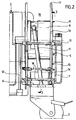
- the high-pressure cleaning device shown in the drawing 1 comprises a housing 2, which on wheels 3rd is mobile and which units 4 for suction a cleaning liquid and for dispensing it Cleaning liquid under high pressure and if necessary for heating the cleaning liquid as well as the addition of cleaning chemicals, these are known per se and therefore in the Drawing only indicated by dashed lines.
- the housing is connected to one end of the housing a receiving chamber 5 with a closed Bottom 6 and with side walls 7 that face the top and is open to the inside of the housing 2 and into the a hose reel 8 dips, which in turn one cylindrical winding core 9 and on both sides of it subsequent, radially projecting over the winding core 9 Has side walls 10.
- the hose reel 8 is at the top of the receiving chamber 5 rotatable about an axis of rotation on the receiving chamber 5 stored, which is parallel to the longitudinal direction of the Housing 2 runs, the hose reel 8 dips with its lower half into the receiving chamber 5 and protrudes from the receiving chamber with the upper half 5 out.
- a high pressure line in Formed a flexible high pressure hose 11 On the hose drum 8 is a high pressure line in Formed a flexible high pressure hose 11, the end of which dips into the winding core 9 and there via a stationary fluid coupling in the Axis of rotation of the hose reel 8 with a housing-fixed Supply line 12 is connected.
- This clutch is in not shown in the drawing, it is here is a clutch that in every position of the Hose reel connects to the housing-fixed Manufactures supply line 12.
- This supply line 12 is in turn with your pressure outlet of the units 4 in Connection, d. H. Via this supply line 12 pressurized, optionally heated and cleaning liquid with chemicals High pressure hose 11 supplied.
- the top edge 16 of this Side walls 14 are concentric with the axis of rotation the hose reel 8 at a short distance from the outer edge 17 of the circular side walls 10 of the hose reel 8, and in the area of this edge 16 of the insert 13 are parallel between the two to each other and spaced side walls 14 several webs 18 stored in parallel run longitudinally to the axis of rotation of the hose reel 8 the edge 16 and thus also along the outer edge 17 in Distance from each other and the two Side walls 14 thus together at their top connect.
- the webs 18 are only in the interior of the receiving chambers 5 arranged, so they are just the lower half of hose reel 8 directly opposite, and they span the full width the hose reel 8, so that the winding space 19 of the Hose reel 8 through the winding core 9 and Side walls 10 is defined to the outside by the Web 18 is completed.
- the webs 18 are in the side walls 14 about their longitudinal axis freely rotatable and made of metal, while the side walls 14 and thus the rest of the insert 13 are preferably made of plastic.
- the high pressure hose 11 inside the Changing room 19 held so that an unintentional Loops when unwinding, jamming between the edge of the hose reel 8 and the surrounding area, an undesirable touch of the receiving chamber 5 and wear of the high pressure hose 11 with certainty be avoided.
- the high pressure hose settles when expanding to the webs 18 and can during rotation unwind the hose reel together with these, so that sliding movements are avoided, the webs 18th continue to lead due to their thermal conductivity Cooling of the high pressure hose 11 and allow through the mutual distance the passage of Air flows that also contribute to cooling.
- the arrangement of the webs 18 on an insert 13 makes it possible to arrange such webs also in receiving chambers 5, which was originally designed without such webs were, it is enough to use them one by one 13 and then the hose reel 8 into the receiving chamber 5 to be used.
Landscapes
- Storing, Repeated Paying-Out, And Re-Storing Of Elongated Articles (AREA)
- Cleaning By Liquid Or Steam (AREA)
Applications Claiming Priority (2)
| Application Number | Priority Date | Filing Date | Title |
|---|---|---|---|
| DE29914193U | 1999-08-14 | ||
| DE29914193U DE29914193U1 (de) | 1999-08-14 | 1999-08-14 | Hochdruckreinigungsgerät |
Publications (2)
| Publication Number | Publication Date |
|---|---|
| EP1077094A1 true EP1077094A1 (fr) | 2001-02-21 |
| EP1077094B1 EP1077094B1 (fr) | 2003-01-22 |
Family
ID=8077486
Family Applications (1)
| Application Number | Title | Priority Date | Filing Date |
|---|---|---|---|
| EP00113889A Expired - Lifetime EP1077094B1 (fr) | 1999-08-14 | 2000-06-30 | Appareil de nettoyage haute pression |
Country Status (3)
| Country | Link |
|---|---|
| EP (1) | EP1077094B1 (fr) |
| DE (2) | DE29914193U1 (fr) |
| DK (1) | DK1077094T3 (fr) |
Cited By (1)
| Publication number | Priority date | Publication date | Assignee | Title |
|---|---|---|---|---|
| CN115315579A (zh) * | 2020-04-03 | 2022-11-08 | 力奇有限公司 | 紧凑型高压清洗机 |
Families Citing this family (2)
| Publication number | Priority date | Publication date | Assignee | Title |
|---|---|---|---|---|
| DE102007018250A1 (de) | 2007-04-12 | 2008-10-16 | Alfred Kärcher Gmbh & Co. Kg | Hochdruckreinigungsgerät |
| DE102008012359A1 (de) * | 2007-08-22 | 2009-02-26 | Robert Bosch Gmbh | Hochdruckreinigungsgerät |
Citations (4)
| Publication number | Priority date | Publication date | Assignee | Title |
|---|---|---|---|---|
| DE3619326A1 (de) * | 1986-06-09 | 1987-12-10 | Josef Kraenzle | Pumpeneinheit |
| EP0446653A1 (fr) * | 1990-03-08 | 1991-09-18 | MIGEN S.r.l. | Dispositif de manutention d'éléments flexibles |
| DE29809473U1 (de) * | 1998-05-26 | 1998-10-01 | Alfred Kärcher GmbH & Co, 71364 Winnenden | Hochdruckreinigungsgerät |
| EP0890394A2 (fr) * | 1997-07-10 | 1999-01-13 | Alfred Kärcher GmbH & Co. | Appareil de nettoyage à haute pression |
-
1999
- 1999-08-14 DE DE29914193U patent/DE29914193U1/de not_active Expired - Lifetime
-
2000
- 2000-06-30 DK DK00113889T patent/DK1077094T3/da active
- 2000-06-30 DE DE50001130T patent/DE50001130D1/de not_active Expired - Lifetime
- 2000-06-30 EP EP00113889A patent/EP1077094B1/fr not_active Expired - Lifetime
Patent Citations (4)
| Publication number | Priority date | Publication date | Assignee | Title |
|---|---|---|---|---|
| DE3619326A1 (de) * | 1986-06-09 | 1987-12-10 | Josef Kraenzle | Pumpeneinheit |
| EP0446653A1 (fr) * | 1990-03-08 | 1991-09-18 | MIGEN S.r.l. | Dispositif de manutention d'éléments flexibles |
| EP0890394A2 (fr) * | 1997-07-10 | 1999-01-13 | Alfred Kärcher GmbH & Co. | Appareil de nettoyage à haute pression |
| DE29809473U1 (de) * | 1998-05-26 | 1998-10-01 | Alfred Kärcher GmbH & Co, 71364 Winnenden | Hochdruckreinigungsgerät |
Cited By (1)
| Publication number | Priority date | Publication date | Assignee | Title |
|---|---|---|---|---|
| CN115315579A (zh) * | 2020-04-03 | 2022-11-08 | 力奇有限公司 | 紧凑型高压清洗机 |
Also Published As
| Publication number | Publication date |
|---|---|
| DK1077094T3 (da) | 2003-02-24 |
| EP1077094B1 (fr) | 2003-01-22 |
| DE50001130D1 (de) | 2003-02-27 |
| DE29914193U1 (de) | 1999-10-21 |
Similar Documents
| Publication | Publication Date | Title |
|---|---|---|
| EP0054212B1 (fr) | Récipient distributeur de produits pâteux | |
| DE2622041C2 (de) | Umschaltventil | |
| WO2007093467A1 (fr) | Dispositif de nettoyage conçu pour un composant d'un sèche-linge domestique | |
| CH683604A5 (de) | Schneidvorrichtung für bandförmiges Material. | |
| EP0956422B1 (fr) | Dispositif de fermeture pour ouverture murale | |
| DE69736485T2 (de) | Filtersektorvorrichtung für eine rotierende filterscheibe | |
| DE2721233B1 (de) | Aus mehreren Verdichterstufen bestehender Seitenkanalverdichter | |
| DE102012209396A1 (de) | Wasserabführungsdüse für Kühlschränke, Wasserabführungsvorrichtung und Kühlschrank | |
| EP0101544B1 (fr) | Dispositif pour accoupler une barre enrouleuse avec un arbre d'entraînement | |
| EP1077094B1 (fr) | Appareil de nettoyage haute pression | |
| DE3240027C2 (de) | Wasserablaßvorrichtung | |
| DE2124456C3 (de) | Trommeltrockner | |
| DE19829258A1 (de) | Durchlaufregal zum Kommissionieren von Lagereinheiten | |
| DE2800325A1 (de) | Vorrichtung zum steuern des durchflusses und der foerdermenge eines hydraulischen mediums in kreiselpumpen der zwillingsbauart sowie verfahren zu ihrem einbau | |
| CH630794A5 (en) | Filter device for producing aromatic extracts from coffee or tea | |
| EP2826651B1 (fr) | Cadre d'un toit coulissant de véhicule avec caniveaux de câbles | |
| EP0711589A1 (fr) | Dispositif à bandes filtrantes pour l'enlèvement de particules étrangères de bains liquides | |
| DE3917520C2 (de) | Vorrichtung zum Reinigen von Flüssigkeiten | |
| DE4420976C2 (de) | Verfahren und Vorrichtung zum kontrollierten Transport von eingedicktem Faserstoff aus einem unter Überdruck stehenden Raum | |
| EP2739858B1 (fr) | Module de filtre à air pour compresseur à canal latéral | |
| DE60102848T2 (de) | Bügelmaschine mit einer beheizten Walze und einer Wärmeträgerflüssigkeit | |
| DE2165855B2 (de) | Abdichtende Fördervorrichtung | |
| DE102004029641A1 (de) | Vorrichtung zum Filtern von Fluiden | |
| EP3575474A1 (fr) | Tambour de lavage et machine à laver | |
| DE3926472C1 (fr) |
Legal Events
| Date | Code | Title | Description |
|---|---|---|---|
| PUAI | Public reference made under article 153(3) epc to a published international application that has entered the european phase |
Free format text: ORIGINAL CODE: 0009012 |
|
| AK | Designated contracting states |
Kind code of ref document: A1 Designated state(s): CH DE DK FR IT LI |
|
| AX | Request for extension of the european patent |
Free format text: AL;LT;LV;MK;RO;SI |
|
| 17P | Request for examination filed |
Effective date: 20010202 |
|
| AKX | Designation fees paid |
Free format text: CH DE DK FR IT LI |
|
| GRAG | Despatch of communication of intention to grant |
Free format text: ORIGINAL CODE: EPIDOS AGRA |
|
| 17Q | First examination report despatched |
Effective date: 20020507 |
|
| GRAG | Despatch of communication of intention to grant |
Free format text: ORIGINAL CODE: EPIDOS AGRA |
|
| GRAH | Despatch of communication of intention to grant a patent |
Free format text: ORIGINAL CODE: EPIDOS IGRA |
|
| GRAH | Despatch of communication of intention to grant a patent |
Free format text: ORIGINAL CODE: EPIDOS IGRA |
|
| GRAA | (expected) grant |
Free format text: ORIGINAL CODE: 0009210 |
|
| AK | Designated contracting states |
Kind code of ref document: B1 Designated state(s): CH DE DK FR IT LI |
|
| REG | Reference to a national code |
Ref country code: CH Ref legal event code: EP |
|
| REG | Reference to a national code |
Ref country code: DK Ref legal event code: T3 |
|
| REF | Corresponds to: |
Ref document number: 50001130 Country of ref document: DE Date of ref document: 20030227 Kind code of ref document: P |
|
| RAP2 | Party data changed (patent owner data changed or rights of a patent transferred) |
Owner name: ALFRED KAERCHER GMBH & CO. KG |
|
| ET | Fr: translation filed | ||
| PLBE | No opposition filed within time limit |
Free format text: ORIGINAL CODE: 0009261 |
|
| STAA | Information on the status of an ep patent application or granted ep patent |
Free format text: STATUS: NO OPPOSITION FILED WITHIN TIME LIMIT |
|
| 26N | No opposition filed |
Effective date: 20031023 |
|
| PG25 | Lapsed in a contracting state [announced via postgrant information from national office to epo] |
Ref country code: CH Free format text: LAPSE BECAUSE OF NON-PAYMENT OF DUE FEES Effective date: 20040630 Ref country code: LI Free format text: LAPSE BECAUSE OF NON-PAYMENT OF DUE FEES Effective date: 20040630 |
|
| REG | Reference to a national code |
Ref country code: CH Ref legal event code: PL |
|
| PGFP | Annual fee paid to national office [announced via postgrant information from national office to epo] |
Ref country code: DK Payment date: 20130611 Year of fee payment: 14 |
|
| PGFP | Annual fee paid to national office [announced via postgrant information from national office to epo] |
Ref country code: FR Payment date: 20130624 Year of fee payment: 14 Ref country code: IT Payment date: 20130618 Year of fee payment: 14 |
|
| PGFP | Annual fee paid to national office [announced via postgrant information from national office to epo] |
Ref country code: DE Payment date: 20130730 Year of fee payment: 14 |
|
| REG | Reference to a national code |
Ref country code: DE Ref legal event code: R119 Ref document number: 50001130 Country of ref document: DE |
|
| REG | Reference to a national code |
Ref country code: DK Ref legal event code: EBP Effective date: 20140630 |
|
| REG | Reference to a national code |
Ref country code: DE Ref legal event code: R119 Ref document number: 50001130 Country of ref document: DE Effective date: 20150101 |
|
| REG | Reference to a national code |
Ref country code: FR Ref legal event code: ST Effective date: 20150227 |
|
| PG25 | Lapsed in a contracting state [announced via postgrant information from national office to epo] |
Ref country code: DE Free format text: LAPSE BECAUSE OF NON-PAYMENT OF DUE FEES Effective date: 20150101 Ref country code: IT Free format text: LAPSE BECAUSE OF NON-PAYMENT OF DUE FEES Effective date: 20140630 |
|
| PG25 | Lapsed in a contracting state [announced via postgrant information from national office to epo] |
Ref country code: FR Free format text: LAPSE BECAUSE OF NON-PAYMENT OF DUE FEES Effective date: 20140630 |
|
| PG25 | Lapsed in a contracting state [announced via postgrant information from national office to epo] |
Ref country code: DK Free format text: LAPSE BECAUSE OF NON-PAYMENT OF DUE FEES Effective date: 20140630 |