EP1077105B1 - Vorrichtung zum Feinschleifen von Stirnflächen an dünnwandigen und/oder kleinstückigen Serienteilen - Google Patents
Vorrichtung zum Feinschleifen von Stirnflächen an dünnwandigen und/oder kleinstückigen Serienteilen Download PDFInfo
- Publication number
- EP1077105B1 EP1077105B1 EP19990112215 EP99112215A EP1077105B1 EP 1077105 B1 EP1077105 B1 EP 1077105B1 EP 19990112215 EP19990112215 EP 19990112215 EP 99112215 A EP99112215 A EP 99112215A EP 1077105 B1 EP1077105 B1 EP 1077105B1
- Authority
- EP
- European Patent Office
- Prior art keywords
- workpiece
- driver
- rotation
- thin
- supporting ring
- Prior art date
- Legal status (The legal status is an assumption and is not a legal conclusion. Google has not performed a legal analysis and makes no representation as to the accuracy of the status listed.)
- Expired - Lifetime
Links
Images

Classifications
-
- B—PERFORMING OPERATIONS; TRANSPORTING
- B24—GRINDING; POLISHING
- B24B—MACHINES, DEVICES, OR PROCESSES FOR GRINDING OR POLISHING; DRESSING OR CONDITIONING OF ABRADING SURFACES; FEEDING OF GRINDING, POLISHING, OR LAPPING AGENTS
- B24B7/00—Machines or devices designed for grinding plane surfaces on work, including polishing plane glass surfaces; Accessories therefor
- B24B7/10—Single-purpose machines or devices
- B24B7/16—Single-purpose machines or devices for grinding end-faces, e.g. of gauges, rollers, nuts, piston rings
- B24B7/162—Single-purpose machines or devices for grinding end-faces, e.g. of gauges, rollers, nuts, piston rings for mass articles
-
- B—PERFORMING OPERATIONS; TRANSPORTING
- B24—GRINDING; POLISHING
- B24B—MACHINES, DEVICES, OR PROCESSES FOR GRINDING OR POLISHING; DRESSING OR CONDITIONING OF ABRADING SURFACES; FEEDING OF GRINDING, POLISHING, OR LAPPING AGENTS
- B24B33/00—Honing machines or devices; Accessories therefor
- B24B33/02—Honing machines or devices; Accessories therefor designed for working internal surfaces of revolution, e.g. of cylindrical or conical shapes
Definitions
- the invention relates to a device for fine grinding from end faces to thin-walled and / or small pieces Series parts. It can with the workpieces to be machined are sleeves, rings and the like, the Front face need precision machining.
- the In particular, the device should also be usable for Processing of micro housings for electronic components, z. B. for processing a trained as a membrane End face on housings for pressure sensors, as well as for Machining end faces on small valve housings, z. B. of fuel injectors.
- a radial clamping of small pieces, the a diameter and a length of a few millimeters can be difficult. There is a risk of Centering errors due to tilting and the like. at thin-walled components there is the risk that the Workpieces through those exerted by a clamping device radial clamping forces are deformed.
- the invention has for its object a device for fine grinding end faces on thin-walled and / or to specify on small-scale series parts, in which one exact centering of the workpiece is guaranteed and radial clamping forces on the workpiece to be machined are not be exercised.
- the Support ring mounted on an annular piston, which in a annular and pressurizable with a pressure medium Chamber of the workpiece carrier inserted and against rotation is secured.
- the Ring piston a tensioning movement towards the driver out.
- the span is limited by a stop.
- a roller bearing arranged between the support ring and the ring piston.
- the invention teaches that the Workpiece carrier with several identically designed Workpiece holder is equipped, which are successively through a movement of the workpiece carrier in the work area can be inserted between driver and grinding tool.
- the workpiece carrier travel are useful Equipment for loading the workpiece holders with Workpieces and machined for removal Workpieces provided so that the loading, removal and Machining workpieces can be performed simultaneously can.
- the tool carrier is preferably a transport disk with star-shaped workpiece holders trained, the workpiece holders by radial Fluid channels can be acted upon with a pressure medium.
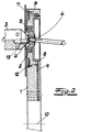
- FIG. 1 shows a section of a longitudinal section Device for fine grinding end faces small piece serial parts.
- Fig. 1 is the processing of an end membrane surface a miniature housing for pressure sensors shown.
- 2 shows the processing of a conical seat of a valve housing for a Fuel injection valve. In both figures it is Workpiece shown greatly enlarged.
- Device For the basic structure of those shown in the figures Device include a workpiece holder 1 with at least a workpiece holder 2, a rotatingly drivable Driver 3 and a rotating drivable grinding tool 4.
- the workpiece holder 2 has a rotatable supported support ring 5, in which to be machined Workpiece 6 can be used.
- the support ring 5 is on one Ring piston 7 stored in an annular and with chamber 8 of the workpiece carrier which can be acted upon by a pressure medium 1 is inserted and secured against rotation. By pressurizing the chamber 8 Ring piston 7 an axial clamping movement, which Workpiece 6 between the driver 3 and the support ring 5 can be clamped.
- the workpiece 6 to be machined on its end face facing away from a collar on between the driver 3 and the support ring 5th can be clamped.
- a workpiece 6 is machined, the end on a collar of the support ring 5 axially is supported.
- the workpiece carrier 1 is in the embodiments with several star-shaped workpiece holders 2 educated. All workpiece holders are identical in the described way built up and successively by a Rotary movement of the workpiece carrier 1 in the work area can be inserted between driver 3 and grinding tool 4. By radial fluid channels 9 are the workpiece holders 2 with pressurized with a pressure medium.
- the workpiece carrier 1 rotates a horizontal axis of rotation 10.
- an annular guide plate 11 intended.
- the span of the annular piston 7 is through a Circlip 12 limited as a stop. Also recognizes one that the driver 3 with an interchangeable driver insert 13 is equipped.
- Grinding tool 4 from a rotatingly driven Cup wheel.
- the machined area is used during the Processing scanned by a measuring device 14. Is this Finished dimension between flange surface and machined surface reached, the grinding process is finished.
- the grinding tool 4 When machining the workpiece shown in Fig. 2 6, the grinding tool 4 consists of a rotating driven cylindrical grindstone, which in the Workpiece 6 is insertable.
- the axis of rotation of the Whetstone is below one in the embodiment small angle at an angle to the axis of rotation of the support ring 5 aligned.
- With the tool arrangement is in the conical seat of the workpiece an annular, in the form of an arcuate depression as Seat for a valve ball incorporated.
Landscapes
- Engineering & Computer Science (AREA)
- Mechanical Engineering (AREA)
- Physics & Mathematics (AREA)
- Geometry (AREA)
- Grinding Of Cylindrical And Plane Surfaces (AREA)
- Finish Polishing, Edge Sharpening, And Grinding By Specific Grinding Devices (AREA)
- Constituent Portions Of Griding Lathes, Driving, Sensing And Control (AREA)
Description
Claims (5)
- Vorrichtung zum Feinschleifen von Stirnflächen an dünnwandigen und/oder kleinstückigen Serienteilen, mitwobei die Werkstückaufnahme (2) einen drehbeweglich gelagerten Stützring (5) aufweist, in den das zu bearbeitende Werkstück (6) einsetzbar ist, und wobei das Werkstück (6) durch eine Stellbewegung des Treibers (3) oder der Werkstückaufnahme (2) axial zwischen dem Treiber (3) und dem Stützring (5) einspannbar ist.einem Werkstückträger (1) mit mindestens einer Werkstückaufnahme (2),einem rotierend antreibbaren Treiber (3) undeinem rotierend antreibbaren Schleifwerkzeug (4),
- Vorrichtung nach Anspruch 1, dadurch gekennzeichnet, daß der Stützring (5) an einem Ringkolben (7) gelagert ist, der in eine ringförmige und mit einem Druckmedium beaufschlagbare Kammer (8) des Werkstückträgers (1) eingesetzt und gegen Drehung gesichert ist.
- Vorrichtung nach Anspruch 2, dadurch gekennzeichnet, daß zwischen dem Stützring (5) und dem Ringkolben (7) ein Wälzlager angeordnet ist.
- Vorrichtung nach einem der Ansprüche 1 bis 3, dadurch gekennzeichnet, daß der Werkstückträger (1) mit mehreren identisch ausgebildeten Werkstückaufnahmen (2) ausgerüstet ist, die nacheinander durch eine Bewegung des Werkstückträgers (1) in den Arbeitsbereich zwischen Treiber (3) und Schleifwerkzeug (4) einbringbar sind.
- Vorrichtung nach Anspruch 4, dadurch gekennzeichnet, daß der Werkstückträger (1) als Transportscheibe mit sternförmig angeordneten Werkstückaufnahmen (2) ausgebildet ist und daß die Werkstückaufnahmen (2) durch radiale Fluidkanäle (9) mit einem Druckmedium beaufschlagbar sind.
Priority Applications (2)
| Application Number | Priority Date | Filing Date | Title |
|---|---|---|---|
| EP19990112215 EP1077105B1 (de) | 1999-06-25 | 1999-06-25 | Vorrichtung zum Feinschleifen von Stirnflächen an dünnwandigen und/oder kleinstückigen Serienteilen |
| DE59901121T DE59901121D1 (de) | 1999-06-25 | 1999-06-25 | Vorrichtung zum Feinschleifen von Stirnflächen an dünnwandigen und/oder kleinstückigen Serienteilen |
Applications Claiming Priority (1)
| Application Number | Priority Date | Filing Date | Title |
|---|---|---|---|
| EP19990112215 EP1077105B1 (de) | 1999-06-25 | 1999-06-25 | Vorrichtung zum Feinschleifen von Stirnflächen an dünnwandigen und/oder kleinstückigen Serienteilen |
Publications (2)
| Publication Number | Publication Date |
|---|---|
| EP1077105A1 EP1077105A1 (de) | 2001-02-21 |
| EP1077105B1 true EP1077105B1 (de) | 2002-04-03 |
Family
ID=8238419
Family Applications (1)
| Application Number | Title | Priority Date | Filing Date |
|---|---|---|---|
| EP19990112215 Expired - Lifetime EP1077105B1 (de) | 1999-06-25 | 1999-06-25 | Vorrichtung zum Feinschleifen von Stirnflächen an dünnwandigen und/oder kleinstückigen Serienteilen |
Country Status (2)
| Country | Link |
|---|---|
| EP (1) | EP1077105B1 (de) |
| DE (1) | DE59901121D1 (de) |
Family Cites Families (3)
| Publication number | Priority date | Publication date | Assignee | Title |
|---|---|---|---|---|
| DE879523C (de) * | 1942-11-28 | 1953-06-15 | Messerschmitt Boelkow Blohm | Verfahren und Vorrichtung zum Laeppen von Werkstuecken, insbesondere von Bohrungen |
| DE3338811A1 (de) * | 1983-10-26 | 1985-05-09 | Sinterstahl GmbH, 8958 Füssen | Verfahren zum schleifen von praezisionsteilen |
| CA2061001C (en) * | 1991-04-15 | 1993-11-30 | Calvin H. Taylor | Method of apparatus for grinding the end of a tubular workpiece |
-
1999
- 1999-06-25 EP EP19990112215 patent/EP1077105B1/de not_active Expired - Lifetime
- 1999-06-25 DE DE59901121T patent/DE59901121D1/de not_active Expired - Fee Related
Also Published As
| Publication number | Publication date |
|---|---|
| EP1077105A1 (de) | 2001-02-21 |
| DE59901121D1 (de) | 2002-05-08 |
Similar Documents
| Publication | Publication Date | Title |
|---|---|---|
| DE19857359B4 (de) | Verfahren und Vorrichtung zum Bearbeiten von Werkstücken mit dünnwandigen Bereichen, die zentrische Formabweichungen aufweisen | |
| DE102010036445B4 (de) | Vorrichtung zur Aufnahme von ringförmigen Werkstücken und Finishmaschinen mit dieser Vorrichtung | |
| DE4009571C2 (de) | ||
| EP0322710A2 (de) | Lagerung für Hochgeschwindigkeits-Spindeln von Werkzeugmaschinen | |
| DE1752520C3 (de) | Schleifmaschine für ringförmige Werkstücke | |
| DE1752064C3 (de) | Feinschleifmnaschine zum Schleifen der Innnenseiten von ringförmigen Werkstücken, insbesondere Kugellagerungen | |
| EP0482397A2 (de) | Verfahren und Vorrichtung zum Feinschleifen von Ringen auf der Ringaussenfläche oder auf der Ringinnenfläche | |
| EP1077105A1 (de) | Vorrichtung zum Feinschleifen von Stirnflächen an dünnwandigen und/oder kleinstückigen Serienteilen | |
| DE4131752A1 (de) | Verfahren zum einseitigen flaechenbearbeiten von werkstuecken | |
| DE1937802C3 (de) | Schleifmaschine für ringförmige Werkstücke | |
| DE650471C (de) | Vorrichtung zum Auswalzen | |
| DE961060C (de) | Maschine zur Innenbearbeitung gewoelbter Kesselboeden | |
| DE19951034A1 (de) | Verfahren zum Sichern einer Schleifhülse an einer Aufspannvorrichtung und Aufspannvorrichtung für Schleifhülsen | |
| DE889718C (de) | Verfahren zur spanabhebenden Bearbeitung von Zapfen an genau rund geschliffenen zylindrischen Werkstuecken | |
| DE3635973A1 (de) | Vorrichtung zum aufspannen von hochgeschwindigkeitsschleifscheiben | |
| DE3639871A1 (de) | Spanndorn bzw. spannfutter mit selbsttaetiger und zwangslaeufiger zentrierung manuell und automatisch mit grossem spannbereich | |
| DE1805307C3 (de) | Schleifmaschine für ringförmige Werkstücke | |
| DE2407261C3 (de) | Vorrichtung für die schleifende Bearbeitung der ebenen Stirnfläche an einem im übrigen hohlzylindrischen Werkstück | |
| EP4149717B1 (de) | Vorrichtung und verfahren zum schleifen und honen sowie verwendung der vorrichtung | |
| DE3704722C2 (de) | ||
| DE3027445C2 (de) | Feinschleifmaschine für hohlzylindrische Werkstücke | |
| EP2321091A1 (de) | Vorrichtung und verfharen zur bearbeitung eines lagersitzes oder eines darin gelagerten lagerzapfens | |
| DE2912814A1 (de) | Schleifvorrichtung | |
| DE3327579C2 (de) | ||
| DE102021115296A1 (de) | Schleifvorrichtung zum Schleifen eines kugelförmigen Werkstücks und Verfahren |
Legal Events
| Date | Code | Title | Description |
|---|---|---|---|
| PUAI | Public reference made under article 153(3) epc to a published international application that has entered the european phase |
Free format text: ORIGINAL CODE: 0009012 |
|
| 17P | Request for examination filed |
Effective date: 20000504 |
|
| AK | Designated contracting states |
Kind code of ref document: A1 Designated state(s): DE ES FR GB IT |
|
| AX | Request for extension of the european patent |
Free format text: AL;LT;LV;MK;RO;SI |
|
| RTI1 | Title (correction) |
Free format text: APPARATUS TO FINISH-GRIND THE END FACES OF SMALL AND/OR THIN-WALLED MASS-PRODUCED PARTS |
|
| GRAG | Despatch of communication of intention to grant |
Free format text: ORIGINAL CODE: EPIDOS AGRA |
|
| GRAG | Despatch of communication of intention to grant |
Free format text: ORIGINAL CODE: EPIDOS AGRA |
|
| GRAH | Despatch of communication of intention to grant a patent |
Free format text: ORIGINAL CODE: EPIDOS IGRA |
|
| RIN1 | Information on inventor provided before grant (corrected) |
Inventor name: WOLTERS, MARTIN Inventor name: MUELLER, MICHAEL Inventor name: LOOCK, MANFRED |
|
| 17Q | First examination report despatched |
Effective date: 20010912 |
|
| AKX | Designation fees paid |
Free format text: DE ES FR GB IT |
|
| GRAH | Despatch of communication of intention to grant a patent |
Free format text: ORIGINAL CODE: EPIDOS IGRA |
|
| REG | Reference to a national code |
Ref country code: GB Ref legal event code: IF02 |
|
| GRAA | (expected) grant |
Free format text: ORIGINAL CODE: 0009210 |
|
| AK | Designated contracting states |
Kind code of ref document: B1 Designated state(s): DE ES FR GB IT |
|
| REF | Corresponds to: |
Ref document number: 59901121 Country of ref document: DE Date of ref document: 20020508 |
|
| GBT | Gb: translation of ep patent filed (gb section 77(6)(a)/1977) |
Effective date: 20020702 |
|
| ET | Fr: translation filed | ||
| PG25 | Lapsed in a contracting state [announced via postgrant information from national office to epo] |
Ref country code: ES Free format text: LAPSE BECAUSE OF FAILURE TO SUBMIT A TRANSLATION OF THE DESCRIPTION OR TO PAY THE FEE WITHIN THE PRESCRIBED TIME-LIMIT Effective date: 20021030 |
|
| PLBE | No opposition filed within time limit |
Free format text: ORIGINAL CODE: 0009261 |
|
| STAA | Information on the status of an ep patent application or granted ep patent |
Free format text: STATUS: NO OPPOSITION FILED WITHIN TIME LIMIT |
|
| 26N | No opposition filed |
Effective date: 20030106 |
|
| PGFP | Annual fee paid to national office [announced via postgrant information from national office to epo] |
Ref country code: GB Payment date: 20030616 Year of fee payment: 5 |
|
| PGFP | Annual fee paid to national office [announced via postgrant information from national office to epo] |
Ref country code: DE Payment date: 20030618 Year of fee payment: 5 |
|
| PGFP | Annual fee paid to national office [announced via postgrant information from national office to epo] |
Ref country code: FR Payment date: 20030630 Year of fee payment: 5 |
|
| PG25 | Lapsed in a contracting state [announced via postgrant information from national office to epo] |
Ref country code: GB Free format text: LAPSE BECAUSE OF NON-PAYMENT OF DUE FEES Effective date: 20040625 |
|
| PG25 | Lapsed in a contracting state [announced via postgrant information from national office to epo] |
Ref country code: DE Free format text: LAPSE BECAUSE OF NON-PAYMENT OF DUE FEES Effective date: 20050101 |
|
| GBPC | Gb: european patent ceased through non-payment of renewal fee |
Effective date: 20040625 |
|
| PG25 | Lapsed in a contracting state [announced via postgrant information from national office to epo] |
Ref country code: FR Free format text: LAPSE BECAUSE OF NON-PAYMENT OF DUE FEES Effective date: 20050228 |
|
| REG | Reference to a national code |
Ref country code: FR Ref legal event code: ST |
|
| PG25 | Lapsed in a contracting state [announced via postgrant information from national office to epo] |
Ref country code: IT Free format text: LAPSE BECAUSE OF NON-PAYMENT OF DUE FEES Effective date: 20050625 |