EP1077112A2 - Vorrichtung zum Spannen von Werkstücken - Google Patents
Vorrichtung zum Spannen von Werkstücken Download PDFInfo
- Publication number
- EP1077112A2 EP1077112A2 EP00114959A EP00114959A EP1077112A2 EP 1077112 A2 EP1077112 A2 EP 1077112A2 EP 00114959 A EP00114959 A EP 00114959A EP 00114959 A EP00114959 A EP 00114959A EP 1077112 A2 EP1077112 A2 EP 1077112A2
- Authority
- EP
- European Patent Office
- Prior art keywords
- base element
- clamping
- workpiece
- piston
- workpieces
- Prior art date
- Legal status (The legal status is an assumption and is not a legal conclusion. Google has not performed a legal analysis and makes no representation as to the accuracy of the status listed.)
- Granted
Links
Images


Classifications
-
- B—PERFORMING OPERATIONS; TRANSPORTING
- B25—HAND TOOLS; PORTABLE POWER-DRIVEN TOOLS; MANIPULATORS
- B25B—TOOLS OR BENCH DEVICES NOT OTHERWISE PROVIDED FOR, FOR FASTENING, CONNECTING, DISENGAGING, OR HOLDING
- B25B11/00—Work holders not covered by any preceding group in the subclass, e.g. magnetic work holders, vacuum work holders
- B25B11/005—Vacuum work holders
- B25B11/007—Vacuum work holders portable, e.g. handheld
-
- B—PERFORMING OPERATIONS; TRANSPORTING
- B25—HAND TOOLS; PORTABLE POWER-DRIVEN TOOLS; MANIPULATORS
- B25B—TOOLS OR BENCH DEVICES NOT OTHERWISE PROVIDED FOR, FOR FASTENING, CONNECTING, DISENGAGING, OR HOLDING
- B25B5/00—Clamps
- B25B5/06—Arrangements for positively actuating jaws
- B25B5/061—Arrangements for positively actuating jaws with fluid drive
Definitions
- the invention relates to a device for tensioning Workpieces for cutting or non-cutting processing.
- Plastics, light metals or wood substitutes belongs to a machine tool with at least three perpendicular axes of the X, Y and Z axes, movable machining head.
- the workpieces as a rule plate-like or strip-like, are on corresponding Machining stations adjusted so that a collision of the Adjustment and holding device with the Machining tools is excluded as far as possible.
- Vacuum clamping devices To the mostly plate-shaped workpieces in any Position in the X, Y machining plane of the machine tool to adjust and hold are so-called Vacuum clamping devices used.
- This Vacuum clamping devices generally as vacuum blocks or Suction clamps include one or more Basic elements that have a lower, marginal on their underside Sealed suction field for fixing on the top of a Have workpiece space on a machine tool. At hers The top is also an edge sealed suction field provided that serves for suction clamping of the workpieces.
- suction clamps are usually two vacuum lines connectable, one of which is connected to the upper one Suction field and the other connected to the lower suction field becomes.
- the flexible arrangement of the suction clamps enables that workpieces of any geometry along their edges can be edited and the whole Workpiece clamping device is not damaged. Further is the workpiece is easily accessible all around.
- Such vacuum chucks are known in the art for the workpiece location of a machine tool, in particular for Processing of plate-shaped workpieces made of wood or woody materials, well known.
- the suction clamps are thereby parallel to each other, transversely towards one of the Machining axes, e.g. the X axis, adjustable bars in Positioned in the direction of the Y axis.
- the plate-shaped Workpieces are attached to the upper suction field attached to the upper, accessible side of the suction clamp.
- German patent DE 44 04 513 C1 there is one described such a vacuum chuck in which the Vacuum lines in the area of the workpiece support safely and are arranged trouble-free. These are in the bars in Two vacuum channels arranged in the longitudinal direction and each of these Vacuum channels with a longitudinal row of suction openings on the Top of the respective bar via flow valves connected. Compared to other systems that supply vacuum Use flexible hoses is by the in the DE 44 04 413 C1 described a configuration Clamping device for plate-shaped workpieces created, which have largely trouble-free access to the workpiece enables.
- the invention has for its object a device for clamping workpieces that create the safe Clamping of strip-shaped work pieces enables and at the same time, secure and trouble-free accessibility guaranteed.
- the invention is based on the idea of taking advantage of positionable suction clamps when machining to use strip-like workpieces.
- the basic element which has a lower, edge sealed suction field for fixation on the Top of a beam or on the workpiece position of one Has machine tool, integrated a piston assembly.
- This piston arrangement is with a for clamping strip-like workpieces made of wood, plastics, wood-like materials or light metals Furnishings.
- the piston arrangement is like this designed that a workpiece between the in the installed position upper end of the piston assembly and the top of the Basic element can be tensioned.
- This combination of vacuum clamping device and device for clamping strips offers the advantages of Vacuum clamping devices for plate-shaped components are known are, also for strip-shaped components. So they can Suction clamps flexible at any point on the Workpiece rest can be arranged, which is a good one Accessibility to the workpiece for machining, e.g. Milling, sawing, drilling, or non-cutting processing, e.g. Bending, gluing or the like.
- the Clamping device can also be positioned quickly and safely against slipping on the workpiece position Attach machine tool.
- the device for clamping workpieces after one advantageous embodiment a piston arrangement in such a way that the underside of the Piston arrangement with the side walls of the base element and the bottom wall of the base element an evacuable cavity forms.
- This embodiment has the advantage that the Piston arrangement is movable by evacuating the cavity.
- the vacuum supply to evacuate the cavity in the floor area of the Basic element attached.
- the positioning of the Vacuum supply e.g. consists of hoses, near the Workpiece space and as far as possible from the Workpiece clamping level causes a largely undisturbed Accessibility to the workpiece.
- the vacuum supply for evacuating the Cavity through the bottom wall of the base element A Vacuum supply through the bottom wall of the base element and further through correspondingly provided vacuum channels in the bars of the Workpiece space avoid impairing the Accessibility to the workpiece through vacuum hoses or similar completely.
- the chip removal in case of cutting Editing is also not hindered by this.
- Suction openings and obstructing or blocking the air inlet Flow valves can be used without retrofitting continue to be used.
- the device for tensioning advantageously has Workpieces at least two separately switchable Vacuum circles.
- Two separately switchable vacuum circuits can suction and attach the suction clamp done in a first step and the positioning of the Workpiece on the device is independent of the Attachment of the suction clamp and can be done in a separate Work step happen.
- the device for clamping workpieces on the suction clamp Clamp is well known in the art Devices to secure components of various geometries to hold on. Last-shaped components can go through Clamping claws can also be attached well.
- the clamping claw is preferably on the piston arrangement rotatably attached. This in turn serves a larger one Flexibility in positioning the workpiece.
- the clamping claw is advantageously asymmetrical educated.
- the more suitable part of the clamping claw selected for tensioning and the other part unused or two workpieces can remain at the same time, too different geometries.
- the Clamping claw two clamping legs of different lengths.
- two clamping legs are two workpieces can be clamped and edited at the same time, whereby by a different length of the clamping leg is achieved that depending on the geometry of the workpiece or workpieces the appropriate clamping leg assigned to the workpiece can be held and thus the workpiece is held very securely becomes.
- the clamping claw is advantageously on its underside provided with an elastic coating. This Coating prevents the workpiece from slipping and reduces the risk of damage to the workpiece hard parts of the clamping device.
- the device for tensioning comprises Workpieces a return spring for the piston assembly.
- a return spring for the piston assembly is the Clamping device when the vacuum circuit to move the Piston assembly is not active in an open state held. This means that workpieces can be easily inserted into the Clamping device can be inserted or from it can be removed.
- the device for tensioning preferably comprises Workpieces at least one adjustment stop for the Workpiece.
- Such an adjustment stop has the advantage that workpieces that are on their unworkable side for example, tiered, lighter and firmer can be.
- the adjustment stop is preferably for the workpiece releasably on the device for clamping Workpieces attached. This enables that depending on a suitable geometry of the workpiece to be machined Adjustment stop can be selected and used.
- Basic element essentially made of plastic.
- the usage of plastic for the basic element enables a inexpensive manufacture of the basic element and also offers the advantage that the risk of damage to the Machine tool or the tool at one unintentional collision with the basic element far is less than with harder materials, such as Steel.
- the stand has of the basic element one or more adjustment stops.
- This Adjustment stops serve for exact alignment of the Basic element. When using such adjustment stops only the adjustment stops have to be made extremely accurately to ensure precise alignment of the basic element on the Ensure machine tool. This offers one Price advantage over the adjustment by means of larger ones Areas of the actual floor area of the base element that then must be made to fit overall.
- the base element preferably has the workpiece facing surface has a ventilation opening.
- This Ventilation opening serves to equalize the pressure at the Evacuation through the bottom wall, the side walls of the Basic element and the piston limited cavity.
- a positioning aid is advantageously on the basic element attached for the basic element. This positioning aid facilitates the positioning of the basic element on the Workplace location of a machine tool.
- the Piston arrangement of a piston rod and one Piston plate The structure of the piston assembly from the piston rod and piston plate allows different geometries of the Basic element by adapting the shape of the piston plate can be used.
- the piston rod can act as a stop be used for the workpiece and takes the actual one Clamping device on.
- the piston plate serves the Sealing of the base plate by base plate, Side walls of the base element and piston arrangement defined Cavity that is suitable for evacuation.
- sealing arrangement for sealing against the side walls of the basic element attached.
- the sealing arrangement is like this trained that on the one hand they slide the Piston arrangement along the base element allows on the other hand for reliable sealing of the evacuable cavity.
- one conventional sealing arrangement e.g. an O-ring, allows for a seal through for example, good tolerance tolerance inexpensive sealing of the cavity.
- the device for tensioning preferably comprises Workpieces a guide element for the piston rod.
- a guide element becomes the danger of tilting or Reduced twisting of the piston rod and a one-sided Clamping a workpiece in the arrangement allows.
- the guidance of the piston rod can accommodate the Return spring for the piston assembly.
- the guide element is advantageously for the Piston rod in the evacuable cavity of the basic element attached. This offers the advantage of a compact design the arrangement and also the lowest possible Impairment of accessibility to the work to be done Workpiece.
- Fig. 1 is a first embodiment of the device for Clamping workpieces 50 shown, two different workpieces 33, 34 are clamped.
- the device comprises a basic element 10, which has a Bottom wall 17 on the footprint 32 in the workpiece position can be attached.
- the attachment of the base element 10 for machining on the workpiece position of a machine tool or non-cutting machining of workpieces, e.g. Drill, Milling, sawing or gluing and bending takes place at the illustrated embodiment of the basic element via a Row of suction openings on top of a beam the workpiece location of a machine tool, which with the Vacuum devices 31 in the bottom area of the base element interact.
- the vacuum supply 19 to the suction openings in Workpiece space that corresponds to a first vacuum circuit shown schematically.
- This basic element can be in one another embodiment (not shown) instead of directly via suction openings with valves on the beams of the Machine tool to be evacuable, also from the side attached hoses are evacuated. However, arises then some interference from the hoses Accessibility to the workpiece.
- the base element 10 is shown in FIG Embodiment a positioning aid 28 attached.
- This Positioning aid serves to put the basic element on for this provided bar of the workpiece location Align machine tool in X, Y plane. This Operation can either be done by hand or under Using robots.
- the basic element 10 is by means of the adjustment stops 27 on the workpiece position Machine tool aligned with the horizontal.
- Piston arrangement 13 In this basic element 10, which in the technical language with Suction clamp or vacuum block is one Piston arrangement 13 integrated.
- the piston assembly 13 is made from a piston rod 14 and a piston plate 15. Die Piston rod 14 is in the installed position through an opening Out top of the base element.
- the piston plate 15 is designed so that they essentially the geometry of the Floor area of the base element 10 corresponds and thus a Type partition between the bottom wall of the base element 10 and creates the upper wall of the base element 10.
- evacuable cavity 11 is on the side surface the piston plate 15 all around a sealing device 30 appropriate.
- the sealing device 30 can, for example, be a Rubber seal, like an O-ring. It can of course, any other standard in technology Seal are used, which is simultaneously a sliding of the Piston plate 15 along the side wall of base member 10 enables.
- a return spring 25 is attached in the guide device 12 for the piston device 13 .
- This return spring 25 acts so that the piston assembly 13 of the Return spring is held in a position by this is characterized in that the distance between the top of the Piston device 13 and top of base element 10 is larger than a workpiece 33, 34 to be machined.
- a Fastener 16 for example a conventional one Can be screw, a clamping claw 20 attached.
- the Fastening element 16 is advantageously designed that the clamping claw 20 in any angular position can be fixed and therefore extremely flexible with regard to of clamping the workpiece. Clamp securely around workpieces to be able to have the clamping claw preferably on her Underside of an elastic coating 21. This elastic Coating serves to prevent the workpiece 33, 34 from slipping largely excluded and also the workpiece against To protect damage from the clamping claw.
- the clamping claw shown in Fig. 1 is asymmetrical trained and has a shorter clamping leg 22 and a longer clamping leg 23. This design increases the Flexibility in configuration and geometry of the Workpieces 33, 34.
- 34 includes the device further includes one or more adjustment stops for the workpiece or the workpieces.
- This adjustment stop 29 is not fixed to the base element 10 or Piston device 13 connected. That enables one easy replacement of the adjustment stop 29 depending on the Geometry of the workpiece 33.
- the base element 10 comprises a ventilation opening 26.
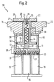
- Fig. 2 is a similar device for tensioning Workpieces as shown in Fig. 1.
- the vacuum supply too through the bottom wall and side walls of the base element 10 as well as piston plate 15 defined cavity is so designed to pass through the bottom wall of base member 10 runs through and on the footprint 32 of the Basic element 10 with suction openings on the top of a Bar on the workpiece location of a machine tool interacts, and so the connection between vacuum supply 18 and evacuable cavity 11 is produced. Thereby hoses on the workpiece table are completely eliminated.
- Fig. 3 is a plan view of a device for Clamping workpieces as shown in Fig. 1 or 2 is presented, layed out.
- the clamp 20 is in any Angular position by the fastener 16, about one Screw, adjustable. This enables great flexibility when clamping a workpiece.
- the Suction clamp which is essentially the base element 10 corresponds to a designated place on one Bars of a workpiece location of a machine tool is aligned with the aid of the adjusting devices 27, 28. Then a first vacuum circuit is activated so that the base element 10 through the vacuum spaces 31 and Vacuum feeder 19 on the workpiece position Machine tool is fixed. The exact positioning of the Basic element 10 in the X, Y plane happens beforehand via the Positioning aid 28.
- a Vacuum supply 18, 24 activated a second vacuum circuit, so that through the bottom wall of the base element, the side walls of the base element 10 and the piston plate 15 formed Cavity is evacuated.
- the vacuum in evacuated room 11 is ensured unintentional loosening of the workpiece, that too strip-shaped workpiece can be excluded.
- the vacuum is evacuated Cavity 11 deactivated via the feed devices 18, 24, the spring force of the return spring 25 can thus Piston device 13 and the clamping claw 20 upwards press and the workpiece can be removed from the device become.
- Clamping workpieces lies in the fact that also strip-shaped Components can be clamped, and still the advantages the clamping of workpieces with suction clamps remain, especially the good accessibility to the workpiece.
- the embodiment is completely tubeless and therefore very flexible. The machining resulting chips can also not be in the hoses Caught for delivery to the evacuation units.
- the system offers a high level of security with regard to the Fastening of the workpieces, since a vacuum query is possible Can easily and reliably determine faults. This in turn reduces the risk of accidents.
Landscapes
- Engineering & Computer Science (AREA)
- Mechanical Engineering (AREA)
- Jigs For Machine Tools (AREA)
- Physical Vapour Deposition (AREA)
Abstract
Description
- Fig. 1.
- ein Schnitt durch die erfindungsgemäße Vorrichtung zum Spannen von Werkstücken ist;
- Fig. 2
- ein Schnitt durch die Vorrichtung zum Spannen von Werkstücken in einer zweiten Ausführungsform ist; und
- Fig. 3
- eine Draufsicht auf die Vorrichtung zum Spannen von Werkstücken ist.
Claims (21)
- Vorrichtung zum Spannen von Werkstücken (50) für spanende oder spanlose Bearbeitung, umfassend: ein Grundelement (10), das durch eine Vakuumspannvorrichtung (19) auf einer Arbeitsfläche befestigbar ist;
dadurch gekennzeichnet, dassim Grundelement (10) eine Kolbenanordnung angebracht ist, derart dass ein Element der Kolbenanordnung (13) in Einbaulage über die Oberseite des Grundelements (10) in ausgefahrenem Zustand der Kolbenanordnung (13) vorsteht; undan dem im ausgefahrenen Zustand der Kolbenanordnung (13) über die Oberseite des Grundelements (10) vorstehenden Element der Kolbenanordnung (13) eine Einrichtung zum Spannen von Werkstücken angebracht ist. - Vorrichtung nach Anspruch 1,
dadurch gekennzeichnet, dassdie in Einbaulage Unterseite der Kolbenanordnung (13) mit den Seitenwänden des Grundelements (10) und der Bodenwand (17) des Grundelements (10) einen evakuierbaren Hohlraum (11) bildet. - Vorrichtung nach Anspruch 2,
dadurch gekennzeichnet, dasseine Vakuumzuführung (18) zur Evakuierung des Hohlraums (11) im Bodenbereich des Grundelements (10) angebracht ist. - Vorrichtung nach Anspruch 3,
dadurch gekennzeichnet, dassdie Vakuumzuführung (18) durch die Bodenwand (17) des Grundelements (10) verläuft. - Vorrichtung nach einem der vorhergehenden Ansprüche, weiterhin umfassendmindestens zwei getrennt zuschaltbare Vakuumkreise.
- Vorrichtung nach einem der vorhergehenden Ansprüche,
dadurch gekennzeichnet, dassdie Einrichtung zum Spannen von Werkstücken eine Spannpratze (20) ist. - Vorrichtung nach Anspruch 6,
dadurch gekennzeichnet, dassdie Spannpratze (20) drehbar auf der Kolbenanordnung (13) angebracht ist. - Vorrichtung nach einem der Ansprüche 6 oder 7,
dadurch gekennzeichnet, dassdie Spannpratze (20) asymmetrisch ausgebildet ist. - Vorrichtung nach einem der Ansprüche 6 bis 8,
dadurch gekennzeichnet, dassdie Spannpratze (20) zwei unterschiedlich lange Spannschenkel (22,23) besitzt. - Vorrichtung nach einem der Ansprüche 6 bis 9,
dadurch gekennzeichnet,dass die Spannpratze (20) auf der Unterseite mit einer elastischen Beschichtung (21) versehen ist. - Vorrichtung nach einem der vorhergehenden Ansprüche, weiterhin umfassendeine Rückstellfeder (25) für die Kolbenanordnung (13).
- Vorrichtung nach einem der vorhergehenden Ansprüche, weiterhin umfassendmindestens einen Justieranschlag (29) für das Werkstück.
- Vorrichtung nach Anspruch 12,
dadurch gekennzeichnet, dassder Justieranschlag lösbar auf der Vorrichtung angebracht ist. - Vorrichtung nach einem der vorhergehenden Ansprüche,
dadurch gekennzeichnet,dass das Grundelement (10) im Wesentlichen aus Kunststoff ist. - Vorrichtung nach Anspruch 14,
dadurch gekennzeichnet, dassdas Grundelement (10) eine Standfläche (17) mit mindestens einem Justieranschlag (27) besitzt. - Vorrichtung nach einem der vorhergehenden Ansprüche,
dadurch gekennzeichnet, dassin der dem Werkstück zugewandten Fläche des Grundelements (10) eine Belüftungsöffnung (26) vorgesehen ist. - Vorrichtung nach einem der vorhergehenden Ansprüche,
dadurch gekennzeichnet, dassam Grundelement (10) eine Positionierhilfe (28) für das Grundelement angebracht ist. - Vorrichtung nach einem der vorhergehenden Ansprüche,
dadurch gekennzeichnet, dassdie Kolbenanordnung (13) aus einer Kolbenstange (14) und einer Kolbenplatte (15) besteht. - Vorrichtung nach Anspruch 18,
dadurch gekennzeichnet, dassan der Aussenseite der Kolbenplatte eine Dichtanordnung (30) angebracht ist. - Vorrichtung nach einem der vorhergehenden Ansprüche, weiterhin umfassendein Führungselement (12) für die Kolbenstange (14).
- Vorrichtung nach Anspruch 20,
dadurch gekennzeichnet, dass
das Führungselement im evakuierbaren Hohlraum (11) befestigt ist.
Applications Claiming Priority (2)
| Application Number | Priority Date | Filing Date | Title |
|---|---|---|---|
| DE19938851A DE19938851B4 (de) | 1999-08-17 | 1999-08-17 | Vorrichtung zum Spannen von Werkstücken |
| DE19938851 | 1999-08-17 |
Publications (3)
| Publication Number | Publication Date |
|---|---|
| EP1077112A2 true EP1077112A2 (de) | 2001-02-21 |
| EP1077112A3 EP1077112A3 (de) | 2002-08-14 |
| EP1077112B1 EP1077112B1 (de) | 2010-03-03 |
Family
ID=7918586
Family Applications (1)
| Application Number | Title | Priority Date | Filing Date |
|---|---|---|---|
| EP00114959A Expired - Lifetime EP1077112B1 (de) | 1999-08-17 | 2000-07-19 | Vorrichtung zum Spannen von Werkstücken |
Country Status (3)
| Country | Link |
|---|---|
| EP (1) | EP1077112B1 (de) |
| AT (1) | ATE459454T1 (de) |
| DE (2) | DE19938851B4 (de) |
Cited By (3)
| Publication number | Priority date | Publication date | Assignee | Title |
|---|---|---|---|---|
| WO2016071351A1 (de) * | 2014-11-03 | 2016-05-12 | Homag Holzbearbeitungssysteme Gmbh | Spannvorrichtung |
| CN112045791A (zh) * | 2020-09-04 | 2020-12-08 | 安徽艾雅伦新材料科技有限公司 | 一种木塑地板生产用切割机及其工作方法 |
| CN114536066A (zh) * | 2022-04-08 | 2022-05-27 | 江苏安全技术职业学院 | 一种电气自动化可旋转钻孔件夹具 |
Families Citing this family (7)
| Publication number | Priority date | Publication date | Assignee | Title |
|---|---|---|---|---|
| DE102005020801A1 (de) * | 2005-04-28 | 2006-11-02 | Reich Spezialmaschinen Gmbh | Haltevorrichtung für zu bearbeitende Werkstücke sowie Vakuumspannsystem mit einer derartigen Haltevorrichtung |
| DE102007016457B4 (de) | 2007-03-30 | 2013-04-25 | J. Schmalz Gmbh | Pneumatisch betätigbare Fixiereinrichtung |
| DE102009032703A1 (de) | 2009-07-09 | 2011-01-13 | Mtu Aero Engines Gmbh | Vorrichtung und Verfahren zum Anordnen eines Bauteils an einem Bauteilträger |
| DE102011012739A1 (de) * | 2011-02-24 | 2012-08-30 | Michael Weinig Ag | Spanneinrichtung für Werkstücke aus Holz, Kunststoff und dergleichen |
| DE202017102182U1 (de) * | 2017-04-11 | 2018-07-12 | Grünewald Treppenfertigung GmbH | Vorrichtung zur Halterung eines Werkstücks mittels Unterdruck auf einem Bearbeitungstisch |
| DE102020132391A1 (de) | 2020-12-07 | 2022-06-09 | Ima Schelling Deutschland Gmbh | Spanneinrichtung |
| DE102023118806A1 (de) | 2023-07-17 | 2025-01-23 | J.Schmalz Gmbh | Spannvorrichtung sowie Spannsystem umfassend eine Spannvorrichtung und eine Konsole |
Family Cites Families (7)
| Publication number | Priority date | Publication date | Assignee | Title |
|---|---|---|---|---|
| DE1161519B (de) * | 1961-05-24 | 1964-01-16 | Erwin Lothar Holland Merten | Vakuum-Montagegeraet |
| US3476377A (en) * | 1967-10-19 | 1969-11-04 | Mattel Inc | Sheet clamping couple |
| US5312094A (en) * | 1993-01-21 | 1994-05-17 | Zera Robert D | Vacuum clamp |
| DE4404413C1 (de) * | 1994-02-11 | 1995-01-19 | Klessmann Ima Norte Maschfab | Vakuumspannvorrichtung |
| US5899445A (en) * | 1996-04-18 | 1999-05-04 | Kimble; Alvin J. | Locking ring vacuum clamping system with load/unload capabilities |
| US5883522A (en) * | 1996-11-07 | 1999-03-16 | National Semiconductor Corporation | Apparatus and method for retaining a semiconductor wafer during testing |
| FR2763877B1 (fr) * | 1997-05-30 | 1999-08-27 | Itb | Dispositif de fixation d'une piece plane par depression d'air de type table a depression pour centre d'usinage |
-
1999
- 1999-08-17 DE DE19938851A patent/DE19938851B4/de not_active Expired - Fee Related
-
2000
- 2000-07-19 AT AT00114959T patent/ATE459454T1/de not_active IP Right Cessation
- 2000-07-19 EP EP00114959A patent/EP1077112B1/de not_active Expired - Lifetime
- 2000-07-19 DE DE50015876T patent/DE50015876D1/de not_active Expired - Lifetime
Cited By (3)
| Publication number | Priority date | Publication date | Assignee | Title |
|---|---|---|---|---|
| WO2016071351A1 (de) * | 2014-11-03 | 2016-05-12 | Homag Holzbearbeitungssysteme Gmbh | Spannvorrichtung |
| CN112045791A (zh) * | 2020-09-04 | 2020-12-08 | 安徽艾雅伦新材料科技有限公司 | 一种木塑地板生产用切割机及其工作方法 |
| CN114536066A (zh) * | 2022-04-08 | 2022-05-27 | 江苏安全技术职业学院 | 一种电气自动化可旋转钻孔件夹具 |
Also Published As
| Publication number | Publication date |
|---|---|
| EP1077112A3 (de) | 2002-08-14 |
| DE19938851A1 (de) | 2001-03-08 |
| DE50015876D1 (de) | 2010-04-15 |
| ATE459454T1 (de) | 2010-03-15 |
| EP1077112B1 (de) | 2010-03-03 |
| DE19938851B4 (de) | 2005-04-07 |
Similar Documents
| Publication | Publication Date | Title |
|---|---|---|
| EP3703912B1 (de) | Stützzusatzeinrichtung für eine werkstückauflageeinrichtung | |
| AT519407B1 (de) | Bearbeitungsanlage für Platten und dergleichen und mit dieser Anlage verwirklichte Produktionslinie | |
| EP1077112B1 (de) | Vorrichtung zum Spannen von Werkstücken | |
| DE10023916B4 (de) | Maschinentisch | |
| EP1600254B1 (de) | Vorschubeinheit für eine Maschine zum Bearbeiten von Werkstücken sowie Verfahren zum Bearbeiten solcher Werkstücke | |
| WO2019179789A1 (de) | Fräsadapter für einen werktisch | |
| EP2093014B1 (de) | Austauschbarer Adapter | |
| EP1163973B1 (de) | Maschinentisch für eine Bearbeitungsmaschine | |
| EP0121134B1 (de) | Mehrzweck-Spanngerät zur Bearbeitung von Werkstücken, insbesondere von solchen aus Holz | |
| DE60014695T2 (de) | Multifunktionelles arbeitstischsystem | |
| DE102010018610B4 (de) | Außen-Räummaschine für Schlosskerne und Verfahren zum Außenräumen | |
| EP2185330A1 (de) | Kehlmaschine und bohraggregat zur verwendung bei einer kehlmaschine | |
| WO2009030348A1 (de) | Vorrichtung zur bearbeitung von werkstücken aus holz, kunststoff und dergleichen sowie verfahren zum bearbeiten von solchen werkstücken | |
| EP0292864A1 (de) | Holzbearbeitungsmaschine | |
| DE3402101C2 (de) | ||
| DE202012002940U1 (de) | Spannvorrichtung | |
| EP1990135B1 (de) | Werkstückspannvorrichtung | |
| DE10258567B4 (de) | Vorrichtung zur Stanzbearbeitung einer Leiste, insbesondere einer Sockelleiste | |
| DE10320082B4 (de) | Baueinheit zur Bearbeitung von Holztafeln | |
| DE102010007890B4 (de) | Werkzeugmaschine zum Bearbeiten von schlanken Werkstücken | |
| DE10214328A1 (de) | Vorrichtung für die Aufnahme von zu bearbeitenden Werkstücken | |
| EP1800780A2 (de) | Bearbeitungsvorrichtung für die Bearbeitung von Eckverbindungen von Fenster- oder Türrahmen | |
| DE202023105596U1 (de) | Spannstock | |
| DE19941911A1 (de) | Multifunktions-Werkzeugmaschine zur Bearbeitung von Teilen mit einem C-förmigen Querschnitt, insbesondere zur Bearbeitung von Türzargen oder ähnlichem | |
| DE29508360U1 (de) | Maschine mit einem Arbeitsspindel-Support und Werkzeugmagazin |
Legal Events
| Date | Code | Title | Description |
|---|---|---|---|
| PUAI | Public reference made under article 153(3) epc to a published international application that has entered the european phase |
Free format text: ORIGINAL CODE: 0009012 |
|
| AK | Designated contracting states |
Kind code of ref document: A2 Designated state(s): AT BE CH CY DE DK ES FI FR GB GR IE IT LI LU MC NL PT SE |
|
| AX | Request for extension of the european patent |
Free format text: AL;LT;LV;MK;RO;SI |
|
| PUAL | Search report despatched |
Free format text: ORIGINAL CODE: 0009013 |
|
| AK | Designated contracting states |
Kind code of ref document: A3 Designated state(s): AT BE CH CY DE DK ES FI FR GB GR IE IT LI LU MC NL PT SE |
|
| AX | Request for extension of the european patent |
Free format text: AL;LT;LV;MK;RO;SI |
|
| 17P | Request for examination filed |
Effective date: 20030213 |
|
| AKX | Designation fees paid |
Designated state(s): AT BE CH CY DE DK ES FI FR GB GR IE IT LI LU MC NL PT SE |
|
| 17Q | First examination report despatched |
Effective date: 20071213 |
|
| GRAP | Despatch of communication of intention to grant a patent |
Free format text: ORIGINAL CODE: EPIDOSNIGR1 |
|
| GRAS | Grant fee paid |
Free format text: ORIGINAL CODE: EPIDOSNIGR3 |
|
| GRAA | (expected) grant |
Free format text: ORIGINAL CODE: 0009210 |
|
| AK | Designated contracting states |
Kind code of ref document: B1 Designated state(s): AT BE CH CY DE DK ES FI FR GB GR IE IT LI LU MC NL PT SE |
|
| REG | Reference to a national code |
Ref country code: GB Ref legal event code: FG4D Free format text: NOT ENGLISH |
|
| REG | Reference to a national code |
Ref country code: CH Ref legal event code: EP |
|
| REG | Reference to a national code |
Ref country code: IE Ref legal event code: FG4D |
|
| REF | Corresponds to: |
Ref document number: 50015876 Country of ref document: DE Date of ref document: 20100415 Kind code of ref document: P |
|
| REG | Reference to a national code |
Ref country code: NL Ref legal event code: VDEP Effective date: 20100303 Ref country code: CH Ref legal event code: NV Representative=s name: NOVAGRAAF INTERNATIONAL SA |
|
| PG25 | Lapsed in a contracting state [announced via postgrant information from national office to epo] |
Ref country code: FI Free format text: LAPSE BECAUSE OF FAILURE TO SUBMIT A TRANSLATION OF THE DESCRIPTION OR TO PAY THE FEE WITHIN THE PRESCRIBED TIME-LIMIT Effective date: 20100303 |
|
| REG | Reference to a national code |
Ref country code: IE Ref legal event code: FD4D |
|
| PG25 | Lapsed in a contracting state [announced via postgrant information from national office to epo] |
Ref country code: SE Free format text: LAPSE BECAUSE OF FAILURE TO SUBMIT A TRANSLATION OF THE DESCRIPTION OR TO PAY THE FEE WITHIN THE PRESCRIBED TIME-LIMIT Effective date: 20100303 Ref country code: IE Free format text: LAPSE BECAUSE OF FAILURE TO SUBMIT A TRANSLATION OF THE DESCRIPTION OR TO PAY THE FEE WITHIN THE PRESCRIBED TIME-LIMIT Effective date: 20100303 Ref country code: NL Free format text: LAPSE BECAUSE OF FAILURE TO SUBMIT A TRANSLATION OF THE DESCRIPTION OR TO PAY THE FEE WITHIN THE PRESCRIBED TIME-LIMIT Effective date: 20100303 Ref country code: GR Free format text: LAPSE BECAUSE OF FAILURE TO SUBMIT A TRANSLATION OF THE DESCRIPTION OR TO PAY THE FEE WITHIN THE PRESCRIBED TIME-LIMIT Effective date: 20100604 Ref country code: ES Free format text: LAPSE BECAUSE OF FAILURE TO SUBMIT A TRANSLATION OF THE DESCRIPTION OR TO PAY THE FEE WITHIN THE PRESCRIBED TIME-LIMIT Effective date: 20100614 Ref country code: CY Free format text: LAPSE BECAUSE OF FAILURE TO SUBMIT A TRANSLATION OF THE DESCRIPTION OR TO PAY THE FEE WITHIN THE PRESCRIBED TIME-LIMIT Effective date: 20100303 |
|
| PLBE | No opposition filed within time limit |
Free format text: ORIGINAL CODE: 0009261 |
|
| STAA | Information on the status of an ep patent application or granted ep patent |
Free format text: STATUS: NO OPPOSITION FILED WITHIN TIME LIMIT |
|
| BERE | Be: lapsed |
Owner name: GUSTAV WEEKE MASCHINENBAU G.M.B.H. Effective date: 20100731 |
|
| PG25 | Lapsed in a contracting state [announced via postgrant information from national office to epo] |
Ref country code: DK Free format text: LAPSE BECAUSE OF FAILURE TO SUBMIT A TRANSLATION OF THE DESCRIPTION OR TO PAY THE FEE WITHIN THE PRESCRIBED TIME-LIMIT Effective date: 20100303 Ref country code: PT Free format text: LAPSE BECAUSE OF FAILURE TO SUBMIT A TRANSLATION OF THE DESCRIPTION OR TO PAY THE FEE WITHIN THE PRESCRIBED TIME-LIMIT Effective date: 20100705 |
|
| 26N | No opposition filed |
Effective date: 20101206 |
|
| PG25 | Lapsed in a contracting state [announced via postgrant information from national office to epo] |
Ref country code: MC Free format text: LAPSE BECAUSE OF NON-PAYMENT OF DUE FEES Effective date: 20100731 |
|
| REG | Reference to a national code |
Ref country code: CH Ref legal event code: PL |
|
| GBPC | Gb: european patent ceased through non-payment of renewal fee |
Effective date: 20100719 |
|
| PG25 | Lapsed in a contracting state [announced via postgrant information from national office to epo] |
Ref country code: IT Free format text: LAPSE BECAUSE OF FAILURE TO SUBMIT A TRANSLATION OF THE DESCRIPTION OR TO PAY THE FEE WITHIN THE PRESCRIBED TIME-LIMIT Effective date: 20100303 |
|
| REG | Reference to a national code |
Ref country code: FR Ref legal event code: ST Effective date: 20110331 |
|
| PG25 | Lapsed in a contracting state [announced via postgrant information from national office to epo] |
Ref country code: CH Free format text: LAPSE BECAUSE OF NON-PAYMENT OF DUE FEES Effective date: 20100731 Ref country code: LI Free format text: LAPSE BECAUSE OF NON-PAYMENT OF DUE FEES Effective date: 20100731 |
|
| PG25 | Lapsed in a contracting state [announced via postgrant information from national office to epo] |
Ref country code: FR Free format text: LAPSE BECAUSE OF NON-PAYMENT OF DUE FEES Effective date: 20100802 |
|
| PG25 | Lapsed in a contracting state [announced via postgrant information from national office to epo] |
Ref country code: BE Free format text: LAPSE BECAUSE OF NON-PAYMENT OF DUE FEES Effective date: 20100731 |
|
| PG25 | Lapsed in a contracting state [announced via postgrant information from national office to epo] |
Ref country code: GB Free format text: LAPSE BECAUSE OF NON-PAYMENT OF DUE FEES Effective date: 20100719 |
|
| PG25 | Lapsed in a contracting state [announced via postgrant information from national office to epo] |
Ref country code: AT Free format text: LAPSE BECAUSE OF NON-PAYMENT OF DUE FEES Effective date: 20100719 |
|
| PGFP | Annual fee paid to national office [announced via postgrant information from national office to epo] |
Ref country code: DE Payment date: 20110728 Year of fee payment: 12 |
|
| PG25 | Lapsed in a contracting state [announced via postgrant information from national office to epo] |
Ref country code: LU Free format text: LAPSE BECAUSE OF NON-PAYMENT OF DUE FEES Effective date: 20100719 |
|
| PG25 | Lapsed in a contracting state [announced via postgrant information from national office to epo] |
Ref country code: DE Free format text: LAPSE BECAUSE OF NON-PAYMENT OF DUE FEES Effective date: 20130201 |
|
| REG | Reference to a national code |
Ref country code: DE Ref legal event code: R119 Ref document number: 50015876 Country of ref document: DE Effective date: 20130201 |