EP1077242A2 - Ruban adhésif et son utilisation - Google Patents
Ruban adhésif et son utilisation Download PDFInfo
- Publication number
- EP1077242A2 EP1077242A2 EP00116200A EP00116200A EP1077242A2 EP 1077242 A2 EP1077242 A2 EP 1077242A2 EP 00116200 A EP00116200 A EP 00116200A EP 00116200 A EP00116200 A EP 00116200A EP 1077242 A2 EP1077242 A2 EP 1077242A2
- Authority
- EP
- European Patent Office
- Prior art keywords
- adhesive
- area
- film strip
- adhesive film
- handle
- Prior art date
- Legal status (The legal status is an assumption and is not a legal conclusion. Google has not performed a legal analysis and makes no representation as to the accuracy of the status listed.)
- Granted
Links
- 239000000853 adhesive Substances 0.000 title claims abstract description 200
- 230000001070 adhesive effect Effects 0.000 title claims abstract description 186
- 239000002313 adhesive film Substances 0.000 claims abstract description 66
- 230000006378 damage Effects 0.000 claims abstract description 9
- 230000007423 decrease Effects 0.000 claims abstract description 9
- 239000002390 adhesive tape Substances 0.000 claims description 69
- 238000000034 method Methods 0.000 claims description 43
- 239000003292 glue Substances 0.000 claims description 3
- 208000008918 voyeurism Diseases 0.000 abstract 1
- 239000000123 paper Substances 0.000 description 24
- 239000004820 Pressure-sensitive adhesive Substances 0.000 description 13
- 239000010410 layer Substances 0.000 description 8
- 239000000203 mixture Substances 0.000 description 8
- 239000000758 substrate Substances 0.000 description 8
- 238000009472 formulation Methods 0.000 description 6
- 238000000926 separation method Methods 0.000 description 6
- 229910000831 Steel Inorganic materials 0.000 description 5
- 239000002131 composite material Substances 0.000 description 5
- 239000010959 steel Substances 0.000 description 5
- 230000001133 acceleration Effects 0.000 description 4
- 239000006260 foam Substances 0.000 description 4
- 239000002356 single layer Substances 0.000 description 4
- 230000002269 spontaneous effect Effects 0.000 description 4
- 238000012360 testing method Methods 0.000 description 4
- BGYHLZZASRKEJE-UHFFFAOYSA-N [3-[3-(3,5-ditert-butyl-4-hydroxyphenyl)propanoyloxy]-2,2-bis[3-(3,5-ditert-butyl-4-hydroxyphenyl)propanoyloxymethyl]propyl] 3-(3,5-ditert-butyl-4-hydroxyphenyl)propanoate Chemical compound CC(C)(C)C1=C(O)C(C(C)(C)C)=CC(CCC(=O)OCC(COC(=O)CCC=2C=C(C(O)=C(C=2)C(C)(C)C)C(C)(C)C)(COC(=O)CCC=2C=C(C(O)=C(C=2)C(C)(C)C)C(C)(C)C)COC(=O)CCC=2C=C(C(O)=C(C=2)C(C)(C)C)C(C)(C)C)=C1 BGYHLZZASRKEJE-UHFFFAOYSA-N 0.000 description 3
- 239000012790 adhesive layer Substances 0.000 description 3
- 239000011093 chipboard Substances 0.000 description 3
- 239000000835 fiber Substances 0.000 description 3
- 239000008240 homogeneous mixture Substances 0.000 description 3
- 239000000463 material Substances 0.000 description 3
- 229920000346 polystyrene-polyisoprene block-polystyrene Polymers 0.000 description 3
- 230000003716 rejuvenation Effects 0.000 description 3
- 238000005096 rolling process Methods 0.000 description 3
- 238000010998 test method Methods 0.000 description 3
- 238000012546 transfer Methods 0.000 description 3
- 241001251094 Formica Species 0.000 description 2
- 230000003247 decreasing effect Effects 0.000 description 2
- 238000002474 experimental method Methods 0.000 description 2
- 210000003811 finger Anatomy 0.000 description 2
- 238000004519 manufacturing process Methods 0.000 description 2
- 229920003023 plastic Polymers 0.000 description 2
- 238000004080 punching Methods 0.000 description 2
- 229920000468 styrene butadiene styrene block copolymer Polymers 0.000 description 2
- 210000003813 thumb Anatomy 0.000 description 2
- RSWGJHLUYNHPMX-UHFFFAOYSA-N Abietic-Saeure Natural products C12CCC(C(C)C)=CC2=CCC2C1(C)CCCC2(C)C(O)=O RSWGJHLUYNHPMX-UHFFFAOYSA-N 0.000 description 1
- -1 B. Metal Substances 0.000 description 1
- 229920005830 Polyurethane Foam Polymers 0.000 description 1
- KHPCPRHQVVSZAH-HUOMCSJISA-N Rosin Natural products O(C/C=C/c1ccccc1)[C@H]1[C@H](O)[C@@H](O)[C@@H](O)[C@@H](CO)O1 KHPCPRHQVVSZAH-HUOMCSJISA-N 0.000 description 1
- 238000004026 adhesive bonding Methods 0.000 description 1
- 239000003963 antioxidant agent Substances 0.000 description 1
- 230000003078 antioxidant effect Effects 0.000 description 1
- 230000005540 biological transmission Effects 0.000 description 1
- 239000000969 carrier Substances 0.000 description 1
- 238000001816 cooling Methods 0.000 description 1
- 238000013461 design Methods 0.000 description 1
- 239000006185 dispersion Substances 0.000 description 1
- 230000000694 effects Effects 0.000 description 1
- 239000011888 foil Substances 0.000 description 1
- 239000011521 glass Substances 0.000 description 1
- 238000005304 joining Methods 0.000 description 1
- 238000003475 lamination Methods 0.000 description 1
- 238000005259 measurement Methods 0.000 description 1
- 239000003973 paint Substances 0.000 description 1
- 229920006267 polyester film Polymers 0.000 description 1
- 229920000098 polyolefin Polymers 0.000 description 1
- 238000003825 pressing Methods 0.000 description 1
- 238000012545 processing Methods 0.000 description 1
- 230000000750 progressive effect Effects 0.000 description 1
- 239000007787 solid Substances 0.000 description 1
- KHPCPRHQVVSZAH-UHFFFAOYSA-N trans-cinnamyl beta-D-glucopyranoside Natural products OC1C(O)C(O)C(CO)OC1OCC=CC1=CC=CC=C1 KHPCPRHQVVSZAH-UHFFFAOYSA-N 0.000 description 1
- 239000002699 waste material Substances 0.000 description 1
- 238000005303 weighing Methods 0.000 description 1
Images
Classifications
-
- C—CHEMISTRY; METALLURGY
- C09—DYES; PAINTS; POLISHES; NATURAL RESINS; ADHESIVES; COMPOSITIONS NOT OTHERWISE PROVIDED FOR; APPLICATIONS OF MATERIALS NOT OTHERWISE PROVIDED FOR
- C09J—ADHESIVES; NON-MECHANICAL ASPECTS OF ADHESIVE PROCESSES IN GENERAL; ADHESIVE PROCESSES NOT PROVIDED FOR ELSEWHERE; USE OF MATERIALS AS ADHESIVES
- C09J7/00—Adhesives in the form of films or foils
- C09J7/10—Adhesives in the form of films or foils without carriers
-
- C—CHEMISTRY; METALLURGY
- C09—DYES; PAINTS; POLISHES; NATURAL RESINS; ADHESIVES; COMPOSITIONS NOT OTHERWISE PROVIDED FOR; APPLICATIONS OF MATERIALS NOT OTHERWISE PROVIDED FOR
- C09J—ADHESIVES; NON-MECHANICAL ASPECTS OF ADHESIVE PROCESSES IN GENERAL; ADHESIVE PROCESSES NOT PROVIDED FOR ELSEWHERE; USE OF MATERIALS AS ADHESIVES
- C09J2301/00—Additional features of adhesives in the form of films or foils
- C09J2301/30—Additional features of adhesives in the form of films or foils characterized by the chemical, physicochemical or physical properties of the adhesive or the carrier
- C09J2301/308—Additional features of adhesives in the form of films or foils characterized by the chemical, physicochemical or physical properties of the adhesive or the carrier the adhesive tape or sheet losing adhesive strength when being stretched, e.g. stretch adhesive
-
- Y—GENERAL TAGGING OF NEW TECHNOLOGICAL DEVELOPMENTS; GENERAL TAGGING OF CROSS-SECTIONAL TECHNOLOGIES SPANNING OVER SEVERAL SECTIONS OF THE IPC; TECHNICAL SUBJECTS COVERED BY FORMER USPC CROSS-REFERENCE ART COLLECTIONS [XRACs] AND DIGESTS
- Y10—TECHNICAL SUBJECTS COVERED BY FORMER USPC
- Y10T—TECHNICAL SUBJECTS COVERED BY FORMER US CLASSIFICATION
- Y10T428/00—Stock material or miscellaneous articles
- Y10T428/14—Layer or component removable to expose adhesive
- Y10T428/1471—Protective layer
-
- Y—GENERAL TAGGING OF NEW TECHNOLOGICAL DEVELOPMENTS; GENERAL TAGGING OF CROSS-SECTIONAL TECHNOLOGIES SPANNING OVER SEVERAL SECTIONS OF THE IPC; TECHNICAL SUBJECTS COVERED BY FORMER USPC CROSS-REFERENCE ART COLLECTIONS [XRACs] AND DIGESTS
- Y10—TECHNICAL SUBJECTS COVERED BY FORMER USPC
- Y10T—TECHNICAL SUBJECTS COVERED BY FORMER US CLASSIFICATION
- Y10T428/00—Stock material or miscellaneous articles
- Y10T428/14—Layer or component removable to expose adhesive
- Y10T428/1486—Ornamental, decorative, pattern, or indicia
-
- Y—GENERAL TAGGING OF NEW TECHNOLOGICAL DEVELOPMENTS; GENERAL TAGGING OF CROSS-SECTIONAL TECHNOLOGIES SPANNING OVER SEVERAL SECTIONS OF THE IPC; TECHNICAL SUBJECTS COVERED BY FORMER USPC CROSS-REFERENCE ART COLLECTIONS [XRACs] AND DIGESTS
- Y10—TECHNICAL SUBJECTS COVERED BY FORMER USPC
- Y10T—TECHNICAL SUBJECTS COVERED BY FORMER US CLASSIFICATION
- Y10T428/00—Stock material or miscellaneous articles
- Y10T428/14—Layer or component removable to expose adhesive
- Y10T428/149—Sectional layer removable
-
- Y—GENERAL TAGGING OF NEW TECHNOLOGICAL DEVELOPMENTS; GENERAL TAGGING OF CROSS-SECTIONAL TECHNOLOGIES SPANNING OVER SEVERAL SECTIONS OF THE IPC; TECHNICAL SUBJECTS COVERED BY FORMER USPC CROSS-REFERENCE ART COLLECTIONS [XRACs] AND DIGESTS
- Y10—TECHNICAL SUBJECTS COVERED BY FORMER USPC
- Y10T—TECHNICAL SUBJECTS COVERED BY FORMER US CLASSIFICATION
- Y10T428/00—Stock material or miscellaneous articles
- Y10T428/24—Structurally defined web or sheet [e.g., overall dimension, etc.]
- Y10T428/24777—Edge feature
- Y10T428/24793—Comprising discontinuous or differential impregnation or bond
-
- Y—GENERAL TAGGING OF NEW TECHNOLOGICAL DEVELOPMENTS; GENERAL TAGGING OF CROSS-SECTIONAL TECHNOLOGIES SPANNING OVER SEVERAL SECTIONS OF THE IPC; TECHNICAL SUBJECTS COVERED BY FORMER USPC CROSS-REFERENCE ART COLLECTIONS [XRACs] AND DIGESTS
- Y10—TECHNICAL SUBJECTS COVERED BY FORMER USPC
- Y10T—TECHNICAL SUBJECTS COVERED BY FORMER US CLASSIFICATION
- Y10T428/00—Stock material or miscellaneous articles
- Y10T428/24—Structurally defined web or sheet [e.g., overall dimension, etc.]
- Y10T428/24802—Discontinuous or differential coating, impregnation or bond [e.g., artwork, printing, retouched photograph, etc.]
- Y10T428/24851—Intermediate layer is discontinuous or differential
-
- Y—GENERAL TAGGING OF NEW TECHNOLOGICAL DEVELOPMENTS; GENERAL TAGGING OF CROSS-SECTIONAL TECHNOLOGIES SPANNING OVER SEVERAL SECTIONS OF THE IPC; TECHNICAL SUBJECTS COVERED BY FORMER USPC CROSS-REFERENCE ART COLLECTIONS [XRACs] AND DIGESTS
- Y10—TECHNICAL SUBJECTS COVERED BY FORMER USPC
- Y10T—TECHNICAL SUBJECTS COVERED BY FORMER US CLASSIFICATION
- Y10T428/00—Stock material or miscellaneous articles
- Y10T428/24—Structurally defined web or sheet [e.g., overall dimension, etc.]
- Y10T428/24942—Structurally defined web or sheet [e.g., overall dimension, etc.] including components having same physical characteristic in differing degree
- Y10T428/2495—Thickness [relative or absolute]
- Y10T428/24959—Thickness [relative or absolute] of adhesive layers
Definitions
- the invention relates to an adhesive film strip and its use, in particular is the subject of the invention in stripable, highly peel-resistant, pressure-sensitive adhesive strips with a first adhesive strip area of high cross-sectional area, preferred realized by a large adhesive strip width and one on this first Adhesive film strip area adjoining second adhesive film strip area with a strong, spontaneous rejuvenation of the pressure-sensitive adhesive cross-sectional area, connected to one or more tapered ends of the adhesive tape, which only a very slight transfer of the adhesive film strip during the detachment process has elastically stored energy on a glued object and thus at the end of the detachment process for double-sided adhesive strips no significant catapulting of the bond from one of the glued objects and the adhesive film strip, even if one of the two Objects stuck together are not fixed during the detachment process becomes.
- the adhesive film strip according to the invention has at the end of Peeling process a significantly reduced drop in the elastically stored in it Energy on.
- the invention relates to a double-sided pressure-sensitive, highly peel-resistant adhesive film strip for a residue-free and non-destructively removable adhesive bond, which can be detached from an adhesive joint by stretching in the bonding plane in such a way that the adhesive bonding of both bonding partners proceeds largely simultaneously and none at the end of the detachment process significant catapulting of the composite occurs from one of the glued objects with the adhesive strip.
- the adhesive film strip according to the invention has only a very small drop in the elastic energy stored in it during the detachment process.
- the invention further relates to a one-sided pressure-sensitive, highly peel-resistant adhesive film strip for a residue-free and non-destructively removable adhesive bond, which can be detached by stretching essentially in the bond plane in such a way that at the end of the detachment process only a very small drop in the energy stored elastically in it occurs, whereby only a very small transfer of the energy stored elastically in the adhesive strip during the detachment process takes place on the bonded object.
- Elastic or plastically highly stretchable (stripable) self-adhesive tapes which are can be removed again without leaving residues and non-destructively by stretching substantially in the bond plane, are known from US Pat. No. 4,024,312, DE 33 31 016, WO 92/11332, WO 92/11333, DE 42 22 849, WO 95/06691, DE 195 31 696, DE 196 26 870, DE 196 49 727, DE 196 49 728, DE 196 49 729 and DE 197 08 366 known.
- Adhesive tape strips adhesive strips
- a non-tacky Have handle area from which the detachment process is initiated becomes.
- Special applications of corresponding self-adhesive tapes can be found u. a. in DE 42 33 872, DE 195 11 288, US 5,507,464, US 5,672,402 and WO 94/21157.
- Special embodiments are e.g. B. in DE 44 28 587, DE 44 31 914, WO 97/07172, DE 196 27 400, WO 98/03601 and DE 196 49 636.
- pressure-sensitive adhesive which, when removed, is appropriate on both sides sticky adhesive film strips from the adhesive joint a little friction of the adhesive strips is obtained at the edges of the bonding partner and thus a small one mechanical stress on the adhesive strips in these potential contact areas.
- DE 44 28 587 describes an adhesive film strip for a releasable adhesive bond, which can be removed from an adhesive joint by pulling in the direction of the adhesive plane, characterized in that the adhesive surface decreases towards the end of the adhesive film strip (end which disappears in the adhesive joint) (see claim 1).
- DE 44 28 587 describes pointed, serrated, convexly curved and corrugated adhesive film strip ends. It is essential in any case to reduce the adhesive area at the end of the adhesive strip (column 1, lines 63 and 64). Correspondingly shaped adhesive film strips have a significantly reduced tendency to tear in the end region of the adhesive strips compared to adhesive film strips whose bond area does not decrease towards the end of the adhesive film strip . At the same time, substrate damage is significantly reduced , so that even very sensitive substrates can be reversibly bonded with appropriate adhesive film strips.
- the transmission of the energy stored elastically in the adhesive strip to be removed during the stripping process to a bonding partner can also be problematic.
- double-sided pressure-sensitive adhesive film strips can catapult the composite of adhesive strips to be removed and one of the glued objects, which can cause considerable damage.
- WO 97/07172 addresses these special problems of catapulting objects bonded with double-sidedly adhesive, stripable self-adhesive tapes and the spontaneous snap-out of the aforementioned self-adhesive tapes at the end of the detachment process from the adhesive joint (snap-back) .
- a catapulting of glued objects can occur if the adhesive strip to be removed is only removed from one of the bonding partners, e.g. B. the wall, has solved and the second bonding partner is not sufficiently fixed.
- the energy stored elastically in the stretching of the self-adhesive strip in this way subsequently catapults the composite of adhesive strips and the unfixed object which is still glued to the adhesive film strip in the direction of detachment.
- WO 97/07172 describes as a solution a stripable self-adhesive strip which has an area on an adhesive surface at the end of the adhesive strip without or at least significantly reduced pressure-sensitive adhesive (differential adhesive strip end). If the corresponding self-adhesive strip surface is directed towards the glued object, when the adhesive strip is detached there is first a complete separation of the adhesive strip from the glued object, so that it is detached from the adhesive base and can be removed from it, with further stretching of the self-adhesive strip strip, the same then detaches from the second adhesive base , e.g. B. the wall.
- the aforementioned adhesive strips thus enable a controllable, sequential detachment of an adhesive binding.
- the sequential detachment process controlled in this way also reduces the snap-back of the adhesive film strip from the adhesive joint (snap-back) due to the omission of a bonding partner (it has already been detached).
- the release sequence is without a pressure-free or significantly reduced pressure-sensitive area two glued objects usually not in a simple way controllable. Rather, one observes z. B. in a with a not accordingly WO 97/07127 designed stripable self-adhesive tape on a wall attached poster that the poster, if it is not fixed during the detachment process, at the end of the detachment process with the adhesive strip catapult-like in the detachment direction is accelerated. So here is a complete replacement of the Self-adhesive tape held by the wall, being at the moment of full Peeling off the adhesive tape from the wall itself is not yet completely Has separated posters.
- the poster is firmly pressed against the adhesive surface, it is the one Area between the adhesive strip to be removed and the point at which the poster the surface to be glued on is not fixed tightly (forms the poster paper so z. B. a wave-like bulge between the area in which it is the adhesive film strip is fixed on the surface and the place where it z. B. is pressed by hand to the surface), so it comes with little solid Poster papers very often to tear at the end of the peeling process, because that Poster with the adhesive strip at the end of the peeling process, first in the peeling direction can be accelerated, but after a short acceleration distance is stopped spontaneously, thus experiencing a very high negative acceleration, which can tear the poster paper.
- Catapulting with Objects that can be stripped by self-adhesive strips can be tightened Fixation of the same can be avoided in the detachment process, but shows the practice that inexperienced users in particular, but also children do not always make appropriate fixation, often with the appropriate Damage to the glued objects or to the user himself.
- DE 44 28 587 describes adhesive film strips for a detachable adhesive bond, which can be detached from an adhesive joint by pulling in the direction of the bond plane. It is essential in any case to reduce the adhesive area at the end of the adhesive strip (column 1, lines 63 and 64).
- DE 44 28 587 describes pointed, serrated, convexly curved and corrugated adhesive film strip ends. DE 44 28 587 does not address the problems of catapulting glued objects and spontaneously snapping out stripable adhesive strips at the end of the detachment process. They are also not excluded with certainty by the proposed measures. Likewise, DE 44 28 587 gives no information as to how, at the end of the detachment process, a very small drop in the elastic energy stored in the adhesive strips during stretching detachment can be achieved.
- Pressure sensitive adhesive area of comparatively high cross-sectional area realized e.g. B. by a large width and thickness of the adhesive strip
- one second adhesive strip area of a strongly decreasing or tapering cross-sectional area realized, for example, by a pressure-sensitive adhesive area that tapers significantly in width
- very high peel strengths can be achieved as well as very high removal speeds in the end area the adhesive strips can be realized.
- Adhesive tape width in the above first area of adhesive tape with high cross-sectional area is essential for high removal speeds at the end of the removal process a comparatively high peeling force (stripping force) in the first aforementioned PSA area (the user must pull hard to pull the tape detach from the adhesive joint), which is then in the second aforementioned adhesive strip area falls significantly within a short distance, so that the Detachment process will continue to accelerate.
- Essential for a minor Waste of the elastically stored in the adhesive strip during the detachment process Energy is the end of the adhesive tape in one or more tips.
- Preferred adhesive tape shapes have a first area of high cross-sectional area of the pressure-sensitive adhesive tape areas, which is preferably implemented over a large adhesive tape width.
- Preferred adhesive tape widths in this first adhesive tape area are between approximately 8 mm and approximately 30 mm, particularly preferably between approximately 10 mm and approximately 25 mm.
- Preferred stripping forces in the first adhesive strip area are on average greater than about 5 N, particularly preferably greater than 10 N (stripping force measured for white typewriter paper ⁇ basis weight: 80 g / m 2 ⁇ stuck to coated rough fiber wallpaper; see under test methods).
- the first adhesive tape area with a high cross-sectional area is followed by a second adhesive tape area in which the cross-sectional area of the pressure-sensitive adhesive tape areas is significantly reduced within a short distance. It is preferred to reduce the cross-sectional area of the adhesive tape by more than approx. 60%, particularly preferably by more than 75% within an adhesive strip length of less than approx. 50% of the adhesive strip width at the end of the first adhesive strip area, preferably by less than 35% of the adhesive strip width at the end of the first Adhesive tape area, reached. Adhesive tape ends are tapered. One or more ends of the adhesive tape that end in a point are possible.
- Angles between the tapered adhesive tape edges in the adhesive tape tips are less than 35 °, preferably less than 20 °, particularly preferably less than 15 °. Radii of curvature of the ends of the adhesive strips are less than 0.5 mm, preferably less than 0.3 mm.
- the total length of the adhesive strips is greater than approximately 20 mm, preferred lengths are approximately 25 mm to 100 mm, but in principle larger lengths can also be used according to the invention, particularly preferably they are 30 mm to 65 mm.
- the peeling speed of stripable self-adhesive tapes can be described by the separation speed of the moving handle v A or by the speed of the adhesive mass v PSA detaching from the substrate.
- both sizes are proportional to each other.
- the proportionality constant is determined by the current stretch of the adhesive strip.
- High separation speeds at the end of the separation process can be excluded by integrating a tape strip area that reduces in width by a corresponding reduction in the adhesive strip thickness or by a reduction the bond strength in the course of the peeling process (e.g. by Progressive inertization of the PSA on both sides in accordance with DE 44 28 587) or by a combination of the above options.
- self-adhesive tapes according to the invention have in the end region the adhesive strip has an excellent tear-free and residue-free Removability, even from very sensitive substrates, such as. B. sensitive paper wallpaper or very adhesive substrates, such as B. Metal, glass or polar plastic surfaces.
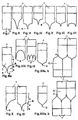
- FIGS. 1 and XIIIb show a handle 1 and an adjoining one adhesive area 2, which in turn according to Figures II to XIIIb in three areas 4, 5, 6 is divided, a first adhesive area 4, a second adhesive Area 5 and a third adhesive area 6 with tip (s) 7 at the end 3.
- the third adhesive area 6 ends in one or more tips 7.
- the first adhesive area 4 merges into the second adhesive area 5 and is labeled 8 at its end.
- Adhesive film strips suitable according to the invention can have a single-layer product structure according to DE 33 31 016 C2 and DE 42 22 849. According to the invention Adhesive film strips consisting of several can also be used Adhesive layers e.g. B. according to DE 197 08 366 including such where one or more of the adhesive layers are foamed. Furthermore are Adhesive film strips according to DE 196 49 727, DE 196 49 728, DE 196 49 729 and WO 95/06691, which have foam-containing intermediate carriers, according to the invention applicable. Adhesive films can also be used according to the invention US 4,024,312.
- Preferred adhesive tape shapes then have an optionally available non-tacky grip area ((1) in FIG. IIIa), a first area of high cross-sectional area of the pressure-sensitive adhesive tape areas, which is preferably realized by a large adhesive tape width ((2) in FIG. IIIa).
- the first adhesive strip area can at the same time have a higher average overall thickness in comparison to the second tapering adhesive strip area.
- the first adhesive strip area can taper slightly in width and / or thickness parallel to the direction of detachment (see, for example, FIG. XI).
- Preferred adhesive tape widths in the first adhesive tape area are between approximately 8 mm and approximately 30 mm, particularly preferably between approximately 10 mm and approximately 25 mm.
- Adhesive tape thicknesses are on average 400 ⁇ m to 2000 ⁇ m, preferably 500 ⁇ m to 1250 ⁇ m.
- Preferred stripping forces in the first adhesive strip area are on average greater than approx. 5 N, preferably greater than 10 N (stripping force measured for white typewriter paper ⁇ basis weight: 80 g / m 2 ⁇ stuck to coated rough fiber wallpaper; see also chapter Test methods).
- the first adhesive strip area of high cross-sectional area preferably realized by a high adhesive strip width, is followed by a second adhesive strip area, in which the cross-sectional area of the adhesive strips decreases sharply within a short distance ((3) in Fig. IIIa).
- the reduction in the cross-sectional area of the adhesive strips is achieved in particular by reducing the width of the adhesive strips. It is preferred to reduce the adhesive tape width by more than 60%, particularly preferably by more than 75% within an adhesive tape length of less than approximately 50% of the adhesive tape width at the end of the first adhesive tape area, preferably by less than 35% of the adhesive tape width at the end of the first adhesive tape area , realized.
- the tapered adhesive tape edges can be both of linear shape (see, for example, FIGS. V, VI, VII) and of non-linear, e.g. B. be curved, shape (see, for example, Fig. II to IV and VIII to XI).
- Adhesive tape ends are tapered ((4) in Fig. IIIa).
- One (see, for example, FIGS. II to IV and XI) or several (see for example FIGS. VIII and IX) pointed adhesive tape ends are possible.
- Radii of curvature of the ends of the adhesive strips are less than 0.5 mm, preferably less than 0.3 mm.
- Angles between the tapered adhesive tape edges in the adhesive tape tips are less than 35 °, preferably less than 20 °, particularly preferably less than 15 °.
- the total length of the adhesive strip is greater than approximately 20 mm, preferred lengths are approximately 25 mm to 100 mm, particularly preferably 30 mm to 65 mm.
- Adhesive strips according to the invention can optionally be used in accordance with DE 44 28 587 partial inertization of the PSA areas on both sides must be modified (see figure in Bspl. IV-02). Advantages of corresponding embodiments are the possibility of Control of the strip forces over the length of the adhesive strip, the possibility of use higher radii of curvature at the end of the adhesive strip and an additional reduction of catapult tendency and catapult powers. Partial inerting is preferred, which on identical adhesive strip surfaces in identical Way, is therefore congruent.
- Self-adhesive tapes according to the invention preferably contain, at the end of the adhesive strip, from which the detachment process is started, a non-sticky one Handle area (Fig. III, 1).
- the non-sticky grip area can, analog DE 42 22 849 or DE 43 39 604 or DE 196 49 636 thinner by lamination Plastic foils, thin papers or by printing possible.
- Last mentioned Possibility can be used particularly advantageously if at the same time the PSA area due to partial inertization in parts of the surface shall be. If a tear-resistant, foam-containing intermediate carrier z. B. accordingly WO 95/06691 used, so the non-sticky grip area due to the intermediate carrier not coated with PSA in this area be formed.
- Adhesive strips can be obtained by punching from roll goods. Is preferred a punching process according to DE 196 41 094 is used, which is largely loss-free production of die cuts allowed. There is a possibility that individual adhesive strips as well as groups of adhesive strips, e.g. B. couples, accordingly DE 196 41 094 can be punched largely without loss (see e.g. XII and XIII).
- Adhesive film strips of the desired shape and size are glued to a firmly fixed, horizontally arranged adhesive base (e.g. steel, chipboard coated with varnished woodchip wallpaper, tile, formica, etc.).
- a firmly fixed, horizontally arranged adhesive base e.g. steel, chipboard coated with varnished woodchip wallpaper, tile, formica, etc.
- the adhesive film samples are pressed onto the corresponding surface by rolling over twice using a steel roller weighing 2 kg.
- a clip is attached to the opposite narrow end of the paper strip.
- the paper strip is then pressed on by means of a 2 kg steel roller by rolling it over twice.
- the catapulting force when removing the corresponding adhesive film strip is determined by moving the adhesive tape at the selected speed (e.g. 2.5 m / min, 5 m / min, 10 m / min, 20 m / min) at an angle of maximum 3 ° to the The substrate is pulled out of the adhesive joint. If there is a noticeable sequential peeling of the adhesive film strip at the end of the peeling process results a sudden catapulting of the paper strip in the direction of detachment. The one there The force occurring is determined using the spring balance.
- Adhesive film strips of the desired shape and size are glued to a firmly fixed, vertically arranged adhesive base (e.g. steel, chipboard coated with varnished woodchip wallpaper, tile, formica, etc.) using thumb pressure.
- a firmly fixed, vertically arranged adhesive base e.g. steel, chipboard coated with varnished woodchip wallpaper, tile, formica, etc.
- paper white typewriter paper; basis weight: 80 g / m 2 ; size: DIN A4
- a touchable section of the adhesive film strip of at least 10 mm in length is centered over a narrow side of the A4 Paper protrudes vertically upwards from the glue line.
- the adhesive film strip is now pulled vertically upwards (in the direction of the handle) by pulling and stretching at a maximum angle of 3 ° to the bonding surface at a defined removal speed (e.g. 2.5 m / min, 5 m / min, 10 m / min, 20 m / min). If at the end of the detachment process the composite of adhesive film strips and the glued paper is catapulted, it is determined to what height the composite is accelerated.
- a low catapulting tendency is between approx. 10 mm and 50 mm, a noticeable catapulting tendency is those of> approx. 50 mm. If the tendency to catapult is classified as strong, there is a high risk that when using thin poster paper (thicknesses ⁇ approx. 60 ⁇ m), the poster will tear in the end area of the adhesive at the end of the detachment process. If the catapulting tendency is classified as "noticeable”, slight fiber tears are observed in some cases when using appropriately thin poster papers (thicknesses ⁇ approx. 60 ⁇ m).
- An adhesive film strip of the desired shape and size, covered on both sides with release paper, is freed from the release paper on one side and then for 10 seconds with a pressure of 10 N / cm 2 on rough-grain wallpaper coated with white dispersion paint (wallpaper: Erfurt grain size 52; color: Herbol Zenit LG; wallpaper fixed on chipboard).
- wallpaper Erfurt grain size 52; color: Herbol Zenit LG; wallpaper fixed on chipboard.
- the pressure on the adhesive strips is conveyed using a 10 mm thick foam intermediate layer (PU foam with a density of 100 kg / m 3 ).
- the second release paper is first removed from the adhesive strip, then covered with white typewriter paper with a basis weight of 80 g / m 2 (dimensions: 30 mm x 80 mm (width x length) in such a way that the adhesive strip with its handle touches the narrow side of the
- the paper strip is then pressed on by means of a 2 kg steel roller by rolling it over twice. We measure the strip force at a separation speed of 1800 mm / min.
- Rectangular adhesive strips of different widths and thicknesses are made from pieces of adhesive film of recipes 1 and 2 (PSA-1 and PSA-2), which have one end with 14 mm long, the entire width of the adhesive strips on one end to form a non-sticky grip area overcoating, polyester films (Hostaphan RN 23) are provided.
- the tendency to catapult when the adhesive strips are removed with one hand is determined (Resopal adhesive base in each case).
- Adhesive film pieces of formulation 2 are used to produce shaped adhesive strips in accordance with DE 44 28 587 (II.05-PSA-2 with a non-tacky grip area, otherwise without).
- the catapulting force as well as the tendency to catapult when the adhesive strips are removed with one hand are determined (adhesive base in each case Resopal). The following properties result:
- Stripable adhesive strips (recipe 2 (PSA-2) are produced, which have a first pressure-sensitive area that enables high peel strength and high release forces (strip forces), followed by a second pressure-sensitive area with significantly lower strip forces.
- the catapult power and tendency to catapult are determined when the adhesive strips are removed with one hand (adhesive base in each case Resopal).
- a rectangular adhesive strip and a tapered adhesive strip with a triangular basic shape are tested. The following properties result:
- Adhesive strips from tests III.03 and III.04 are initially implemented in practice the high initial stripping force comparatively carefully and slowly from the glue joint detached. As a result of those occurring in the area of adhesive tape rejuvenation strongly decreasing stripping forces (strip forces) takes place in the second (tapering) Adhesive tape area a strong acceleration of the peeling speed (Strip speed). A low strip speed in the end area of the Bonding is therefore carried out in practice with appropriately designed adhesive strips unrealized.
- adhesive strips III.03 and III.04 assign in comparison the rectangular and the triangular comparison pattern extremely low Catapult forces and a very low or undetectable tendency to catapult on.
- Double-sided pressure-sensitive adhesive strips (recipe 2 (PSA-2)) with the dimensions 50 mm x 15 mm of rectangular shape are blanket-coated on both sides in an identical manner (congruent) in parts of the end area of the adhesive strips.
- the inerting takes place in such a way that the pressure-sensitive areas taper strongly towards the end of the adhesive strip.
- Tapered PSA areas have angles of approximately 10 ° to the end of the adhesive strips.
- the test is carried out in comparison to the analog adhesive strips that are not subjected to inerting. The following properties result:
- stripable adhesive strips can be realized, which are largely independent a very low tendency to catapult from the geometric adhesive tape shape exhibit. This enables the geometry of the Adhesive tape shape from the tendency of the adhesive tape to catapult.
- Adhesive strips corresponding to example III, experiment III.03-PSA-2, experiment III.04-PSA-2 and further selected adhesive strip shapes according to the invention with a single-layer product structure are included in terms of catapulting force and tendency to catapult in comparison to multi-layer product structures (length of the 20 mm wide adhesive strips, inclusive of the non-sticky grip areas 50 mm). Radii of curvature of the ends of the adhesive tape (adhesive tape tips) were determined to be ⁇ 0.3 mm. The following properties result:
- Sample V.04-PSA-3/1/3 consists of a three-layer laminate consisting of a 600 ⁇ m thick inner layer of formulation 1, which is provided on both sides with approx. 50 ⁇ m thick outer layers of formulation 3.
- Sample V.05-PSA-1 / S / 1 consists of a 500 ⁇ m thick polyolefin foam with a density of 125 kg / m 3 (Alveolit TEE 0800.55), which is coated on both sides with approx. 200 ⁇ m thick PSA of formulation 1.
- Sample V.06-PSA-1 / F / 1 consists of a three-layer laminate containing a foamed pressure-sensitive adhesive layer with an average density of 350 kg / m 3 of formulation 1, which is coated on both sides with approximately 225 ⁇ m thick adhesive layers of the same formulation.
- the structure of sample V.07-PSA-1 / S / 1 corresponds to sample V.05-PSA-1 / S / 1, but contains a 10 mm long foam-free end area at the end. All multi-layer adhesive strips have an undetectable or undetectable to low tendency to catapult.
Landscapes
- Chemical & Material Sciences (AREA)
- Organic Chemistry (AREA)
- Adhesive Tapes (AREA)
- Adhesives Or Adhesive Processes (AREA)
- Materials For Medical Uses (AREA)
- Laminated Bodies (AREA)
Applications Claiming Priority (2)
| Application Number | Priority Date | Filing Date | Title |
|---|---|---|---|
| DE19938693A DE19938693A1 (de) | 1999-08-14 | 1999-08-14 | Klebfolienstreifen und seine Verwendung |
| DE19938693 | 1999-08-14 |
Publications (3)
| Publication Number | Publication Date |
|---|---|
| EP1077242A2 true EP1077242A2 (fr) | 2001-02-21 |
| EP1077242A3 EP1077242A3 (fr) | 2001-04-11 |
| EP1077242B1 EP1077242B1 (fr) | 2004-03-31 |
Family
ID=7918484
Family Applications (1)
| Application Number | Title | Priority Date | Filing Date |
|---|---|---|---|
| EP00116200A Expired - Lifetime EP1077242B1 (fr) | 1999-08-14 | 2000-08-03 | Ruban adhésif et son utilisation |
Country Status (5)
| Country | Link |
|---|---|
| US (1) | US6680096B1 (fr) |
| EP (1) | EP1077242B1 (fr) |
| JP (1) | JP2001089726A (fr) |
| DE (2) | DE19938693A1 (fr) |
| ES (1) | ES2216781T3 (fr) |
Cited By (3)
| Publication number | Priority date | Publication date | Assignee | Title |
|---|---|---|---|---|
| WO2005026280A1 (fr) * | 2003-09-05 | 2005-03-24 | 3M Innovative Properties Company | Bande adhesive decollable |
| EP2977419A1 (fr) * | 2014-07-23 | 2016-01-27 | Nitto Denko Corporation | Feuille adhésive étirable sensible à la pression |
| EP3428241A1 (fr) * | 2017-07-14 | 2019-01-16 | Guangdong OPPO Mobile Telecommunications Corp., Ltd. | Adhésif à décollement par étirement, ensemble de batterie et ensemble de boîtier |
Families Citing this family (38)
| Publication number | Priority date | Publication date | Assignee | Title |
|---|---|---|---|---|
| DE10129608A1 (de) | 2001-06-20 | 2003-05-28 | Tesa Ag | Stripfähige Systeme auf Basis von Acrylatblockcopolymeren |
| DE10212049A1 (de) | 2002-03-19 | 2003-10-02 | Tesa Ag | Haftklebemasse und Verfahren zur Herstellung hierzu |
| DE10252089A1 (de) | 2002-11-08 | 2004-05-27 | Tesa Ag | Klebemasse und Verwendung derselben für einen Haftklebfolienstreifen aus mindestens einer Schicht, der sich durch dehnendes Verstrecken im wesentlichen in der Verklebungsebene rückstands- und zerstörungsfrei wieder ablösen lässt |
| DE10317788A1 (de) | 2003-04-16 | 2004-12-02 | Tesa Ag | Wiederverwendbare, rückstands- und beschädigungsfrei wiederablösbare, elastische Klebefolie |
| DE10332435A1 (de) * | 2003-07-16 | 2005-02-10 | Tesa Ag | Verfahren zum Stanzen von einer zumindest einseitig klebend ausgerüsteten Bahn, die sich auf einem Abdeckmaterial befindet, in einzelne Stanzlinge |
| DE10361540A1 (de) * | 2003-12-23 | 2005-07-28 | Tesa Ag | Chemisch vernetzbare, durch Zug in Richtung der Verklebungsebene lösbare Klebestreifen |
| US7090908B1 (en) * | 2004-02-18 | 2006-08-15 | The Hartz Mountain Corporation | Lint tape roll with peeling feature |
| US7506450B2 (en) * | 2006-06-30 | 2009-03-24 | The Stanley Works | Adhesive mount for a leveling device and a leveling device |
| DE102008021740A1 (de) | 2008-04-30 | 2009-11-05 | Tesa Se | Klebemasse aus Ethylenpolymer und Verwendung derselben für einen Haftklebfolienstreifen der sich durch dehnendes Verstrecken im Wesentlichen in der Verklebungsebene rückstands- und zerstörungsfrei wieder ablösen lässt |
| DE102008033322A1 (de) * | 2008-07-16 | 2010-01-21 | Tesa Se | Verfahren und Verwendung von Klebestreifen zur Abdeckung oder Versiegelung optisch hochwertiger Oberflächen |
| JP2011241297A (ja) * | 2010-05-18 | 2011-12-01 | Kazumasa Yamamoto | 粘着シート |
| US8721095B2 (en) * | 2011-12-16 | 2014-05-13 | Targus Group International, Inc. | Attachable under-bezel tabs for display covers |
| DE202013012788U1 (de) | 2012-12-19 | 2019-08-29 | Tesa Se | Wiederablösbarer Haftklebestreifen |
| DE102012223670A1 (de) | 2012-12-19 | 2014-06-26 | Tesa Se | Wiederablösbarer Haftklebestreifen |
| US9333706B2 (en) * | 2013-09-04 | 2016-05-10 | Apple Inc. | Pull tab design for stretch release adhesive |
| DE102014208263A1 (de) | 2014-04-30 | 2015-11-05 | Tesa Se | Ablösehilfe für eine wiederablösbare Klebefolie |
| DE102014208264A1 (de) | 2014-04-30 | 2015-11-05 | Tesa Se | Hilfsklebeband für eine wiederablösbare Klebefolie |
| EP3075772B1 (fr) | 2015-04-02 | 2020-08-26 | tesa SE | Bande adhésive amovible |
| DE102015206076A1 (de) | 2015-04-02 | 2016-10-06 | Tesa Se | Wiederablösbarer Haftklebestreifen |
| DE202015009730U1 (de) | 2015-04-02 | 2019-09-06 | Tesa Se | Wiederablösbarer Haftklebestreifen |
| DE202015009724U1 (de) | 2015-04-02 | 2019-08-16 | Tesa Se | Wiederablösbarer Haftklebestreifen |
| DE202015009721U1 (de) | 2015-04-02 | 2019-08-23 | Tesa Se | Wiederablösbarer Haftklebestreifen |
| JP6633339B2 (ja) * | 2015-10-14 | 2020-01-22 | 日東電工株式会社 | タブ付き粘着製品 |
| DE102016223852A1 (de) | 2016-11-30 | 2018-05-30 | Tesa Se | Wiederablösbarer Haftklebestreifen |
| JP6778119B2 (ja) * | 2017-01-16 | 2020-10-28 | 株式会社コロナ | 住宅設備機器のリモコン |
| DE102017203092A1 (de) | 2017-02-24 | 2018-08-30 | Tesa Se | Wiederablösbarer Haftklebestreifen |
| DE102017206083A1 (de) | 2017-04-10 | 2018-10-11 | Tesa Se | Verklebung in elektrochemischen Zellen und Stapeln von elektrochemischen Zellen |
| DE102017220998A1 (de) | 2017-11-23 | 2019-05-23 | Tesa Se | Wiederablösbarer Haftklebestreifen |
| EP3724289A1 (fr) | 2017-12-11 | 2020-10-21 | 3M Innovative Properties Company | Adhésifs résistants aux chocs à décollement par étirage |
| DE102018214237A1 (de) | 2018-05-28 | 2019-11-28 | Tesa Se | Wiederablösbarer Haftklebestreifen |
| JP6912020B2 (ja) | 2019-03-04 | 2021-07-28 | Dic株式会社 | 粘着テープおよび接着体 |
| JP6933305B2 (ja) | 2019-03-04 | 2021-09-08 | Dic株式会社 | 積層フィルム、粘着テープおよび接着体 |
| WO2020195884A1 (fr) | 2019-03-26 | 2020-10-01 | Dic株式会社 | Corps lié, procédé d'assemblage de corps lié et procédé de désassemblage de corps lié |
| DE102019204344A1 (de) | 2019-03-28 | 2020-10-01 | Tesa Se | Wiederablösbarer Haftklebestreifen |
| WO2021039878A1 (fr) | 2019-08-30 | 2021-03-04 | Dic株式会社 | Ruban adhésif |
| JP7140289B2 (ja) | 2019-08-30 | 2022-09-21 | Dic株式会社 | 粘着テ-プ |
| ES2828148A1 (es) * | 2019-11-25 | 2021-05-25 | Llabres Solivellas Jose | Sistema para la unión invisible de placas frontales para rótulos |
| US11659947B2 (en) * | 2020-10-15 | 2023-05-30 | Bertha Stephanie Martinez | Shoe holder organizer |
Family Cites Families (2)
| Publication number | Priority date | Publication date | Assignee | Title |
|---|---|---|---|---|
| DE4428587C2 (de) * | 1994-08-12 | 1996-06-13 | Beiersdorf Ag | Klebfolienstreifen |
| DE19842865A1 (de) * | 1998-09-19 | 2000-03-30 | Beiersdorf Ag | Klebfolienstreifen |
-
1999
- 1999-08-14 DE DE19938693A patent/DE19938693A1/de not_active Ceased
-
2000
- 2000-08-03 ES ES00116200T patent/ES2216781T3/es not_active Expired - Lifetime
- 2000-08-03 DE DE50005863T patent/DE50005863D1/de not_active Expired - Lifetime
- 2000-08-03 EP EP00116200A patent/EP1077242B1/fr not_active Expired - Lifetime
- 2000-08-07 JP JP2000238374A patent/JP2001089726A/ja active Pending
- 2000-08-11 US US09/637,074 patent/US6680096B1/en not_active Expired - Lifetime
Cited By (4)
| Publication number | Priority date | Publication date | Assignee | Title |
|---|---|---|---|---|
| WO2005026280A1 (fr) * | 2003-09-05 | 2005-03-24 | 3M Innovative Properties Company | Bande adhesive decollable |
| EP2977419A1 (fr) * | 2014-07-23 | 2016-01-27 | Nitto Denko Corporation | Feuille adhésive étirable sensible à la pression |
| US9624404B2 (en) | 2014-07-23 | 2017-04-18 | Nitto Denko Corporation | Stretchable pressure-sensitive adhesive sheet |
| EP3428241A1 (fr) * | 2017-07-14 | 2019-01-16 | Guangdong OPPO Mobile Telecommunications Corp., Ltd. | Adhésif à décollement par étirement, ensemble de batterie et ensemble de boîtier |
Also Published As
| Publication number | Publication date |
|---|---|
| EP1077242A3 (fr) | 2001-04-11 |
| JP2001089726A (ja) | 2001-04-03 |
| EP1077242B1 (fr) | 2004-03-31 |
| DE50005863D1 (de) | 2004-05-06 |
| US6680096B1 (en) | 2004-01-20 |
| ES2216781T3 (es) | 2004-11-01 |
| DE19938693A1 (de) | 2001-02-22 |
Similar Documents
| Publication | Publication Date | Title |
|---|---|---|
| EP1077242A2 (fr) | Ruban adhésif et son utilisation | |
| DE4428587C2 (de) | Klebfolienstreifen | |
| EP0987309B1 (fr) | Ruban adhésif | |
| EP0987308A2 (fr) | Ruban adhésif | |
| DE4431914A1 (de) | Klebfolien-Streifen | |
| DE4339604C2 (de) | Verwendung eines Klebfolien-Abschnitts für eine wiederablösbare Verklebung | |
| EP0845517B1 (fr) | Utilisation d'un morceau de ruban adhésif | |
| EP2935498B1 (fr) | Bande adhésive repositionnable | |
| DE19511288C2 (de) | Verwendung eines doppelseitig klebenden Klebfolien-Abschnittes für eine Fixierung oder Aufhängung eines Gegenstandes | |
| DE2902269C2 (fr) | ||
| DE602005004934T2 (de) | Durch strecken wieder ablösbarer klebender gegenstand für zerbrechliche oberflächen | |
| EP0832587A2 (fr) | Dispositif adhésif amovible | |
| EP0590391A1 (fr) | Crochet autocollant, décollable | |
| EP0832588B1 (fr) | Dispositif adhésif amovible | |
| DE3537433A1 (de) | Wiederabloesbares klebblatt | |
| EP0878526A2 (fr) | Ruban adhesif double face et son utilisation | |
| EP0838182A2 (fr) | Crochet adhésive amovible | |
| DE19537323C2 (de) | Wiederlösbare, selbstklebende Befestigungs-Vorrichtung | |
| EP0832586A2 (fr) | Dispositif adhésif amovible avec moyen de préhension | |
| EP0997512B1 (fr) | Ruban adhésif | |
| DE19729706A1 (de) | Wiederlösbare, selbstklebende Vorrichtung | |
| DE69629622T2 (de) | Klebeband | |
| EP0965624A2 (fr) | Bande de masquage détachable et son utilisation | |
| EP3337865A1 (fr) | Procédé pour coller un corps de support | |
| DE19548475C2 (de) | Verfahren zur Bestimmung einer relativen 180 DEG Abschälfestigkeit |
Legal Events
| Date | Code | Title | Description |
|---|---|---|---|
| PUAI | Public reference made under article 153(3) epc to a published international application that has entered the european phase |
Free format text: ORIGINAL CODE: 0009012 |
|
| AK | Designated contracting states |
Kind code of ref document: A2 Designated state(s): DE ES FR GB IT |
|
| AX | Request for extension of the european patent |
Free format text: AL;LT;LV;MK;RO;SI |
|
| PUAL | Search report despatched |
Free format text: ORIGINAL CODE: 0009013 |
|
| AK | Designated contracting states |
Kind code of ref document: A3 Designated state(s): AT BE CH CY DE DK ES FI FR GB GR IE IT LI LU MC NL PT SE |
|
| AX | Request for extension of the european patent |
Free format text: AL;LT;LV;MK;RO;SI |
|
| 17P | Request for examination filed |
Effective date: 20010427 |
|
| RAP1 | Party data changed (applicant data changed or rights of an application transferred) |
Owner name: TESA AG |
|
| AKX | Designation fees paid |
Free format text: DE ES FR GB IT |
|
| 17Q | First examination report despatched |
Effective date: 20030127 |
|
| GRAP | Despatch of communication of intention to grant a patent |
Free format text: ORIGINAL CODE: EPIDOSNIGR1 |
|
| RIN1 | Information on inventor provided before grant (corrected) |
Inventor name: LUEHMANN, BERND, DR. Inventor name: JUNGHANS, ANDREAS Inventor name: FRANK, ACHIM |
|
| GRAS | Grant fee paid |
Free format text: ORIGINAL CODE: EPIDOSNIGR3 |
|
| GRAA | (expected) grant |
Free format text: ORIGINAL CODE: 0009210 |
|
| AK | Designated contracting states |
Kind code of ref document: B1 Designated state(s): DE ES FR GB IT |
|
| REG | Reference to a national code |
Ref country code: GB Ref legal event code: FG4D Free format text: NOT ENGLISH |
|
| REF | Corresponds to: |
Ref document number: 50005863 Country of ref document: DE Date of ref document: 20040506 Kind code of ref document: P |
|
| GBT | Gb: translation of ep patent filed (gb section 77(6)(a)/1977) |
Effective date: 20040607 |
|
| RAP2 | Party data changed (patent owner data changed or rights of a patent transferred) |
Owner name: TESA AG |
|
| REG | Reference to a national code |
Ref country code: ES Ref legal event code: FG2A Ref document number: 2216781 Country of ref document: ES Kind code of ref document: T3 |
|
| ET | Fr: translation filed | ||
| PLBE | No opposition filed within time limit |
Free format text: ORIGINAL CODE: 0009261 |
|
| STAA | Information on the status of an ep patent application or granted ep patent |
Free format text: STATUS: NO OPPOSITION FILED WITHIN TIME LIMIT |
|
| 26N | No opposition filed |
Effective date: 20050104 |
|
| PGFP | Annual fee paid to national office [announced via postgrant information from national office to epo] |
Ref country code: ES Payment date: 20090821 Year of fee payment: 10 |
|
| PGFP | Annual fee paid to national office [announced via postgrant information from national office to epo] |
Ref country code: GB Payment date: 20090827 Year of fee payment: 10 |
|
| REG | Reference to a national code |
Ref country code: FR Ref legal event code: CD Ref country code: FR Ref legal event code: CJ |
|
| PGFP | Annual fee paid to national office [announced via postgrant information from national office to epo] |
Ref country code: IT Payment date: 20090820 Year of fee payment: 10 |
|
| GBPC | Gb: european patent ceased through non-payment of renewal fee |
Effective date: 20100803 |
|
| PG25 | Lapsed in a contracting state [announced via postgrant information from national office to epo] |
Ref country code: IT Free format text: LAPSE BECAUSE OF NON-PAYMENT OF DUE FEES Effective date: 20100803 |
|
| PG25 | Lapsed in a contracting state [announced via postgrant information from national office to epo] |
Ref country code: GB Free format text: LAPSE BECAUSE OF NON-PAYMENT OF DUE FEES Effective date: 20100803 |
|
| REG | Reference to a national code |
Ref country code: ES Ref legal event code: FD2A Effective date: 20111019 |
|
| PG25 | Lapsed in a contracting state [announced via postgrant information from national office to epo] |
Ref country code: ES Free format text: LAPSE BECAUSE OF NON-PAYMENT OF DUE FEES Effective date: 20100804 |
|
| REG | Reference to a national code |
Ref country code: DE Ref legal event code: R081 Ref document number: 50005863 Country of ref document: DE Owner name: TESA SE, DE Free format text: FORMER OWNER: TESA SE, 20253 HAMBURG, DE |
|
| REG | Reference to a national code |
Ref country code: FR Ref legal event code: PLFP Year of fee payment: 17 |
|
| REG | Reference to a national code |
Ref country code: FR Ref legal event code: CA Effective date: 20170201 |
|
| REG | Reference to a national code |
Ref country code: FR Ref legal event code: PLFP Year of fee payment: 18 |
|
| REG | Reference to a national code |
Ref country code: FR Ref legal event code: PLFP Year of fee payment: 19 |
|
| PGFP | Annual fee paid to national office [announced via postgrant information from national office to epo] |
Ref country code: FR Payment date: 20190822 Year of fee payment: 20 Ref country code: DE Payment date: 20190822 Year of fee payment: 20 |
|
| REG | Reference to a national code |
Ref country code: DE Ref legal event code: R071 Ref document number: 50005863 Country of ref document: DE |