EP1077289A2 - Dispositif pour travailler le sol - Google Patents
Dispositif pour travailler le sol Download PDFInfo
- Publication number
- EP1077289A2 EP1077289A2 EP00307080A EP00307080A EP1077289A2 EP 1077289 A2 EP1077289 A2 EP 1077289A2 EP 00307080 A EP00307080 A EP 00307080A EP 00307080 A EP00307080 A EP 00307080A EP 1077289 A2 EP1077289 A2 EP 1077289A2
- Authority
- EP
- European Patent Office
- Prior art keywords
- tooth
- frame
- ground
- scoops
- retractable
- Prior art date
- Legal status (The legal status is an assumption and is not a legal conclusion. Google has not performed a legal analysis and makes no representation as to the accuracy of the status listed.)
- Withdrawn
Links
Images





Classifications
-
- E—FIXED CONSTRUCTIONS
- E01—CONSTRUCTION OF ROADS, RAILWAYS, OR BRIDGES
- E01C—CONSTRUCTION OF, OR SURFACES FOR, ROADS, SPORTS GROUNDS, OR THE LIKE; MACHINES OR AUXILIARY TOOLS FOR CONSTRUCTION OR REPAIR
- E01C23/00—Auxiliary devices or arrangements for constructing, repairing, reconditioning, or taking-up road or like surfaces
- E01C23/06—Devices or arrangements for working the finished surface; Devices for repairing or reconditioning the surface of damaged paving; Recycling in place or on the road
- E01C23/08—Devices or arrangements for working the finished surface; Devices for repairing or reconditioning the surface of damaged paving; Recycling in place or on the road for roughening or patterning; for removing the surface down to a predetermined depth high spots or material bonded to the surface, e.g. markings; for maintaining earth roads, clay courts or like surfaces by means of surface working tools, e.g. scarifiers, levelling blades
- E01C23/082—Devices or arrangements for working the finished surface; Devices for repairing or reconditioning the surface of damaged paving; Recycling in place or on the road for roughening or patterning; for removing the surface down to a predetermined depth high spots or material bonded to the surface, e.g. markings; for maintaining earth roads, clay courts or like surfaces by means of surface working tools, e.g. scarifiers, levelling blades using non-powered tools
-
- E—FIXED CONSTRUCTIONS
- E01—CONSTRUCTION OF ROADS, RAILWAYS, OR BRIDGES
- E01C—CONSTRUCTION OF, OR SURFACES FOR, ROADS, SPORTS GROUNDS, OR THE LIKE; MACHINES OR AUXILIARY TOOLS FOR CONSTRUCTION OR REPAIR
- E01C21/00—Apparatus or processes for surface soil stabilisation for road building or like purposes, e.g. mixing local aggregate with binder
-
- E—FIXED CONSTRUCTIONS
- E01—CONSTRUCTION OF ROADS, RAILWAYS, OR BRIDGES
- E01C—CONSTRUCTION OF, OR SURFACES FOR, ROADS, SPORTS GROUNDS, OR THE LIKE; MACHINES OR AUXILIARY TOOLS FOR CONSTRUCTION OR REPAIR
- E01C23/00—Auxiliary devices or arrangements for constructing, repairing, reconditioning, or taking-up road or like surfaces
- E01C23/06—Devices or arrangements for working the finished surface; Devices for repairing or reconditioning the surface of damaged paving; Recycling in place or on the road
- E01C23/08—Devices or arrangements for working the finished surface; Devices for repairing or reconditioning the surface of damaged paving; Recycling in place or on the road for roughening or patterning; for removing the surface down to a predetermined depth high spots or material bonded to the surface, e.g. markings; for maintaining earth roads, clay courts or like surfaces by means of surface working tools, e.g. scarifiers, levelling blades
- E01C23/085—Devices or arrangements for working the finished surface; Devices for repairing or reconditioning the surface of damaged paving; Recycling in place or on the road for roughening or patterning; for removing the surface down to a predetermined depth high spots or material bonded to the surface, e.g. markings; for maintaining earth roads, clay courts or like surfaces by means of surface working tools, e.g. scarifiers, levelling blades using power-driven tools, e.g. vibratory tools
- E01C23/088—Rotary tools, e.g. milling drums
Definitions
- This invention relates to ground working devices.
- a road resurfacing unit is disclosed in United States patent no. 5,795,096 issued August 18, 1998, which uses teeth to rip a gravel road prior to separating coarse material from fine material and depositing the coarse material on the fine material. It is desirable to have efficient separation of coarse and fine material.
- the design in US patent no. 5,795,096 uses discs commonly used in farm implements. While these work satisfactorily, there is room for improvement. The inventor has proposed a solution to the need for improved separation.
- the road resurfacing unit disclosed in United States patent no. 5,795,096 which uses teeth to rip a gravel road prior to separating coarse material from fine material and depositing the coarse material on the fine material.
- a difficulty with the design disclosed in the patent is that the teeth tend to wear. While the teeth may be individually replaced, this is time consuming.
- the inventor has proposed a solution to the wear problem of ground working equipment such as the road resurfacing unit disclosed in United States patent no. 5,795,096/.
- a ground working device comprising a sub-frame having a first side and a second side, plural discs mounted for rotation on the sub-frame between the first side and the second side about an axis that extends from the first side to the second side; and a set of scoops mounted on each disc in ground contacting position.
- the scoops efficiently lift the ground surface material, which falls to the ground in a sorted manner with coarser material on top.
- a motor is operatively connected to the plural discs for rotating the discs about the axis.
- each scoop in each set of scoops has a ground working face that extends transversely to the disc on which the respective scoop is mounted.
- the scoops each have concave ground contacting surfaces.
- Each scoop is preferably received in a respective slot in the disc in which the respective scoop is mounted.
- a main frame on which the ground working device is mounted, the main frame being provided with ground engaging wheels.
- the sub-frame is preferably retractably mounted on the main frame.
- the ground working device is preceded by a ripper bar mounted on the frame, which rips the ground surface.
- the ripper bar may be formed with retractable, replaceable teeth.
- a ground working device comprising a frame having a lower surface, and plural individually retractable teeth secured to the frame and extending away from the surface in a ground contacting array.
- Teeth for the ground working device are, in another aspect of the invention, formed as part of a retractable tooth assembly.
- a retractable tooth assembly according to a further aspect of the invention preferably comprises a tooth carrier on one end of which a tooth is slidably mounted, and on the other end of which is mounted a tooth position fixative, with a position adjustable rigid link connecting the tooth position fixative and the tooth.
- the retractable tooth assembly preferably extends through the frame from a first side to a second side, the retractable tooth assembly being secured to the frame on the first side and the tooth forming a working end on the second side.
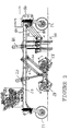
- a main frame 10 is supported by ground engaging wheels 12.
- a continuous track would also be considered ground engaging wheels for the purpose of this patent document.
- the main frame 10 carries a motor 14 and hydraulic section 16.
- a sub-frame 18 is attached under the frame 10 with hydraulic arms 20, 22 and swing arms 24 and 26.
- the hydraulic arms 20, 22 raise and lower the sub-frame 18 from the travel position shown in Fig. 1 to the maximum working position shown in Fig. 2, and may fix the sub-frame at working positions between the travel position and maximum working position.
- the swing arms 24, 26 hold the sub-frame 18 in a level position in relation to the ground, with each set of discs 28 on the sub-frame at equal height.
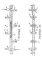
- the discs 28 (Fig. 6, 7A, 7B) have square central holes and are received on a square rod 30 that extends from one side of the sub-frame 18 to the other.
- the rod 30 defines the axis about which the discs rotate.
- Each disc 28 is formed of a central cylindrical hub 32 with plates 34 at either end and a flat disc 36 extending out from the hub 32.
- the discs 28 are slotted at equal spaced intervals around their peripheries with slightly arcuate slots 37 extending inward from the respective peripheries. Seven slots are provided, with three of the slots equally spaced and five of the slots equally spaced, one of the slots being common to both the set of three and the set of five.
- the discs 28 are held on the rod 30 with nuts 38, and interspaced along the rod 30 are bearings 40. Scoops 42 are received in the slots 37 and secured with pins 44 which extend outward from an interior portion of the discs 28.
- the scoops 42 extend transversely of the discs 28 and have slots 46 that slide over the inner surface of the discs 28 so that the scoops 42 and discs 28 dovetail onto each other.
- the scoops 42 preferably have a concave ground working surface 50, to match the curvature of the slots 37.
- the scoops 42 extend radially outward past the outer circumference of the discs 28.
- the sub-frame 18 is formed from a cental I-bar 47 with arms 45, 50, 52, 54, 56, 58 60 and 62 extending laterally from it.
- Arms 50, 52, 54, 56, 58 and 60 each terminate outwardly in a plate 64 to each which is secured, as by bolting, respective journal boxes 66.
- Bearings 40 are received in the journal housings 66.
- the discs 28 are able to rotate, along with the rod 30, about the axis defined by the rod 30.
- Arm 48 receives one end of a forward set of discs 28 and arm 62 receives one end of a rearward set of discs 28.
- Each of the arms 48 and 62 carries a motor 68, a shaft 70 of which is operatively connected to the rod 30 for rotating the rod 30.
- the motors 68 may be any of various motors, but is preferably hydraulically driven by the hydraulic section 16.
- Lobes 72, which extend upward from the sub-frame 18 are connected to the hydraulic arms 20, 22 and lobe 74 is connected to the swing arms 24, 26.
- the discs 28 are arranged on the sub-frame 18 in such a position that the scoops 42 contact the ground when the sub-frame is lowered, without the sub-frame being so low that forward progression is impeded.
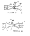
- a retractable tooth assembly 110 is formed of four main parts in the exemplary embodiment shown.
- the tooth 118 has an edge 120, which when in use is the forward edge that rips the ground.
- the edge 120 is formed of two faces 120a, 120b meeting at an apex.
- the tooth 118 also has a rearward edge 122 in which is formed a groove 124 for receiving a tongue 126 on the tooth carrier 112.
- the tooth 118 is preferably formed of a harder wearing material than the tooth carrier 112.
- the edge 120 should be made of the hardest material that is economical in the intended use, as for example tungsten carbide.
- the tooth position fixative 128 is formed of a yoke member, securely attached to the tooth carrier 112 as by a bolt 130, with a bore 132 through the member for receiving a position adjustable rigid link 134 connecting the tooth position fixative 128 and the tooth 118.
- the position adjustable rigid link 134, the fourth main part in the retractable tooth assembly 110 is preferably a constant diameter screw with exterior threads that mate with interior threads in the bore 132.
- the end 136 of the position adjustable rigid link 134 is formed as a hex nut to allow working the screw through the bore 132.
- the end 138 of the position adjustable rigid link 134 is formed as a cap rotatably received by a slot 140 in the upper end of the tooth 118.
- the tooth 118 is thus adjustably located on the tooth carrier 112 by rotating the hex nut at the end 136 of the position adjustable rigid link 134. As the tooth 118 wears, its height may be adjusted.
- the tooth 118 is the part that takes most of the wear in use of the retractable tooth assembly 110. By this design, the tooth 118 may be readily removed from the tooth carrier 112 by slipping the cap at the end 138 out of the slot 140, and sliding the tooth 118 off the tooth carrier 112.
- tooth position fixative 128 and position adjustable rigid link 134 may be used for the tooth position fixative 128 and position adjustable rigid link 134.
- the mechanism shown is a screw received by a threaded opening.
- such devices as a rack and pinion or worm and screw and other similar devices may be used to advance and retract the tooth 118 on the tooth carrier 112.
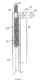
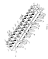
- a mount for the retractable tooth assembly 110 is shown in Fig. 14.
- the mount comprises a frame 142, which may be part of various ground working equipment such as a grader, farm implement or a road working device of the type shown in United States patent no. 5,795,096 of Culver.
- the frame 142 has a lower surface 144, which is defined as the surface closest to the ground when the frame 142 is in working position.
- Teeth 118 are secured to the frame 142 and extend away from the surface 144 in a ground contacting array.
- the teeth 118 made as shown in Figs. 11, 12 and 13, are individually retractable.
- the teeth 118 are arranged in a rectangular array as shown, with many more teeth across the width than there are rows of teeth.
- Each tooth 118 is formed as part of a retractable tooth assembly 110, which extends through the frame 142 from the upper side of the frame 142 to the lower side.
- the retractable tooth assembly 110 is secured to the frame 142 on the first side and the tooth itself forms a working end on the second side.
- the retractable tooth assembly 110 may be secured to the frame 142 using the tooth position fixative 128.
- the tooth position fixative 128 may for this purpose include a bar 146 secured to a shaft 148 extending between two posts 150 that are welded or otherwise secured to the frame 142.
- the frame 142 is formed of an upper plate 152 and lower plate 154 secured together in a casting process or by welding around their peripheries by plates 156, 158, 160 and 162.
- Mounting bars 164 are used to secure the frame 142 to swinging arms 180.
- the frame 142 is raised and lowered using hydraulic arms 182 attached to either side of the frame 10 and to the frame 142 with pins inserted into openings 184 in the frame 142.
- the height of the retractable teeth is controlled using hydraulic controls for the hydraulic arms 182.
- the frame 10 may be attached by any suitable means such as by plates 186 to a vehicle, such as a grader or tractor, that tows the apparatus across a road surface. While the invention as disclosed and claimed is a road resurfacing device, when applied to roads one of the objects of the invention is to restore, reconstruct and reshape the road as much as possible during the resurfacing process.
Landscapes
- Engineering & Computer Science (AREA)
- Architecture (AREA)
- Civil Engineering (AREA)
- Structural Engineering (AREA)
- Mining & Mineral Resources (AREA)
- Mechanical Engineering (AREA)
- Road Repair (AREA)
- Soil Working Implements (AREA)
- Shovels (AREA)
Applications Claiming Priority (4)
| Application Number | Priority Date | Filing Date | Title |
|---|---|---|---|
| CA002280297A CA2280297C (fr) | 1999-08-18 | 1999-08-18 | Dispositif retractable servant a ameublir la terre |
| CA2280297 | 1999-08-18 | ||
| CA 2293885 CA2293885C (fr) | 1999-12-30 | 1999-12-30 | Dispositif de travail du sol |
| CA2293885 | 1999-12-30 |
Publications (2)
| Publication Number | Publication Date |
|---|---|
| EP1077289A2 true EP1077289A2 (fr) | 2001-02-21 |
| EP1077289A3 EP1077289A3 (fr) | 2003-01-08 |
Family
ID=30001262
Family Applications (1)
| Application Number | Title | Priority Date | Filing Date |
|---|---|---|---|
| EP00307080A Withdrawn EP1077289A3 (fr) | 1999-08-18 | 2000-08-18 | Dispositif pour travailler le sol |
Country Status (2)
| Country | Link |
|---|---|
| EP (1) | EP1077289A3 (fr) |
| AU (1) | AU777976B2 (fr) |
Cited By (3)
| Publication number | Priority date | Publication date | Assignee | Title |
|---|---|---|---|---|
| CN104093908A (zh) * | 2011-09-30 | 2014-10-08 | 卡特彼勒路面机械公司 | 在机架与传送器之间具有枢转式连接的机器 |
| CN110258486A (zh) * | 2019-07-01 | 2019-09-20 | 台州路桥博仁环保设备有限公司 | 一种河道闸口漂浮垃圾环保清理装置 |
| CN111560967A (zh) * | 2020-06-04 | 2020-08-21 | 丽水莲都晶格智能科技有限公司 | 一种涵洞可快速排水防淹的装置 |
Citations (1)
| Publication number | Priority date | Publication date | Assignee | Title |
|---|---|---|---|---|
| US5795096A (en) | 1996-09-06 | 1998-08-18 | Lci International Inc. | Road resurfacing system |
Family Cites Families (4)
| Publication number | Priority date | Publication date | Assignee | Title |
|---|---|---|---|---|
| US1970531A (en) * | 1932-12-08 | 1934-08-14 | York Modern Corp | Road scarifier |
| GB1313744A (en) * | 1969-08-01 | 1973-04-18 | Rotary Hoes Ltd | Rotary cultivator machine |
| DE3043175A1 (de) * | 1980-11-15 | 1982-10-07 | Ernst 7326 Heiningen Weichel | Geraet zum auflockern und zerkleinern von verdichteten bodenschichten |
| JPH045548Y2 (fr) * | 1986-12-03 | 1992-02-17 |
-
2000
- 2000-08-18 EP EP00307080A patent/EP1077289A3/fr not_active Withdrawn
- 2000-08-18 AU AU53481/00A patent/AU777976B2/en not_active Ceased
Patent Citations (1)
| Publication number | Priority date | Publication date | Assignee | Title |
|---|---|---|---|---|
| US5795096A (en) | 1996-09-06 | 1998-08-18 | Lci International Inc. | Road resurfacing system |
Cited By (4)
| Publication number | Priority date | Publication date | Assignee | Title |
|---|---|---|---|---|
| CN104093908A (zh) * | 2011-09-30 | 2014-10-08 | 卡特彼勒路面机械公司 | 在机架与传送器之间具有枢转式连接的机器 |
| CN104093908B (zh) * | 2011-09-30 | 2016-06-08 | 卡特彼勒路面机械公司 | 在机架与传送器之间具有枢转式连接的机器 |
| CN110258486A (zh) * | 2019-07-01 | 2019-09-20 | 台州路桥博仁环保设备有限公司 | 一种河道闸口漂浮垃圾环保清理装置 |
| CN111560967A (zh) * | 2020-06-04 | 2020-08-21 | 丽水莲都晶格智能科技有限公司 | 一种涵洞可快速排水防淹的装置 |
Also Published As
| Publication number | Publication date |
|---|---|
| AU777976B2 (en) | 2004-11-04 |
| EP1077289A3 (fr) | 2003-01-08 |
| AU5348100A (en) | 2001-02-22 |
Similar Documents
| Publication | Publication Date | Title |
|---|---|---|
| US5002656A (en) | Rotary grid-structure bucket for separating from each other fine and coarse particles of sizable materials or products | |
| DE2458918C2 (de) | Bodenbearbeitungsmaschine | |
| US7500803B2 (en) | Ground working device for liquid treated roads | |
| US4407080A (en) | Pivotally mounted ripping teeth assembly on dozer blade | |
| US4373590A (en) | Tilling apparatus | |
| US6368014B1 (en) | Ground working device | |
| US4398607A (en) | Auger with adjustable wear plate | |
| US3964719A (en) | Mobile stone crushing plant | |
| WO1996015654A1 (fr) | Motobineuse a fraise rotative | |
| US5795096A (en) | Road resurfacing system | |
| EP0122216B1 (fr) | Dispositif d'enlèvement, en particulier de déneigement | |
| US4467874A (en) | Tine and tine and hub assembly | |
| CA2147012C (fr) | Concasseur autonome et portable | |
| US3589452A (en) | Tine-mounting assembly | |
| AU777976B2 (en) | Ground working device | |
| US6257342B1 (en) | Soil grading apparatus | |
| CA2293885C (fr) | Dispositif de travail du sol | |
| US5775012A (en) | Utility blade hitched to a vehicle | |
| US4698925A (en) | Soil reclaiming implement | |
| EP0127587B1 (fr) | Unité de désagrégation mobile pour défricher et déblayer des terrains inégaux, pour préparer des assiettes de routes et des coffrages routiers, pour travaux de mines à ciel ouvert et cetera | |
| EP1438460B1 (fr) | Broyeuse | |
| US6283224B1 (en) | Retractable ground working device | |
| JPH07107829A (ja) | 収穫機 | |
| US9844172B2 (en) | Attachment for engineering vehicle | |
| WO1992018698A1 (fr) | Disposifif pour la mise en etat des bordures de routes |
Legal Events
| Date | Code | Title | Description |
|---|---|---|---|
| PUAI | Public reference made under article 153(3) epc to a published international application that has entered the european phase |
Free format text: ORIGINAL CODE: 0009012 |
|
| AK | Designated contracting states |
Kind code of ref document: A2 Designated state(s): AT BE CH CY DE DK ES FI FR GB GR IE IT LI LU MC NL PT SE |
|
| AX | Request for extension of the european patent |
Free format text: AL;LT;LV;MK;RO;SI |
|
| RIC1 | Information provided on ipc code assigned before grant |
Free format text: 7E 01C 23/088 A, 7E 01C 23/082 B, 7E 01C 21/00 B |
|
| PUAL | Search report despatched |
Free format text: ORIGINAL CODE: 0009013 |
|
| AK | Designated contracting states |
Kind code of ref document: A3 Designated state(s): AT BE CH CY DE DK ES FI FR GB GR IE IT LI LU MC NL PT SE |
|
| AX | Request for extension of the european patent |
Free format text: AL;LT;LV;MK;RO;SI |
|
| 17P | Request for examination filed |
Effective date: 20030708 |
|
| AKX | Designation fees paid |
Designated state(s): AT BE CH CY DE DK ES FI FR GB GR IE IT LI LU MC NL PT SE |
|
| 17Q | First examination report despatched |
Effective date: 20050915 |
|
| 17Q | First examination report despatched |
Effective date: 20050915 |
|
| STAA | Information on the status of an ep patent application or granted ep patent |
Free format text: STATUS: THE APPLICATION IS DEEMED TO BE WITHDRAWN |
|
| 18D | Application deemed to be withdrawn |
Effective date: 20080502 |