EP1077308A1 - Aube ou aube de guidage de turbomachine avec un repère d' usinage capable de survivre - Google Patents
Aube ou aube de guidage de turbomachine avec un repère d' usinage capable de survivre Download PDFInfo
- Publication number
- EP1077308A1 EP1077308A1 EP00306817A EP00306817A EP1077308A1 EP 1077308 A1 EP1077308 A1 EP 1077308A1 EP 00306817 A EP00306817 A EP 00306817A EP 00306817 A EP00306817 A EP 00306817A EP 1077308 A1 EP1077308 A1 EP 1077308A1
- Authority
- EP
- European Patent Office
- Prior art keywords
- blade
- depression
- depth
- prefinished
- datum
- Prior art date
- Legal status (The legal status is an assumption and is not a legal conclusion. Google has not performed a legal analysis and makes no representation as to the accuracy of the status listed.)
- Granted
Links
- 238000004519 manufacturing process Methods 0.000 claims abstract description 27
- 238000003754 machining Methods 0.000 claims abstract description 26
- 239000012530 fluid Substances 0.000 claims description 20
- 238000007689 inspection Methods 0.000 abstract description 9
- 230000008439 repair process Effects 0.000 abstract description 4
- 241000237509 Patinopecten sp. Species 0.000 description 7
- 235000020637 scallop Nutrition 0.000 description 7
- 238000005266 casting Methods 0.000 description 5
- 238000009419 refurbishment Methods 0.000 description 4
- 238000003491 array Methods 0.000 description 3
- 238000004873 anchoring Methods 0.000 description 2
- 230000000994 depressogenic effect Effects 0.000 description 2
- 238000009434 installation Methods 0.000 description 2
- 239000000463 material Substances 0.000 description 2
- 230000002093 peripheral effect Effects 0.000 description 2
- 238000009825 accumulation Methods 0.000 description 1
- 230000006978 adaptation Effects 0.000 description 1
- 239000000956 alloy Substances 0.000 description 1
- 229910045601 alloy Inorganic materials 0.000 description 1
- 230000004888 barrier function Effects 0.000 description 1
- 230000009286 beneficial effect Effects 0.000 description 1
- 230000008901 benefit Effects 0.000 description 1
- 230000000295 complement effect Effects 0.000 description 1
- 230000001010 compromised effect Effects 0.000 description 1
- 230000007423 decrease Effects 0.000 description 1
- 230000001419 dependent effect Effects 0.000 description 1
- 230000001627 detrimental effect Effects 0.000 description 1
- 230000003467 diminishing effect Effects 0.000 description 1
- 230000002349 favourable effect Effects 0.000 description 1
- 238000000034 method Methods 0.000 description 1
- 239000000203 mixture Substances 0.000 description 1
- 238000012986 modification Methods 0.000 description 1
- 230000004048 modification Effects 0.000 description 1
- 230000009467 reduction Effects 0.000 description 1
Images

Classifications
-
- F—MECHANICAL ENGINEERING; LIGHTING; HEATING; WEAPONS; BLASTING
- F01—MACHINES OR ENGINES IN GENERAL; ENGINE PLANTS IN GENERAL; STEAM ENGINES
- F01D—NON-POSITIVE DISPLACEMENT MACHINES OR ENGINES, e.g. STEAM TURBINES
- F01D5/00—Blades; Blade-carrying members; Heating, heat-insulating, cooling or antivibration means on the blades or the members
- F01D5/12—Blades
-
- B—PERFORMING OPERATIONS; TRANSPORTING
- B23—MACHINE TOOLS; METAL-WORKING NOT OTHERWISE PROVIDED FOR
- B23C—MILLING
- B23C3/00—Milling particular work; Special milling operations; Machines therefor
- B23C3/28—Grooving workpieces
-
- F—MECHANICAL ENGINEERING; LIGHTING; HEATING; WEAPONS; BLASTING
- F01—MACHINES OR ENGINES IN GENERAL; ENGINE PLANTS IN GENERAL; STEAM ENGINES
- F01D—NON-POSITIVE DISPLACEMENT MACHINES OR ENGINES, e.g. STEAM TURBINES
- F01D5/00—Blades; Blade-carrying members; Heating, heat-insulating, cooling or antivibration means on the blades or the members
- F01D5/005—Repairing methods or devices
-
- F—MECHANICAL ENGINEERING; LIGHTING; HEATING; WEAPONS; BLASTING
- F01—MACHINES OR ENGINES IN GENERAL; ENGINE PLANTS IN GENERAL; STEAM ENGINES
- F01D—NON-POSITIVE DISPLACEMENT MACHINES OR ENGINES, e.g. STEAM TURBINES
- F01D5/00—Blades; Blade-carrying members; Heating, heat-insulating, cooling or antivibration means on the blades or the members
- F01D5/12—Blades
- F01D5/14—Form or construction
-
- F—MECHANICAL ENGINEERING; LIGHTING; HEATING; WEAPONS; BLASTING
- F05—INDEXING SCHEMES RELATING TO ENGINES OR PUMPS IN VARIOUS SUBCLASSES OF CLASSES F01-F04
- F05D—INDEXING SCHEME FOR ASPECTS RELATING TO NON-POSITIVE-DISPLACEMENT MACHINES OR ENGINES, GAS-TURBINES OR JET-PROPULSION PLANTS
- F05D2230/00—Manufacture
- F05D2230/60—Assembly methods
- F05D2230/64—Assembly methods using positioning or alignment devices for aligning or centring, e.g. pins
-
- F—MECHANICAL ENGINEERING; LIGHTING; HEATING; WEAPONS; BLASTING
- F05—INDEXING SCHEMES RELATING TO ENGINES OR PUMPS IN VARIOUS SUBCLASSES OF CLASSES F01-F04
- F05D—INDEXING SCHEME FOR ASPECTS RELATING TO NON-POSITIVE-DISPLACEMENT MACHINES OR ENGINES, GAS-TURBINES OR JET-PROPULSION PLANTS
- F05D2230/00—Manufacture
- F05D2230/80—Repairing, retrofitting or upgrading methods
Definitions
- This invention relates to turbomachinery blades and vanes and particularly to a blade or vane having a machining datum whose utility survives the original manufacturing process so that the datum is available for use in post-manufacturing inspection and repair operations.
- Gas turbine engines and similar turbomachines have one or more compressors and turbines.
- the compressors and turbines include longitudinally alternating arrays of blades and vanes that extend radially across an annular flowpath.
- a working medium fluid flows longitudinally through the flowpath.
- the blades and vanes interact with the working medium fluid to transfer energy from the compressor to the fluid and from the fluid to the turbine.
- a typical turbine blade has a root that adapts the blade to be secured to a rotatable hub so that the blade extends radially outwardly from the hub.
- the blade also includes a platform adjacent to the root, a shroud radially spaced apart from the platform and an airfoil spanning between the platform and the shroud.
- the airfoil has an intangible, spanwisely extending stacking line, which is a manufacturing reference for establishing the contour of the airfoil and the spatial relationship of the airfoil relative to the platform and shroud.
- the blade also has a knife edge that extends outwardly from the radially outer surface of the shroud.
- the blade platforms and shrouds define radially inner and outer boundaries of a flowpath for the working medium fluid, and the airfoils span radially across the flowpath.
- the knife edges of the installed blades abut each other to form a substantially circumferentially continuous knife edge ring.
- the knife edge ring extends radially toward an abradable seal that circumscribes the blade array.
- the turbine blades are made from a high strength, temperature tolerant alloy that is cast to a near net shape.
- the blade casting is then polished to smooth out any minor irregularities in the airfoil surface and to remove any excess material from the airfoil's leading and trailing edges.
- the blade platform and shroud are then finish machined to render the blade dimensionally and geometrically suitable for installation and service in the turbomachine.
- the finish machining of the platform and shroud is conducted according to a highly automated manufacturing protocol known as "one piece flow".
- This protocol features a sequence of machines arranged in a logistically optimized flow line in a manufacturing facility. Each machine performs one of several required machining steps, and operates on only one blade at a time. Each blade is transferred from machine to machine in the flow line. In order to guard against the accumulation of machining inaccuracies due to these transfers, the blade has a set of dedicated, highly accurate machining datums.
- One of the dedicated datums found on conventional blades is a projection that extends radially outwardly from the shroud.
- the projection has a radially inner portion that is recessed in a pocket in the shroud outer surface and blends into a pocket sidewall so that the radially inner portion of the projection is peripherally noncontinuous.
- the projection also has a radially outer portion that extends radially beyond the sidewall and therefore is peripherally continuous.
- the peripherally continuous outer portion serves not only as a reference point but also as one of a number of interfaces by means of which the blade can be predictably positioned and anchored in place in each of the one piece flow machines.
- the outer portion of the projection would cut into the seal that circumscribes the blade array in much the same way that the knife edge ring cuts into the seal. Because the knife edge ring and the projection are separated by only a small distance, and because the hub shifts slightly in the longitudinal direction during engine operation, the cut made by the projection can merge with and expand the width of the knife edge groove. As a result the desired snug fit between the knife edge ring and the knife edge groove is undermined thereby diminishing the effectiveness of the seal and reducing the turbomachine's efficiency. To guard against this occurrence, the outer portion of the projection is machined off, leaving behind only the inner portion, which is too short to contact the seal. The removal of the outer portion also destroys the projection's utility as a datum, and therefore the outer portion is not removed until all the other machining operations are complete and the projection is no longer necessary to facilitate blade manufacture.
- Turbine blades such as those just described, must also undergo post-manufacturing dimensional inspections.
- the above described machining projection would be an ideal inspection reference point.
- alternative reference points are two sets of datum triplets on the airfoil, one set near the platform and one near the shroud. These datum triplets are far less accurate than the machining projection, and therefore overly stringent inspection criteria must be established to ensure that all dimensionally unacceptable blades are identified. As a result, some blades that are dimensionally acceptable will be identified as unacceptable, and will be scrapped. Given the high cost of turbomachinery blades it is clearly desirable to minimize the likelihood that a serviceable blade is erroneously identified as unacceptable.
- the survivable datum disclosed in the above noted patent application is superior to a nonsurvivable datum, but is not without certain shortcomings. Although much of the projection is recessed within a pocket, the tip of the projection is exposed and therefore vulnerable to possible handling damage. Moreover, in the disclosed blade, the highly desirable alignment of the datum axis with the stacking line is obtained by introducing a scallop into the pocket sidewall. In blades that require a generous scallop, the presence of the scallop can degrade the stiffness of the shroud, making it susceptible to undesirable, centrifugally induced deflections during engine operation. Although a generous scallop could be avoided by repositioning the datum elsewhere on the shroud, such repositioning would separate the datum axis from the stacking line, thereby complicating the tooling required for blade manufacture.
- an object of the invention to provide a turbine blade or vane with a survivable machining datum so that post manufacturing inspection and refurbishment can be carried out with the degree of accuracy and confidence enjoyed during the original manufacturing process.
- a turbomachinery blade or vane generically referred to herein as fluid reaction elements, has a depression that serves as a datum and as an interface for anchoring the blade or vane during manufacturing operations.
- the depression has a prefinished depth and a smaller finished depth. Both the prefinished and finished depths are sufficient to act as a support feature during manufacturing operations.
- the datum has a substantially frustoconical profile in both the prefinished and finished states.
- the profile is defined by a cone angle favorable for both the casting and finishing phases of blade manufacture.
- a turbomachinery blade comprises a platform, a shroud, an airfoil extending therebetween, and a depressed, frustoconical machining datum residing in the shroud.
- the blade has a prefinished state in which the datum has a prefinished depth and a finished state in which the datum has a finished depth.
- the finished depth is smaller than the prefinished depth but is nevertheless capable of acting as both a reference and support feature during post manufacture inspection and refurbishment.
- the invention is advantageous in several respects.
- the utility of the depression transcends the manufacturing process so that post-manufacturing inspection and repair procedures can be carried out with the same degree of accuracy as the original manufacturing operations.
- blade scrap rates can be reduced and the full potential of refurbishment operations can be realized.
- the non-projecting character of the datum makes it inherently immune to handling damage.
- a turbomachine exemplified by gas turbine engine 10 includes one or more compressors 12 , and one or more turbines 14 disposed about a longitudinally extending central axis 16 .
- the compressors and turbines include one or more arrays of blades, such as low pressure turbine blade 18 , extending radially outwardly from a rotatable hub 20 , and one or more arrays of nonrotatable, radially extending vanes such as turbine vane 22 .
- a working medium fluid 24 flows longitudinally through an annular flowpath 26 and interacts with the blades and vanes to exchange energy with the compressors and turbines.
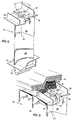
- Figures 2 , 3 and 4 show turbine blade 18 in greater detail.
- Figure 2 shows the blade in its prefinished state, i.e. prior to finish machining operations that render the blade geometrically and dimensionally suitable for installation in an engine.
- Figures 3 and 4 show the blade in its finished state.
- the blade 18 includes a root 32 , a platform 34 adjacent to the root, a shroud 36 and an airfoil 38 spanning between the root and the shroud.
- the shroud and platform of each blade cooperate with the shrouds and platforms of the other blades in the array to define the outer and inner boundaries of the flowpath.
- An intangible, spanwisely extending stacking line 40 serves as a reference for establishing the airfoil's contour as well as its spatial relationship to the platform and shroud.
- the blade shroud 36 includes a thick stiffening rail 41 . During engine operation the rail helps to resist excessive shroud curling, which is an undesirable, centrifugally induced deflection of the shroud.
- the blade shroud also includes a pair of knife edges 42 , each of which extends radially outwardly toward an abradable seal 44 (Fig. 3 ) that circumscribes the blade array. Each knife edge also extends circumferentially and abuts the knife edges of the adjacent blades in the array to form a substantially continuous, circumferentially extending knife edge ring 46 .
- the knife edge ring When the engine is initially assembled, the knife edge ring does not contact the seal. However during a brief break-in period when the engine is first operated at high power, mechanical deflections and thermally induced dimensional changes cause each knife edge ring to cut a knife edge groove 50 into the seal. Thereafter, the ring protrudes into the groove during high power operation to form a barrier against the leakage of working medium fluid past the airfoils.
- the blade also includes a depression 52 that resides in the outer face of the shroud and serves as both a machining datum and as an interface for a support tool 67 (Fig. 4 ) to anchor the blade during machining operations.
- the depression In the prefinished state (Fig. 2 ) the depression has prefinished depth d 1 and a substantially frustoconical profile defined by a cone angle ⁇ .
- the prefinished depth is deep enough and the cone angle is small enough that the depression can serve as a reliable support feature during machining operations.
- the datum is symmetric about a cone axis 56 and is positioned so that the axis 56 is substantially aligned with (i.e. collinear with) the stacking line 40 . When the blade is installed in an engine, the datum axis and stacking line are oriented radially.
- the selected magnitude of cone angle ⁇ is influenced by both machining and casting considerations. From a casting standpoint, larger cone angles are preferred because larger cone angles are easier to cast into the blade shroud, and smaller angles are harder to cast. However if the angle is too large, machining forces transverse to the cone axis can dislodge the blade from the support tool 67 . A smaller cone angle provides more reliable support. But if the cone angle is too small, proper engagement of the support tool with the depression can be compromised by imprecisions in the diameter of the depression. Ideally, the tool engagement depth e (Fig. 4 ) should be slightly less than the depth of the depression ( d 2 in Fig 4 ) limited only by the fillet radius 68 at the inner end of the depression.
- a slightly undersized diameter at a small (steep) cone angle can severely limit the tool engagement depth.
- a slightly oversized diameter can allow the tool to contact the bottom of the depression before the peripheral surface of the tool contacts the surface of the depression.
- the illustrated blade has a cone angle ⁇ of 90° for ease of casting even though a smaller, 60° cone angle is preferred from a machining standpoint.
- the blade In the fully finished state ( Figures 3 , 4 ) the blade has been machined so that it is geometrically and dimensionally suitable for service in an engine.
- the final machining operation shaves material off the stiffening rail 41 and therefore decreases the depth of the depression 52 from its prefinished depth d 1 to a finished depth d 2 .
- the geometry of the depression e.g. its cone angle, symmetry about axis 56 and alignment with stacking line 40 , is otherwise unaffected.
- the depression remains deep enough that the tool engagement distance e still exceeds a predetermined distance.
- the predetermined distance is sufficiently large to reliably anchor the blade against the forces applied during finish machining operations. Because the datum retains its utility as both a reference point and as a support feature, post manufacturing inspections and repairs can also benefit from its presence.
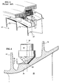
- the invention can be better appreciated in comparison with a blade 18' described in the above noted patent application and shown in its finished state in Figure 5 .
- the blade has a projecting datum 52' whose axis 56' is aligned with the airfoil stacking line 40' .
- the post-manufacture utility of the datum has been ensured, in part, by introducing a scallop 66' into stiffening rail 41' so that in the finished state the datum is both peripherally continuous and coincident with the stacking line 40' .
- the projecting character of the datum renders it somewhat susceptible to handling damage, whereas the depressed datum 52 of the inventive blade is substantially immune to damage.
- scallop 66' of the earlier generation blade can compromise the stiffness of stiffening rail 41' , especially if the scallop is generous.
- the depression 52 of the inventive blade is less detrimental to the stiffness of the rail 41 .
- the alignment of datum axis 56 with the stacking line 40 and the symmetry of the datum about axis 56 are also beneficial. Alignment of the datum axis and the stacking line is desirable because the angular orientation of the blade is not the same in each of the machines of the one piece flow line. If the datum were not aligned with the stacking line, the spatial position of the stacking line and other physical features on the blade would be orientation dependent, which would complicate the fixturing tools for each machine in the one piece flow line -- i.e. each machine's fixturing tools would have to be customized to account for the lack of alignment.
- the spatial position of the airfoil features is independent of the blade's angular orientation, thereby simplifying the tooling. Symmetry of the datum about the datum axis also simplifies the tooling which would have to be customized if the datum were asymmetrical.
Landscapes
- Engineering & Computer Science (AREA)
- Mechanical Engineering (AREA)
- General Engineering & Computer Science (AREA)
- Turbine Rotor Nozzle Sealing (AREA)
- Structures Of Non-Positive Displacement Pumps (AREA)
Applications Claiming Priority (2)
| Application Number | Priority Date | Filing Date | Title |
|---|---|---|---|
| US09/376,225 US6179567B1 (en) | 1999-08-18 | 1999-08-18 | Turbomachinery blade or vane with a survivable machining datum |
| US376225 | 1999-08-18 |
Publications (2)
| Publication Number | Publication Date |
|---|---|
| EP1077308A1 true EP1077308A1 (fr) | 2001-02-21 |
| EP1077308B1 EP1077308B1 (fr) | 2004-10-27 |
Family
ID=23484164
Family Applications (1)
| Application Number | Title | Priority Date | Filing Date |
|---|---|---|---|
| EP00306817A Expired - Lifetime EP1077308B1 (fr) | 1999-08-18 | 2000-08-10 | Aube ou aube de guidage de turbomachine avec un repère d' usinage capable de survivre |
Country Status (5)
| Country | Link |
|---|---|
| US (1) | US6179567B1 (fr) |
| EP (1) | EP1077308B1 (fr) |
| JP (1) | JP2001073703A (fr) |
| KR (1) | KR20010021293A (fr) |
| DE (1) | DE60015259T2 (fr) |
Cited By (4)
| Publication number | Priority date | Publication date | Assignee | Title |
|---|---|---|---|---|
| GB2428396A (en) * | 2005-07-21 | 2007-01-31 | Rolls Royce Plc | A method of manufacturing an article with a reference datum feature |
| WO2008155513A1 (fr) * | 2007-06-16 | 2008-12-24 | Rolls-Royce Plc | Procédé de fabrication utilisant les mêmes éléments de référence sur des pièces différentes |
| CN103639494A (zh) * | 2013-11-18 | 2014-03-19 | 四川成发航空科技股份有限公司 | 一种加工航空发动机导向叶片小锁板的方法 |
| US10099433B2 (en) | 2015-08-11 | 2018-10-16 | Rolls-Royce Plc | Datum feature for a composite component |
Families Citing this family (16)
| Publication number | Priority date | Publication date | Assignee | Title |
|---|---|---|---|---|
| US6491498B1 (en) * | 2001-10-04 | 2002-12-10 | Power Systems Mfg, Llc. | Turbine blade pocket shroud |
| US6906808B2 (en) * | 2002-05-30 | 2005-06-14 | General Electric Company | Methods and apparatus for measuring a surface contour of an object |
| US6842995B2 (en) * | 2002-10-09 | 2005-01-18 | General Electric Company | Methods and apparatus for aligning components for inspection |
| US6886422B2 (en) * | 2002-10-09 | 2005-05-03 | General Electric Co. | Methods and apparatus for inspecting components |
| US7001144B2 (en) * | 2003-02-27 | 2006-02-21 | General Electric Company | Gas turbine and method for reducing bucket tip shroud creep rate |
| CN1326652C (zh) * | 2004-12-30 | 2007-07-18 | 东方汽轮机厂 | 一种汽轮机组调节级动叶片叶冠的加工方法及装置 |
| DE102005062303A1 (de) * | 2005-12-24 | 2007-06-28 | Rolls-Royce Deutschland Ltd & Co Kg | Verfahren und Anordnung zur Fertigbearbeitung von aus einem spröden Werkstoff gegossenen Schaufeln für ein Gasturbinentriebwerk |
| US7237525B1 (en) * | 2006-08-08 | 2007-07-03 | International Engine Intellectual Property Company, Llc | Engine cast component having witness marks and method of machining same |
| US9643286B2 (en) * | 2007-04-05 | 2017-05-09 | United Technologies Corporation | Method of repairing a turbine engine component |
| US8220150B2 (en) * | 2007-05-22 | 2012-07-17 | United Technologies Corporation | Split vane cluster repair method |
| US8206121B2 (en) * | 2008-03-26 | 2012-06-26 | United Technologies Corporation | Method of restoring an airfoil blade |
| US20090274562A1 (en) * | 2008-05-02 | 2009-11-05 | United Technologies Corporation | Coated turbine-stage nozzle segments |
| FR2967714B1 (fr) * | 2010-11-22 | 2012-12-14 | Snecma | Aube mobile de turbomachine |
| US20130318996A1 (en) * | 2012-06-01 | 2013-12-05 | General Electric Company | Cooling assembly for a bucket of a turbine system and method of cooling |
| EP3736073B1 (fr) * | 2013-02-28 | 2025-12-10 | RTX Corporation | Procédé de reparation d'une piece aeronautique |
| CN106425633B (zh) * | 2016-11-29 | 2018-07-20 | 沈阳黎明航空发动机(集团)有限责任公司 | 一种满足双缘板叶片型面铣削加工快速找正要求的方法 |
Citations (4)
| Publication number | Priority date | Publication date | Assignee | Title |
|---|---|---|---|---|
| US4607460A (en) * | 1985-04-18 | 1986-08-26 | Hauni-Werke Korber & Co. Kg | Grinding machine with a reciprocable column for work supporting devices |
| US5384950A (en) * | 1994-05-12 | 1995-01-31 | Harnischfeger Corporation | Method for machining a component |
| US5544873A (en) * | 1991-12-23 | 1996-08-13 | Alliedsignal Inc. | Apparatus to hold compressor or turbine blade during manufacture |
| EP0909879A2 (fr) | 1997-10-17 | 1999-04-21 | United Technologies Corporation | Aube de turbomachine avec un repère permanent pour l'usinage |
Family Cites Families (2)
| Publication number | Priority date | Publication date | Assignee | Title |
|---|---|---|---|---|
| US4576551A (en) | 1982-06-17 | 1986-03-18 | The Garrett Corporation | Turbo machine blading |
| US5288209A (en) | 1991-12-19 | 1994-02-22 | General Electric Company | Automatic adaptive sculptured machining |
-
1999
- 1999-08-18 US US09/376,225 patent/US6179567B1/en not_active Expired - Lifetime
-
2000
- 2000-08-10 DE DE60015259T patent/DE60015259T2/de not_active Expired - Lifetime
- 2000-08-10 EP EP00306817A patent/EP1077308B1/fr not_active Expired - Lifetime
- 2000-08-14 KR KR1020000046870A patent/KR20010021293A/ko not_active Abandoned
- 2000-08-18 JP JP2000248148A patent/JP2001073703A/ja not_active Ceased
Patent Citations (4)
| Publication number | Priority date | Publication date | Assignee | Title |
|---|---|---|---|---|
| US4607460A (en) * | 1985-04-18 | 1986-08-26 | Hauni-Werke Korber & Co. Kg | Grinding machine with a reciprocable column for work supporting devices |
| US5544873A (en) * | 1991-12-23 | 1996-08-13 | Alliedsignal Inc. | Apparatus to hold compressor or turbine blade during manufacture |
| US5384950A (en) * | 1994-05-12 | 1995-01-31 | Harnischfeger Corporation | Method for machining a component |
| EP0909879A2 (fr) | 1997-10-17 | 1999-04-21 | United Technologies Corporation | Aube de turbomachine avec un repère permanent pour l'usinage |
Cited By (6)
| Publication number | Priority date | Publication date | Assignee | Title |
|---|---|---|---|---|
| GB2428396A (en) * | 2005-07-21 | 2007-01-31 | Rolls Royce Plc | A method of manufacturing an article with a reference datum feature |
| WO2008155513A1 (fr) * | 2007-06-16 | 2008-12-24 | Rolls-Royce Plc | Procédé de fabrication utilisant les mêmes éléments de référence sur des pièces différentes |
| US8516676B2 (en) | 2007-06-16 | 2013-08-27 | Rolls-Royce Plc | Method of manufacture of aerofoil assemblies having datum features located in complementary fixtures |
| CN103639494A (zh) * | 2013-11-18 | 2014-03-19 | 四川成发航空科技股份有限公司 | 一种加工航空发动机导向叶片小锁板的方法 |
| CN103639494B (zh) * | 2013-11-18 | 2016-09-14 | 四川成发航空科技股份有限公司 | 一种加工航空发动机导向叶片小锁板的方法 |
| US10099433B2 (en) | 2015-08-11 | 2018-10-16 | Rolls-Royce Plc | Datum feature for a composite component |
Also Published As
| Publication number | Publication date |
|---|---|
| US6179567B1 (en) | 2001-01-30 |
| EP1077308B1 (fr) | 2004-10-27 |
| DE60015259T2 (de) | 2005-03-10 |
| JP2001073703A (ja) | 2001-03-21 |
| KR20010021293A (ko) | 2001-03-15 |
| DE60015259D1 (de) | 2004-12-02 |
Similar Documents
| Publication | Publication Date | Title |
|---|---|---|
| EP1077308B1 (fr) | Aube ou aube de guidage de turbomachine avec un repère d' usinage capable de survivre | |
| EP0909879B1 (fr) | Aube de turbomachine avec un repère permanent pour l'usinage | |
| EP1936119B1 (fr) | Système dans un moteur à turbine pour prevenir l'usure sur le talon d'extrémité d'une aube de turbine | |
| EP1507066B1 (fr) | Dépouille centrale pour aubes de turbine avec bande de couverture intégrée | |
| AU2007214378B2 (en) | Methods and apparatus for fabricating turbine engines | |
| CA2481588C (fr) | Procede de fabrication ou de reparation d'un disque monobloc a ailettes | |
| EP1808577B1 (fr) | Ensemble d'aubes statoriques soudées pour turbine à vapeur | |
| US6565322B1 (en) | Turbo-machine comprising a sealing system for a rotor | |
| US7290986B2 (en) | Turbine airfoil with curved squealer tip | |
| US9009965B2 (en) | Method to center locate cutter teeth on shrouded turbine blades | |
| EP2149674B1 (fr) | Rotor aubagé de turbine avec amortisseur de vibrations | |
| US6682307B1 (en) | Sealing system for a rotor of a turbo engine | |
| US20040012151A1 (en) | Sealing arrangement | |
| KR101495026B1 (ko) | 가스 터빈 엔진에서 사용하기 위한 에어포일 조립체의 정비 방법 | |
| EP1953347B1 (fr) | Appareil de stator sans Stablug et procédé de montage | |
| EP1507065A2 (fr) | Aube d'une turbine à gaz et profil de sa plateforme de tête | |
| EP2982471B1 (fr) | Procédés de fabrication d'une buse de turbine avec des segments de tuyère en alliage monocristallin | |
| EP1939401A2 (fr) | Procédés et appareils pour le transfert de charge dans des ensembles rotors | |
| EP1508668B1 (fr) | Procédé pour le reconditionnement et procédé pour la fabrication d'une aube de turbine | |
| US7001144B2 (en) | Gas turbine and method for reducing bucket tip shroud creep rate | |
| EP2143886A2 (fr) | Rainure pour joint d'étanchéité et procédé de fabrication | |
| KR101513062B1 (ko) | 증기터빈 | |
| KR101513061B1 (ko) | 증기터빈 |
Legal Events
| Date | Code | Title | Description |
|---|---|---|---|
| PUAI | Public reference made under article 153(3) epc to a published international application that has entered the european phase |
Free format text: ORIGINAL CODE: 0009012 |
|
| AK | Designated contracting states |
Kind code of ref document: A1 Designated state(s): DE FR GB |
|
| AX | Request for extension of the european patent |
Free format text: AL;LT;LV;MK;RO;SI |
|
| 17P | Request for examination filed |
Effective date: 20010725 |
|
| AKX | Designation fees paid |
Free format text: DE FR GB |
|
| GRAP | Despatch of communication of intention to grant a patent |
Free format text: ORIGINAL CODE: EPIDOSNIGR1 |
|
| GRAS | Grant fee paid |
Free format text: ORIGINAL CODE: EPIDOSNIGR3 |
|
| GRAA | (expected) grant |
Free format text: ORIGINAL CODE: 0009210 |
|
| AK | Designated contracting states |
Kind code of ref document: B1 Designated state(s): DE FR GB |
|
| REG | Reference to a national code |
Ref country code: GB Ref legal event code: FG4D |
|
| REF | Corresponds to: |
Ref document number: 60015259 Country of ref document: DE Date of ref document: 20041202 Kind code of ref document: P |
|
| ET | Fr: translation filed | ||
| PLBE | No opposition filed within time limit |
Free format text: ORIGINAL CODE: 0009261 |
|
| STAA | Information on the status of an ep patent application or granted ep patent |
Free format text: STATUS: NO OPPOSITION FILED WITHIN TIME LIMIT |
|
| 26N | No opposition filed |
Effective date: 20050728 |
|
| PGFP | Annual fee paid to national office [announced via postgrant information from national office to epo] |
Ref country code: FR Payment date: 20100824 Year of fee payment: 11 |
|
| REG | Reference to a national code |
Ref country code: FR Ref legal event code: ST Effective date: 20120430 |
|
| PG25 | Lapsed in a contracting state [announced via postgrant information from national office to epo] |
Ref country code: FR Free format text: LAPSE BECAUSE OF NON-PAYMENT OF DUE FEES Effective date: 20110831 |
|
| PGFP | Annual fee paid to national office [announced via postgrant information from national office to epo] |
Ref country code: DE Payment date: 20150722 Year of fee payment: 16 Ref country code: GB Payment date: 20150724 Year of fee payment: 16 |
|
| REG | Reference to a national code |
Ref country code: DE Ref legal event code: R119 Ref document number: 60015259 Country of ref document: DE |
|
| GBPC | Gb: european patent ceased through non-payment of renewal fee |
Effective date: 20160810 |
|
| PG25 | Lapsed in a contracting state [announced via postgrant information from national office to epo] |
Ref country code: DE Free format text: LAPSE BECAUSE OF NON-PAYMENT OF DUE FEES Effective date: 20170301 Ref country code: GB Free format text: LAPSE BECAUSE OF NON-PAYMENT OF DUE FEES Effective date: 20160810 |