EP1077314A1 - Verfahren zum Regeln einer Kühlung von Schmieröl einer Brennkraftmaschine - Google Patents
Verfahren zum Regeln einer Kühlung von Schmieröl einer Brennkraftmaschine Download PDFInfo
- Publication number
- EP1077314A1 EP1077314A1 EP00114085A EP00114085A EP1077314A1 EP 1077314 A1 EP1077314 A1 EP 1077314A1 EP 00114085 A EP00114085 A EP 00114085A EP 00114085 A EP00114085 A EP 00114085A EP 1077314 A1 EP1077314 A1 EP 1077314A1
- Authority
- EP
- European Patent Office
- Prior art keywords
- oil
- oil pan
- double
- combustion engine
- internal combustion
- Prior art date
- Legal status (The legal status is an assumption and is not a legal conclusion. Google has not performed a legal analysis and makes no representation as to the accuracy of the status listed.)
- Granted
Links
- 238000002485 combustion reaction Methods 0.000 title claims abstract description 22
- 238000000034 method Methods 0.000 title claims abstract description 12
- 230000001105 regulatory effect Effects 0.000 title claims description 4
- 238000001816 cooling Methods 0.000 claims abstract description 29
- 239000003921 oil Substances 0.000 claims description 112
- 239000010687 lubricating oil Substances 0.000 claims description 33
- 238000005461 lubrication Methods 0.000 claims description 5
- 229910052751 metal Inorganic materials 0.000 claims description 5
- 239000002184 metal Substances 0.000 claims description 5
- 239000000463 material Substances 0.000 claims description 2
- 230000017525 heat dissipation Effects 0.000 description 5
- 230000001419 dependent effect Effects 0.000 description 4
- 239000010705 motor oil Substances 0.000 description 3
- 230000001133 acceleration Effects 0.000 description 2
- 229910052782 aluminium Inorganic materials 0.000 description 2
- XAGFODPZIPBFFR-UHFFFAOYSA-N aluminium Chemical compound [Al] XAGFODPZIPBFFR-UHFFFAOYSA-N 0.000 description 2
- 230000000694 effects Effects 0.000 description 2
- 239000003344 environmental pollutant Substances 0.000 description 2
- 239000000446 fuel Substances 0.000 description 2
- 238000009413 insulation Methods 0.000 description 2
- 239000012212 insulator Substances 0.000 description 2
- 231100000719 pollutant Toxicity 0.000 description 2
- 238000007142 ring opening reaction Methods 0.000 description 2
- 238000009833 condensation Methods 0.000 description 1
- 230000005494 condensation Effects 0.000 description 1
- 238000010790 dilution Methods 0.000 description 1
- 239000012895 dilution Substances 0.000 description 1
- 238000010438 heat treatment Methods 0.000 description 1
- 238000002955 isolation Methods 0.000 description 1
- 230000000284 resting effect Effects 0.000 description 1
- 230000003068 static effect Effects 0.000 description 1
- 239000002918 waste heat Substances 0.000 description 1
- 238000003466 welding Methods 0.000 description 1
Images
Classifications
-
- F—MECHANICAL ENGINEERING; LIGHTING; HEATING; WEAPONS; BLASTING
- F01—MACHINES OR ENGINES IN GENERAL; ENGINE PLANTS IN GENERAL; STEAM ENGINES
- F01M—LUBRICATING OF MACHINES OR ENGINES IN GENERAL; LUBRICATING INTERNAL COMBUSTION ENGINES; CRANKCASE VENTILATING
- F01M11/00—Component parts, details or accessories, not provided for in, or of interest apart from, groups F01M1/00 - F01M9/00
- F01M11/0004—Oilsumps
- F01M2011/0058—Fastening to the transmission
Definitions
- the invention relates to a method for regulating the cooling of lubricating oil in a Oil pan of a drive machine with pressure lubrication, in particular Internal combustion engine, wherein the oil is collected in an oil pan, which at least is partially double-walled, according to the preamble of claim 1.
- Die further relates to an internal combustion engine, in particular a motor vehicle an oil pan for receiving lubricating oil of a pressure lubrication system, the Oil pan is at least partially double-walled and one in the oil pan Oil pump is provided with a suction opening, according to the preamble of claim 5.
- Oil sumps of internal combustion engines have, in addition to their role as oil sumps for
- the engine oil in the circuit also has a heat exchanger function, primarily to to dissipate frictional heat flowing into the engine oil to the air roaming around it.
- a increased heat dissipation is achieved in particular by the aluminum oil pan profiled with ribs. This is desired at higher ambient temperatures and high engine speeds.
- heat dissipation to limit the oil temperature has the winter driving conditions Disadvantage that the warm-up mode by undesirable heat losses Operating temperature level of the engine oil is difficult or not reached. As a result of which there are increased friction losses and increased fuel consumption, what again deteriorated oil quality due to fuel and condensation dilution conditionally.
- the present invention is therefore based on the object of a method of Above type and an internal combustion engine of the above.
- kind of providing which eliminate the disadvantages mentioned above and a more controllable heat dissipation of the lubricating oil through the oil pan.
- an intake opening is a Oil pump with increased cooling requirement at least partially with the double-walled area the oil pan and with a low cooling requirement connected to an interior of the oil pan.
- the lubricating oil is passed through when there is an increased cooling requirement Openings in an inner wall of the double-walled area of the oil pan directed.
- a thermostatic valve which is dependent on a lubricating oil temperature optionally with increased cooling requirements, the suction opening with the double-walled area of the Oil pan connects such that the lubricating oil at least partially through the double-walled area of the oil pan circulates, and with low cooling requirements Separates suction opening from the double-walled area so that the lubricating oil in the double-walled area of the oil pan essentially from that generated by the oil pump Circulation is disconnected.
- the thermostatic valve is on a bottom of the oil pan opposite the Suction opening of the oil pump arranged.
- a spring is expediently used to actuate the thermostatic valve, in particular Coil spring, provided which the thermostatic valve in the direction of the wall Power applied to the oil pan.
- An oil flow control in the double-walled area of the oil pan can be achieved in that an inner wall of the double-walled area of the oil pan point-like or line-shaped is connected to an outer wall of the oil pan.
- thermostatic valve To support circulation in the double-walled area of the oil pan with lower ones Flow rates through the thermostatic valve is a distance between an inner wall and an outer wall of the double-walled area of the oil pan in the area of Thermostatic valves increased.
- the thermostatic valve is expediently designed as a cylinder valve.
- an inner wall of the double-walled region of the oil pan made of plastic is preferred or metal, in particular sheet metal, or a cast material.
- Oil drain plug provided, which is through an inner wall and an outer wall of the double-walled area of the oil pan extends such that it passes through the Seals inside wall.
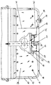
- the preferred embodiment of an embodiment of the invention shown in the single figure trained oil pan 10 of an internal combustion engine not otherwise shown comprises an inner plate 12 such that the oil pan 10 is double-walled.
- the Inner sheet 12 is equipped with a plurality of openings 14 which allow oil to pass through enable.
- the inner sheet 12 is multiple punctiform or linear with the Oil pan 10 connected, for example by means of welding points or lines 16.
- thermostatic Regulated cylinder valve 20 is arranged, which by a spring 22 against a bottom 24th the oil pan 10 is pressed, then the lubricating oil in the oil circuit from an interior 26 reaches the oil pump 18 via an annular suction opening 28.
- the located between the oil pan 10 and the inner panel 12 acts resting lubricating oil as a heat insulating layer and prevents undesired heat dissipation to the surroundings of the oil pan 10.
- an expansion element 30 presses the Cylinder valve 20 against the spring 22 in the direction of the oil pump 18, so that the original annular suction opening 28 partially or completely closed and instead one Ring opening 32 is effective so that lubricating oil from a space 34 between Oil pan 10 and inner wall 12 is sucked. This is in the right half of the figure of the cylinder valve 20 illustrated.
- the suction effect of the oil pump 18 therefore leads to an oil flow from the interior 26 through the plurality of openings 14, through the gap 34 and via the ring opening 32 to the oil pump 18, with a circulation of the Lubricating oil via the intermediate space 34 with a correspondingly high heat dissipation gives an outer surface of the oil pan 10 with which the flowing over the space 34 Lubricating oil is in heat-conducting contact.
- the intermediate space 34 near the cylinder valve 20 has an increased wall distance from the Inner sheet 12 from the outside of the oil pan 10.
- An oil drain plug 36 screwed to the oil pan 10 is of such length formed that they have an opening 38 in the inner plate 12 with its end substantially seals tightly. Through additional bulkheads 40 with openings 42 acceleration-related oil level changes limited.
- the oil pan 10 itself is preferably made of metal, in particular aluminum.
- the Inner sheet 12 can alternatively also be made from a plastic.
Landscapes
- Engineering & Computer Science (AREA)
- Mechanical Engineering (AREA)
- General Engineering & Computer Science (AREA)
- Lubrication Of Internal Combustion Engines (AREA)
- Lubrication Details And Ventilation Of Internal Combustion Engines (AREA)
Abstract
Description
Claims (15)
- Verfahren zum Regeln einer Kühlung von Schmieröl in einer Ölwanne einer Antriebsmaschine mit Druckumlaufschmierung, insbesondere Brennkraftmaschine, wobei das Öl in einer Ölwanne gesammelt wird, welche wenigstens teilweise doppelwandig ausgebildet ist,
dadurch gekennzeichnet, daß
bei erhöhtem Kühlbedarf das Schmieröl in dem doppelwandigen Bereich der Ölwanne zirkulierend gefördert wird und daß bei niedrigem Kühlbedarf das Schmieröl in dem doppelwandigen Bereich der Ölwanne im wesentlichen ruhend gehalten wird. - Verfahren nach Anspruch 1,
dadurch gekennzeichnet, daß
eine Ansaugöffnung einer Ölpumpe bei erhöhtem Kühlbedarf wenigstens teilweise mit dem doppelwandigen Bereich der Ölwanne und bei niedrigem Kühlbedarf mit einem Innenraum der Ölwanne verbunden wird. - Verfahren nach Anspruch 1,
dadurch gekennzeichnet, daß
bei erhöhtem Kühlbedarf das Schmieröl durch Öffnungen in einer inneren Wandung des doppelwandigen Bereichs der Ölwanne geleitet wird. - Verfahren nach Anspruch 1,
dadurch gekennzeichnet, daß
bei niedrigem Kühlbedarf der doppelwandige Bereich der Ölwanne von einer durch eine Ölpumpe erzeugte Zirkulation getrennt wird. - Brennkraftmaschine, insbesondere eines Kraftfahrzeuges, mit einer Ölwanne (10) zur Aufnahme von Schmieröl einer Druckumlaufschmierung, wobei die Ölwanne (10) wenigstens teilweise doppelwandig ausgebildet ist und in der Ölwanne (10) eine Ölpumpe (18) mit einer Ansaugöffnung (28) vorgesehen ist,
dadurch gekennzeichnet, daß
ein Thermostatventil (20) vorgesehen ist, welches in Abhängigkeit von einer Schmieröltemperatur wahlweise bei erhöhtem Kühlbedarf die Ansaugöffnung (28) mit dem doppelwandigen Bereich (34) der Ölwanne (10) derart verbindet, daß das Schmieröl wenigstens teilweise durch den doppelwandigen Bereich (34) der Ölwanne (10) zirkuliert, und bei niedrigem Kühlbedarf die Ansaugöffnung (28) von dem doppelwandigen Bereich (34) derart trennt, daß das Schmieröl im doppelwandigen Bereich (34) der Ölwanne (10) im wesentlichen von der durch die Ölpumpe (18) erzeugte Zirkulation abgetrennt ist. - Brennkraftmaschine nach Anspruch 5,
dadurch gekennzeichnet, daß
das Thermostatventil (20) ein Dehnstoffelement (30) aufweist. - Brennkraftmaschine nach Anspruch 5 oder 6,
dadurch gekennzeichnet, daß
das Thermostatventil (20) an einem Boden der Ölwanne (10) gegenüber der Ansaugöffnung (28) der Ölpumpe (18) angeordnet ist. - Brennkraftmaschine nach einem der Ansprüche 5 bis 7,
dadurch gekennzeichnet, daß
eine Feder (22), insbesondere Schraubenfeder, vorgesehen ist, welche das Thermostatventil (20) in Richtung Wandung der Ölwanne (10) mit Kraft beaufschlagt. - Brennkraftmaschine nach einem der Ansprüche 5 bis 8,
dadurch gekennzeichnet, daß
eine Innenwand (12) des doppelwandigen Bereiches (34) der Ölwanne (10) mit mehreren Öldurchtrittsöffnungen (14) versehen ist. - Brennkraftmaschine nach einem der Ansprüche 5 bis 9,
dadurch gekennzeichnet, daß
eine Innenwand (12) des doppelwandigen Bereiches (34) der Ölwanne (10) punktförmig oder linienförmig mit einer Außenwand der Ölwanne (10) verbunden ist. - Brennkraftmaschine nach einem der Ansprüche 5 bis 10,
dadurch gekennzeichnet, daß
ein Abstand zwischen einer Innenwand (12) und einer Außenwand des doppelwandigen Bereiches (34) der Ölwanne (10) im Bereich des Thermostatventiles (20) erhöht ist. - Brennkraftmaschine nach einem der Ansprüche 5 bis 11,
dadurch gekennzeichnet, daß
an einer Innenwandung (12) des doppelwandigen Bereiches (34) im Inneren (26) der Ölwanne (10) zusätzliche Schottwände (40) mit Öffnungen (42) vorgesehen sind. - Brennkraftmaschine nach einem der Ansprüche 5 bis 12,
dadurch gekennzeichnet, daß
das Thermostatventil (20) als Zylinderventil ausgebildet ist. - Brennkraftmaschine nach einem der Ansprüche 5 bis 13,
dadurch gekennzeichnet, daß
eine Innenwand (12) des doppelwandigen Bereiches (34) der Ölwanne (10) aus Kunststoff oder Metall, insbesondere Blech, oder einem Gußwerkstoff hergestellt ist. - Brennkraftmaschine nach einem der Ansprüche 5 bis 14,
dadurch gekennzeichnet, daß
im Boden der Ölwanne (10) eine Ölablaßschraube (26) vorgesehen ist, welche sich durch eine Innenwand (12) und eine Außenwand des doppelwandigen Bereiches (34) der Ölwanne (10) derart erstreckt, daß diese den Durchtritt (38) durch die Innenwand (12) abdichtet.
Applications Claiming Priority (2)
| Application Number | Priority Date | Filing Date | Title |
|---|---|---|---|
| DE19938688A DE19938688A1 (de) | 1999-08-14 | 1999-08-14 | Verfahren zum Regeln einer Kühlung von Schmieröl einer Brennkraftmaschine |
| DE19938688 | 1999-08-14 |
Publications (2)
| Publication Number | Publication Date |
|---|---|
| EP1077314A1 true EP1077314A1 (de) | 2001-02-21 |
| EP1077314B1 EP1077314B1 (de) | 2005-06-01 |
Family
ID=7918479
Family Applications (1)
| Application Number | Title | Priority Date | Filing Date |
|---|---|---|---|
| EP00114085A Expired - Lifetime EP1077314B1 (de) | 1999-08-14 | 2000-07-07 | Verfahren zum Regeln einer Kühlung von Schmieröl einer Brennkraftmaschine |
Country Status (3)
| Country | Link |
|---|---|
| EP (1) | EP1077314B1 (de) |
| AT (1) | ATE296945T1 (de) |
| DE (2) | DE19938688A1 (de) |
Cited By (1)
| Publication number | Priority date | Publication date | Assignee | Title |
|---|---|---|---|---|
| US10808582B2 (en) * | 2016-04-22 | 2020-10-20 | Audi Ag | Drive component for a motor vehicle, and motor vehicle |
Families Citing this family (1)
| Publication number | Priority date | Publication date | Assignee | Title |
|---|---|---|---|---|
| DE102011122419A1 (de) | 2011-12-24 | 2013-06-27 | Volkswagen Aktiengesellschaft | Eine zur Schmiermittelversorgung einer Brennkraftmaschine bestimmte Einrichtung mit einem Schmiermittelsammelbehälter sowie ein derart ausgestattetes Kraftfahrzeug |
Citations (6)
| Publication number | Priority date | Publication date | Assignee | Title |
|---|---|---|---|---|
| DE430795C (de) * | 1924-05-31 | 1926-06-23 | Maybach Motorenbau G M B H | OElumlauf- und Kuehleinrichtung bei Verbrennungskraftmaschinen von Motorfahrzeugen |
| FR2033173A1 (de) * | 1969-11-13 | 1970-12-04 | Citroen Sa | |
| US4258679A (en) * | 1978-04-22 | 1981-03-31 | Audi Nsu Auto Union Aktiengesellschaft | Device for controlling the lubricating oil temperature of a combustion engine having an oil container |
| US4296716A (en) * | 1978-06-03 | 1981-10-27 | Volkswagenwerk Aktiengesellschaft | Internal combustion engine for an automobile with a divided oil pan |
| DE4431105A1 (de) | 1994-09-01 | 1996-03-07 | Himmelsbach Johann | Verfahren zur Kühlung des Schmieröls von Verbrennungsmotoren mit Hilfe eines Isolierspaltes veränderlicher Wärmeleitfähigkeit |
| DE19729253A1 (de) * | 1997-07-09 | 1999-01-28 | Daimler Benz Ag | Ölwanne für eine Brennkraftmaschine |
Family Cites Families (6)
| Publication number | Priority date | Publication date | Assignee | Title |
|---|---|---|---|---|
| JPS5365536A (en) * | 1976-11-22 | 1978-06-12 | Toyota Motor Corp | Oil pan |
| AT372759B (de) * | 1977-04-05 | 1983-11-10 | Lenz Hans Peter Dipl Ing Dr Te | Fahrzeug-brennkraftmaschine mit einer in zwei kammern unterteilten oelwanne |
| DE3031362A1 (de) * | 1978-06-03 | 1982-04-01 | Volkswagenwerk Ag, 3180 Wolfsburg | Brennkraftmaschine fuer ein kraftfahrzeug mit einer unterteilten oelwanne |
| DE3142327A1 (de) * | 1981-10-24 | 1983-05-05 | Dr.Ing.H.C. F. Porsche Ag, 7000 Stuttgart | "oelwanne fuer eine brennkraftmaschine" |
| DE3235292C2 (de) * | 1982-09-23 | 1986-01-09 | Waldemar 8700 Würzburg Gontscharow | Brennkraftmaschine für ein Kraftfahrzeug |
| DE29706837U1 (de) * | 1997-04-16 | 1997-07-24 | Kunststofftechnik F.u.H. Riesselmann GmbH, 01458 Ottendorf-Okrilla | Ölwanne für Verbrennungsmotoren |
-
1999
- 1999-08-14 DE DE19938688A patent/DE19938688A1/de not_active Withdrawn
-
2000
- 2000-07-07 AT AT00114085T patent/ATE296945T1/de not_active IP Right Cessation
- 2000-07-07 DE DE50010438T patent/DE50010438D1/de not_active Expired - Lifetime
- 2000-07-07 EP EP00114085A patent/EP1077314B1/de not_active Expired - Lifetime
Patent Citations (6)
| Publication number | Priority date | Publication date | Assignee | Title |
|---|---|---|---|---|
| DE430795C (de) * | 1924-05-31 | 1926-06-23 | Maybach Motorenbau G M B H | OElumlauf- und Kuehleinrichtung bei Verbrennungskraftmaschinen von Motorfahrzeugen |
| FR2033173A1 (de) * | 1969-11-13 | 1970-12-04 | Citroen Sa | |
| US4258679A (en) * | 1978-04-22 | 1981-03-31 | Audi Nsu Auto Union Aktiengesellschaft | Device for controlling the lubricating oil temperature of a combustion engine having an oil container |
| US4296716A (en) * | 1978-06-03 | 1981-10-27 | Volkswagenwerk Aktiengesellschaft | Internal combustion engine for an automobile with a divided oil pan |
| DE4431105A1 (de) | 1994-09-01 | 1996-03-07 | Himmelsbach Johann | Verfahren zur Kühlung des Schmieröls von Verbrennungsmotoren mit Hilfe eines Isolierspaltes veränderlicher Wärmeleitfähigkeit |
| DE19729253A1 (de) * | 1997-07-09 | 1999-01-28 | Daimler Benz Ag | Ölwanne für eine Brennkraftmaschine |
Cited By (1)
| Publication number | Priority date | Publication date | Assignee | Title |
|---|---|---|---|---|
| US10808582B2 (en) * | 2016-04-22 | 2020-10-20 | Audi Ag | Drive component for a motor vehicle, and motor vehicle |
Also Published As
| Publication number | Publication date |
|---|---|
| DE19938688A1 (de) | 2001-02-15 |
| DE50010438D1 (de) | 2005-07-07 |
| ATE296945T1 (de) | 2005-06-15 |
| EP1077314B1 (de) | 2005-06-01 |
Similar Documents
| Publication | Publication Date | Title |
|---|---|---|
| EP0687584B1 (de) | Heizvorrichtung für Kraftfahrzeuge | |
| DE69800206T2 (de) | Hochbelastbarer viskose Ventilatorantrieb sowie Haltevorrichtung dafür | |
| DE4410249B4 (de) | Flüssigkeitskühlkreislauf für Verbrennungsmotoren | |
| DE602005004579T2 (de) | Multifunktionales Modul, Fahrzeug enthaltend ein solches Modul und Verfahren zur Herstellung eines solchen Moduls | |
| DE2349945A1 (de) | Antrieb fuer den kuehlventilator eines kraftfahrzeugmotors | |
| WO2009106159A1 (de) | Gekühltes gehäuse bestehend aus einem turbinengehäuse und einem lagergehäuse eines turboladers | |
| EP0361053A2 (de) | Heizvorrichtung für den Fahrgastraum eines eine flüssigkeitsgekühlte Brennkraftmaschine aufweisenden Kraftfahrzeuges | |
| DE3914154A1 (de) | Heizsystem, insbesondere fuer kraftfahrzeuge, mit einem verbrennungsmotor und einem heizgeraet | |
| DE3390405T1 (de) | Vorrichtung zur Verbesserung des Anlassens eines Motors | |
| AT2537U1 (de) | Kühlsystem für kraftfahrzeuge | |
| DE102006019086B4 (de) | Verfahren und Vorrichtung zur aktiven Öltemperierung bei Kraftfahrzeugen mit Verbrennungskraftmaschinen | |
| DE19823254C5 (de) | Brennkraftmaschine | |
| EP1077314A1 (de) | Verfahren zum Regeln einer Kühlung von Schmieröl einer Brennkraftmaschine | |
| EP2161479A1 (de) | Getriebe mit Getriebegehäuse und Verfahren zur Beeinflussung der Getriebeöltemperatur | |
| DE102019130719A1 (de) | Flüssigkeitspumpe | |
| DE10318711A1 (de) | Vorrichtung zum Antrieb der Kühlmittelpumpe einer Brennkraftmaschine | |
| DE112009000950T5 (de) | Integriertes Öl-Pumpen-, Wasser-Pumpen- und Ölkühler-Modul | |
| DE10225062A1 (de) | Kühlkonzept für Zylinderlaufbuchsen | |
| EP0658708A2 (de) | Anordnung zum Steuern der Temperatur eines hydraulischen Betriebsmittels für ein selbsttätig schaltendes Getriebe und einen hydrodynamischen Drehmomentwandler | |
| DE19500445A1 (de) | Verbrennungsmotor | |
| DE102023000333A1 (de) | Kühlkreislauf für einen elektrischen Antriebsstrang und Öl-Luft-Wärmetauscher | |
| DE102019133322A1 (de) | Antrieb mit einer Rotorwelleninnenkühlung eines Elektromotors sowie ein Kraftfahrzeug mit einem solchen Antrieb | |
| DE19725853C2 (de) | Heizgerät in Viskofluidbauweise | |
| DE102021100669B4 (de) | Motorbaugruppe | |
| DE10204592A1 (de) | Antriebseinheit |
Legal Events
| Date | Code | Title | Description |
|---|---|---|---|
| PUAI | Public reference made under article 153(3) epc to a published international application that has entered the european phase |
Free format text: ORIGINAL CODE: 0009012 |
|
| AK | Designated contracting states |
Kind code of ref document: A1 Designated state(s): AT BE CH CY DE DK ES FI FR GB GR IE IT LI LU MC NL PT SE |
|
| AX | Request for extension of the european patent |
Free format text: AL;LT;LV;MK;RO;SI |
|
| 17P | Request for examination filed |
Effective date: 20010821 |
|
| AKX | Designation fees paid |
Free format text: AT BE CH CY DE DK ES FI FR GB GR IE IT LI LU MC NL PT SE |
|
| 17Q | First examination report despatched |
Effective date: 20040524 |
|
| GRAP | Despatch of communication of intention to grant a patent |
Free format text: ORIGINAL CODE: EPIDOSNIGR1 |
|
| GRAS | Grant fee paid |
Free format text: ORIGINAL CODE: EPIDOSNIGR3 |
|
| GRAA | (expected) grant |
Free format text: ORIGINAL CODE: 0009210 |
|
| RAP1 | Party data changed (applicant data changed or rights of an application transferred) |
Owner name: VOIGT, DIETER, DIPL.-ING. |
|
| AK | Designated contracting states |
Kind code of ref document: B1 Designated state(s): AT BE CH CY DE DK ES FI FR GB GR IE IT LI LU MC NL PT SE |
|
| PG25 | Lapsed in a contracting state [announced via postgrant information from national office to epo] |
Ref country code: IT Free format text: LAPSE BECAUSE OF FAILURE TO SUBMIT A TRANSLATION OF THE DESCRIPTION OR TO PAY THE FEE WITHIN THE PRESCRIBED TIME-LIMIT;WARNING: LAPSES OF ITALIAN PATENTS WITH EFFECTIVE DATE BEFORE 2007 MAY HAVE OCCURRED AT ANY TIME BEFORE 2007. THE CORRECT EFFECTIVE DATE MAY BE DIFFERENT FROM THE ONE RECORDED. Effective date: 20050601 Ref country code: IE Free format text: LAPSE BECAUSE OF FAILURE TO SUBMIT A TRANSLATION OF THE DESCRIPTION OR TO PAY THE FEE WITHIN THE PRESCRIBED TIME-LIMIT Effective date: 20050601 Ref country code: NL Free format text: LAPSE BECAUSE OF FAILURE TO SUBMIT A TRANSLATION OF THE DESCRIPTION OR TO PAY THE FEE WITHIN THE PRESCRIBED TIME-LIMIT Effective date: 20050601 Ref country code: FI Free format text: LAPSE BECAUSE OF FAILURE TO SUBMIT A TRANSLATION OF THE DESCRIPTION OR TO PAY THE FEE WITHIN THE PRESCRIBED TIME-LIMIT Effective date: 20050601 Ref country code: GB Free format text: LAPSE BECAUSE OF FAILURE TO SUBMIT A TRANSLATION OF THE DESCRIPTION OR TO PAY THE FEE WITHIN THE PRESCRIBED TIME-LIMIT Effective date: 20050601 |
|
| REG | Reference to a national code |
Ref country code: GB Ref legal event code: FG4D Free format text: NOT ENGLISH |
|
| REG | Reference to a national code |
Ref country code: CH Ref legal event code: EP |
|
| REG | Reference to a national code |
Ref country code: IE Ref legal event code: FG4D Free format text: LANGUAGE OF EP DOCUMENT: GERMAN |
|
| PG25 | Lapsed in a contracting state [announced via postgrant information from national office to epo] |
Ref country code: LU Free format text: LAPSE BECAUSE OF NON-PAYMENT OF DUE FEES Effective date: 20050707 Ref country code: AT Free format text: LAPSE BECAUSE OF NON-PAYMENT OF DUE FEES Effective date: 20050707 Ref country code: CY Free format text: LAPSE BECAUSE OF FAILURE TO SUBMIT A TRANSLATION OF THE DESCRIPTION OR TO PAY THE FEE WITHIN THE PRESCRIBED TIME-LIMIT Effective date: 20050707 |
|
| REF | Corresponds to: |
Ref document number: 50010438 Country of ref document: DE Date of ref document: 20050707 Kind code of ref document: P |
|
| PG25 | Lapsed in a contracting state [announced via postgrant information from national office to epo] |
Ref country code: BE Free format text: LAPSE BECAUSE OF NON-PAYMENT OF DUE FEES Effective date: 20050731 Ref country code: LI Free format text: LAPSE BECAUSE OF NON-PAYMENT OF DUE FEES Effective date: 20050731 Ref country code: CH Free format text: LAPSE BECAUSE OF NON-PAYMENT OF DUE FEES Effective date: 20050731 Ref country code: MC Free format text: LAPSE BECAUSE OF NON-PAYMENT OF DUE FEES Effective date: 20050731 |
|
| PG25 | Lapsed in a contracting state [announced via postgrant information from national office to epo] |
Ref country code: GR Free format text: LAPSE BECAUSE OF FAILURE TO SUBMIT A TRANSLATION OF THE DESCRIPTION OR TO PAY THE FEE WITHIN THE PRESCRIBED TIME-LIMIT Effective date: 20050901 Ref country code: SE Free format text: LAPSE BECAUSE OF FAILURE TO SUBMIT A TRANSLATION OF THE DESCRIPTION OR TO PAY THE FEE WITHIN THE PRESCRIBED TIME-LIMIT Effective date: 20050901 Ref country code: DK Free format text: LAPSE BECAUSE OF FAILURE TO SUBMIT A TRANSLATION OF THE DESCRIPTION OR TO PAY THE FEE WITHIN THE PRESCRIBED TIME-LIMIT Effective date: 20050901 |
|
| PG25 | Lapsed in a contracting state [announced via postgrant information from national office to epo] |
Ref country code: ES Free format text: LAPSE BECAUSE OF FAILURE TO SUBMIT A TRANSLATION OF THE DESCRIPTION OR TO PAY THE FEE WITHIN THE PRESCRIBED TIME-LIMIT Effective date: 20050912 |
|
| PG25 | Lapsed in a contracting state [announced via postgrant information from national office to epo] |
Ref country code: PT Free format text: LAPSE BECAUSE OF FAILURE TO SUBMIT A TRANSLATION OF THE DESCRIPTION OR TO PAY THE FEE WITHIN THE PRESCRIBED TIME-LIMIT Effective date: 20051107 |
|
| NLV1 | Nl: lapsed or annulled due to failure to fulfill the requirements of art. 29p and 29m of the patents act | ||
| GBV | Gb: ep patent (uk) treated as always having been void in accordance with gb section 77(7)/1977 [no translation filed] |
Effective date: 20050601 |
|
| REG | Reference to a national code |
Ref country code: IE Ref legal event code: FD4D |
|
| REG | Reference to a national code |
Ref country code: CH Ref legal event code: PL |
|
| PLBE | No opposition filed within time limit |
Free format text: ORIGINAL CODE: 0009261 |
|
| STAA | Information on the status of an ep patent application or granted ep patent |
Free format text: STATUS: NO OPPOSITION FILED WITHIN TIME LIMIT |
|
| 26N | No opposition filed |
Effective date: 20060302 |
|
| EN | Fr: translation not filed | ||
| BERE | Be: lapsed |
Owner name: VOIGT, DIETER, DIPL.-ING. Effective date: 20050731 |
|
| PG25 | Lapsed in a contracting state [announced via postgrant information from national office to epo] |
Ref country code: FR Free format text: LAPSE BECAUSE OF NON-PAYMENT OF DUE FEES Effective date: 20050731 |
|
| PG25 | Lapsed in a contracting state [announced via postgrant information from national office to epo] |
Ref country code: FR Free format text: LAPSE BECAUSE OF NON-PAYMENT OF DUE FEES Effective date: 20050601 |
|
| PGFP | Annual fee paid to national office [announced via postgrant information from national office to epo] |
Ref country code: DE Payment date: 20140731 Year of fee payment: 15 |
|
| REG | Reference to a national code |
Ref country code: DE Ref legal event code: R119 Ref document number: 50010438 Country of ref document: DE |
|
| PG25 | Lapsed in a contracting state [announced via postgrant information from national office to epo] |
Ref country code: DE Free format text: LAPSE BECAUSE OF NON-PAYMENT OF DUE FEES Effective date: 20160202 |