EP1077338A2 - Methode und Schutzvorrichtung für eine Turbomaschinen- bürstendichtung - Google Patents
Methode und Schutzvorrichtung für eine Turbomaschinen- bürstendichtung Download PDFInfo
- Publication number
- EP1077338A2 EP1077338A2 EP00306672A EP00306672A EP1077338A2 EP 1077338 A2 EP1077338 A2 EP 1077338A2 EP 00306672 A EP00306672 A EP 00306672A EP 00306672 A EP00306672 A EP 00306672A EP 1077338 A2 EP1077338 A2 EP 1077338A2
- Authority
- EP
- European Patent Office
- Prior art keywords
- annular
- annular substrate
- gas turbine
- brush seal
- slot
- Prior art date
- Legal status (The legal status is an assumption and is not a legal conclusion. Google has not performed a legal analysis and makes no representation as to the accuracy of the status listed.)
- Withdrawn
Links
- 238000000034 method Methods 0.000 title claims abstract description 15
- 239000000758 substrate Substances 0.000 claims abstract description 120
- 238000009434 installation Methods 0.000 claims abstract description 21
- 239000000463 material Substances 0.000 claims description 33
- 239000007789 gas Substances 0.000 description 64
- 230000007704 transition Effects 0.000 description 9
- 239000002184 metal Substances 0.000 description 6
- 229920001971 elastomer Polymers 0.000 description 3
- 239000000806 elastomer Substances 0.000 description 3
- 229920003023 plastic Polymers 0.000 description 3
- 230000008602 contraction Effects 0.000 description 2
- 238000005452 bending Methods 0.000 description 1
- 239000011248 coating agent Substances 0.000 description 1
- 238000000576 coating method Methods 0.000 description 1
- 239000000567 combustion gas Substances 0.000 description 1
- 239000013536 elastomeric material Substances 0.000 description 1
- 238000005096 rolling process Methods 0.000 description 1
- 125000000391 vinyl group Chemical group [H]C([*])=C([H])[H] 0.000 description 1
- 229920002554 vinyl polymer Polymers 0.000 description 1
Images


Classifications
-
- F—MECHANICAL ENGINEERING; LIGHTING; HEATING; WEAPONS; BLASTING
- F16—ENGINEERING ELEMENTS AND UNITS; GENERAL MEASURES FOR PRODUCING AND MAINTAINING EFFECTIVE FUNCTIONING OF MACHINES OR INSTALLATIONS; THERMAL INSULATION IN GENERAL
- F16J—PISTONS; CYLINDERS; SEALINGS
- F16J15/00—Sealings
- F16J15/16—Sealings between relatively-moving surfaces
- F16J15/32—Sealings between relatively-moving surfaces with elastic sealings, e.g. O-rings
- F16J15/3284—Sealings between relatively-moving surfaces with elastic sealings, e.g. O-rings characterised by their structure; Selection of materials
- F16J15/3288—Filamentary structures, e.g. brush seals
-
- F—MECHANICAL ENGINEERING; LIGHTING; HEATING; WEAPONS; BLASTING
- F01—MACHINES OR ENGINES IN GENERAL; ENGINE PLANTS IN GENERAL; STEAM ENGINES
- F01D—NON-POSITIVE DISPLACEMENT MACHINES OR ENGINES, e.g. STEAM TURBINES
- F01D11/00—Preventing or minimising internal leakage of working-fluid, e.g. between stages
-
- F—MECHANICAL ENGINEERING; LIGHTING; HEATING; WEAPONS; BLASTING
- F02—COMBUSTION ENGINES; HOT-GAS OR COMBUSTION-PRODUCT ENGINE PLANTS
- F02C—GAS-TURBINE PLANTS; AIR INTAKES FOR JET-PROPULSION PLANTS; CONTROLLING FUEL SUPPLY IN AIR-BREATHING JET-PROPULSION PLANTS
- F02C7/00—Features, components parts, details or accessories, not provided for in, or of interest apart form groups F02C1/00 - F02C6/00; Air intakes for jet-propulsion plants
- F02C7/04—Air intakes for gas-turbine plants or jet-propulsion plants
- F02C7/05—Air intakes for gas-turbine plants or jet-propulsion plants having provisions for obviating the penetration of damaging objects or particles
-
- F—MECHANICAL ENGINEERING; LIGHTING; HEATING; WEAPONS; BLASTING
- F16—ENGINEERING ELEMENTS AND UNITS; GENERAL MEASURES FOR PRODUCING AND MAINTAINING EFFECTIVE FUNCTIONING OF MACHINES OR INSTALLATIONS; THERMAL INSULATION IN GENERAL
- F16J—PISTONS; CYLINDERS; SEALINGS
- F16J15/00—Sealings
- F16J15/16—Sealings between relatively-moving surfaces
- F16J15/32—Sealings between relatively-moving surfaces with elastic sealings, e.g. O-rings
- F16J15/3268—Mounting of sealing rings
Definitions
- the present invention generally relates to turbine subassemblies and, more particularly, is concerned with a turbine brush seal protection device and method.
- a gas turbine subassembly has a stator, a rotor and a brush seal of annular configuration attached to the stator.
- U.S. Pat. No. 5,613,829 to Wolfe et al. which is assigned to the same assignee as the present invention, discloses such a gas turbine subassembly.
- the brush seal is generally installed before the rotor at an intermediate stage in the turbine assembling process.
- the brush seal surrounds the rotor after installation of the rotor.
- bristles of the brush seal are exposed while workers perform a variety of operations including heavy lifting in close proximity to the brush seal bristles. It is not uncommon for workers to walk inside the turbine casing and, possibly, to walk on the brush seal during installation of various turbine components. Damage to the bristles of the brush seal has been observed in turbine installations.
- turbine brush seal protection device comprises: an annular substrate having an outer periphery and defining a slot open at said outer periphery, said slot for receiving a portion of an annular brush seal of a gas turbine subassembly during installation of a gas turbine such that said annular substrate at least partially covers the annular brush seal of the gas turbine subassembly; said annular substrate at said outer periphery and within said slot thereof being removably mountable to a stationary portion of the gas turbine subassembly.
- the annular substrate may have a substantially U-shaped configuration in cross-section and may be spaced from the portion of the annular brush seal of the gas turbine subassembly such that a space exists between said annular substrate and the portion of the annular brush seal of the gas turbine subassembly.
- the annular substrate may have a core comprised substantially of a first material and an enclosure comprised substantially of a second material and surrounding said core.
- the first material of said core of said annular substrate may be rigid and said second material of said enclosure of said annular substrate may be flexible.
- the first material of said core of said annular substrate may be metal and said second material of said enclosure of said annular substrate may be plastic.
- the annular substrate may have a substantially cylindrical configuration in cross-section.
- the annular substrate may be disposable about and in contact with the portion of the annular brush seal of the gas turbine subassembly.
- the annular substrate may be comprised substantially of an elastomeric material.
- the slot of said annular substrate may have an inner portion which substantially conforms to a shape of the portion of the annular brush seal of the gas turbine subassembly.
- the annular substrate may have a substantially strip configuration in cross-section, it may be disposed about and in contact with the portion of the annular brush seal of the gas turbine subassembly and may is comprise substantially metal.
- the slot of said annular substrate may have an inner portion which substantially conforms to a shape of the portion of the annular brush seal of the gas turbine subassembly.
- a method for protecting a turbine brush seal comprises the steps of: providing an annular substrate having an outer periphery and defining a slot open at the outer periphery; placing the annular substrate over a portion of an annular brush seal of a gas turbine subassembly such that the seal portion is disposed inside the slot of the annular substrate during installation of a gas turbine and the annular substrate at least partially covers the annular brush seal of the gas turbine subassembly; mounting the annular substrate at the outer periphery and within the slot thereof to a stationary portion of the gas turbine subassembly; and removing the annular substrate (60) from the stationary portion of the gas turbine subassembly before completion of installation of the gas turbine subassembly.
- the providing step may include providing the annular substrate with a substantially U-shaped configuration in cross-section.
- the providing step may include providing the annular substrate with a core comprised substantially of a first material and an enclosure comprised substantially of a second material and surrounding the core.
- the first material of the core of the annular substrate is rigid and the second material of the enclosure of the annular substrate is flexible.
- the providing step may include providing the annular substrate with a substantially cylindrical configuration in cross-section and the slot of the annular substrate with an inner portion which substantially conforms to a shape of the portion of the annular brush seal of the gas turbine subassembly.
- the providing step may include providing the annular substrate with a substantially strip configuration in cross-section and the slot of the annular substrate with an inner portion which substantially conforms to a shape of the portion of the annular brush seal of the gas turbine subassembly.
- the present invention provides a turbine brush seal protection device and method designed to satisfy the aforementioned need.
- the turbine brush seal protection device and method of the present invention protects the brush seal bristles from damage during installation of the components of the gas turbine subassembly.
- a turbine brush seal protection device comprises an annular substrate having an out periphery and defining a slot open at the outer periphery.
- the slot receives a portion of an annular brush seal of a gas turbine subassembly during installation of a gas turbine such that the annular substrate at least partially covers the annular brush seal of the gas turbine subassembly.
- the annular substrate at the outer periphery and within the slot thereof is removably mountable to a stationary portion of the gas turbine subassembly.
- the annular substrate in a first exemplary embodiment thereof has a substantially U-shaped configuration in cross-section and is spaced from the portion of the annular brush seal of the gas turbine subassembly such that a space exists between the annular substrate and the portion of the annular brush seal of the gas turbine subassembly.
- the annular substrate has a core comprised substantially of a first material and an enclosure comprised substantially of a second material and surrounding the core.
- the first material of the core of the annular substrate is rigid, such as metal, and the second material of the enclosure of the annular substrate is flexible, such as plastic.
- the annular substrate in a second exemplary embodiment thereof has a substantially cylindrical configuration in cross-section.
- the annular substrate is disposed about and in contact with the portion of the annular brush seal of the gas turbine subassembly.
- the annular substrate is comprised substantially of an elastomer material.
- the slot of the annular substrate has an inner portion which substantially conforms to the shape of the portion of the annular brush seal of the gas turbine subassembly.
- the annular substrate in a third exemplary embodiment thereof has a substantially strip configuration in cross-section and comprised substantially of metal.
- a turbine brush seal protection method comprises the steps of providing an annular substrate having an outer periphery and defining a slot open at the outer periphery, placing the annular substrate over a portion of an annular brush seal of a gas turbine subassembly such that the seal portion is disposed inside the slot of the annular substrate during installation of the gas turbine subassembly and the annular substrate at least partially covers the annular brush seal of the gas turbine subassembly, mounting the annular substrate at the inner periphery and within the slot thereof to a stationary portion of the gas turbine subassembly, and removing the annular substrate from the stationary portion of the gas turbine subassembly before completion of installation of the gas turbine subassembly.
- the providing step includes providing the annular substrate in one of the three exemplary embodiments described above.
- the subassembly 10 basically includes a stator 12, a rotor 14 and a brush seal 16.
- the subassembly 10 is part of a complete gas turbine (not shown) such as a combustion-type gas turbine which utilizes combustion gases to turn the rotor 14 or a steam-type gas turbine which utilizes steam to run the rotor 14.
- Gas turbines are used to power aircraft, ships, tanks, pipeline pumps, electric generators, etc.
- the subassembly 10 will be described hereinafter with particular reference to a power-plant gas turbine.
- the stator 12 has a generally longitudinally extending axis 18.
- the stator 12 includes an annular transition duct 20 having radially inner and outer stator portions 22 and 24 and a circumferential row of outlet guide vanes 26 (only two of which are shown in FIG. 1) whose radially inner ends are attached to the radially inner stator portion 22 and whose radially outer ends are attached to the radially outer stator portion 24.
- the stator 12 further includes a compressor stator casing 28 attached to the radially outer stator portion 24 of the transition duct 20 and three circumferential rows of compressor stator vanes 30 depending radially inward from the compressor stator casing 28.
- the direction of gas flow in this case air flow
- in the gas path of the gas turbine is from the compressor through the transition duct 20 to the combustor (not shown).
- the rotor 14 has generally-steady-state first and second rotation/load states.
- the first rotation/load state is a full-speed/full-load state and the second rotation/load state is a turning-gear/no-load state.
- the full-speed/full-load state is self explanatory.
- the turning-gear/no-load state describes a gas turbine rotor 14 which is being rotated at a low idle speed by an auxiliary motor through a turning gear. Gas turbine rotors used in ships, aircraft, etc., have their own various steady-state rotation/load states, as is known to the artisan.
- differential movement can be calculated (or measured) for a particular gas turbine, as can be done by those of ordinary skill in the art.
- the rotor 14 is generally coaxially aligned with and disposed radially within and spaced apart from the stator 12.
- the rotor 14 is rotatably attached to the stator 12 such as by rolling element bearings 34 (only one of which is shown in FIG. 1).
- the rotor 14 includes an outside surface 36 with longitudinally-extending and longitudinally-adjoining first and second circumferential portions 38 and 40.
- the first circumferential portion 38 has a manufactured first diameter which is generally constant over the longitudinal extent of the first circumferential portion 38.
- the second circumferential portion 40 has a manufactured second diameter which is everywhere smaller than the first diameter over the longitudinal extent of the second circumferential portion 40.
- the second circumferential portion 40 has a form of a groove in the outside surface 36 of the rotor 14.
- the second diameter may vary over the longitudinal extent of the groove.
- the rotor 14 has a transition rotor segment 42 associated with the transition duct 20, a compressor rotor segment 44 attached to the transition rotor segment 42, and three circumferential rows of compressor rotor blades 46 extending radially outward from the compressor rotor segment 44.
- the brush seal 16 has a generally annular configuration.
- the brush seal 16 is generally coaxially aligned with the stator 12.
- the brush seal 16 has an attached end 48 and a free end 50.
- the attached end 48 of the brush seal 16 is attached to the stator 12.
- the free end 50 of the brush seal 16 extends inwardly from the stator 12 to the rotor 14.
- the brush seal 16 includes an attachment ring 52.
- the attached end 48 is part of the attachment ring 52, as shown in FIGS. 1 and 2.
- the brush seal 16 comprises a plurality of bristles 54 which preferably are tilted in the direction of rotation 56 of the rotor 14, as best shown in FIG. 2.
- the free end 50 of the brush seal 16 (i.e., the collective free ends of the bristles 54 of the brush seal 16) is disposed in general line-to-line contact with the first circumferential portion 38 of the outside surface 36 of the rotor 14 when the rotor 14 is in the first rotation/load state.
- the predetermined differential radial and longitudinal thermal movement includes the free end 50 of the brush seal 16 that moves radially inward and longitudinally across the second circumferential portion 40 of the outside surface 36 of the rotor 14.
- line-to-line contact is meant that the free end 50 of the brush seal 16 just touches the first circumferential portion 38 of the outside surface 36 of the rotor 14 without any bending of (or other interference with) the brush seal 16.
- the stator 12 undergoes thermal contraction faster than the rotor 14 undergoes thermal contraction.
- the groove form of the second circumferential portion 40 of the outside surface 36 of the rotor 14 has a predetermined shape such that the free end 50 of the brush seal 16 does not contact the second circumferential portion 40 of the outside surface 36 of the rotor 14 during the transition.
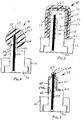
- the turbine brush seal protection device 58 can take the form of any one of three exemplary embodiments shown respectively in FIGS. 3, 4 and 5.
- the turbine brush seal protection device 58 basically includes an annular substrate 60.
- the annular substrate 60 has an outer periphery 62 and an inner periphery 64.
- the annular substrate 60 defines an interior slot 66 open at the outer periphery 62 and closed at the inner periphery 64.
- the slot 66 is for receiving a portion, such as the bristles 54, of the annular brush seal 16 of the gas turbine subassembly 10 during installation of the gas turbine such that the annular substrate 60 at least partially covers the annular brush seal 16 of the gas turbine subassembly 10.
- the annular substrate 60 at the outer periphery 62 and within the slot 66 thereof is removably mounted via an interference fit to a stationary portion 68 of the gas turbine subassembly 10.
- the stationary portion 68 of the gas turbine subassembly 10 may be the attachment ring 52 of the brush seal 16 or may be an annular diaphragm 68 of the brush seal 16 which is disposed on opposite sides of and is interfitted with the attachment ring 52 of the brush seal 16.
- the annular substrate 60 has a generally U-shaped configuration in cross-section.
- the annular substrate 60 is spaced from the portion of the annular brush seal 16 of the gas turbine subassembly 10 such that a space 70 exists between the annular substrate 60 and the portion of the annular brush seal 16.
- the annular substrate 60 has a core 72 comprised of a first material and an enclosure 74 comprised of a second material.
- the enclosure 74 surrounds the core 72.
- the first material of the core 72 is rigid and, preferably, is substantially metal.
- the core 72 may be, particularly, comprised of a string of staple-like elements or the like.
- the core 72 gives the annular substrate 60 strength.
- the second material of the enclosure 74 is flexible and, preferably, is plastic or may also be vinyl.
- Each of the core 72 and the enclosure 74 has a substantially U-shaped configuration in cross-section which generally conforms to the overall configuration of the annular substrate 60.
- the annular substrate 60 at the inner periphery 62 and along the enclosure 74 is, particularly, mounted to the annular diaphragm 68 of the annular brush seal 16.
- the annular substrate 60 within the slot 66 and along the enclosure 74 abuts against the attachment ring 52 of the annular brush seal 16.
- the annular substrate 60 has a substantially cylindrical configuration in cross-section.
- the annular substrate 60 is disposed against the portion of the annular brush seal 16 of the gas turbine subassembly 10 such that no space exists between the annular substrate 60 and the portion of the annular brush seal 16.
- the annular substrate 60 is comprised substantially of an elastomer material.
- the annular substrate 60 is in the form of an encapsulate with the elastomer material being removable.
- the slot 66 of the annular substrate 60 has an inner portion 66a and an outer portion 66b.
- the inner portion 66a of the slot 66 substantially conforms to a shape of the portion of the annular brush seal 16, such as to a collection of bristles 54 of the brush seal 16.
- the outer portion 66b of the slot 66 substantially conforms to a shape of a portion of the attachment ring 52 of the brush seal 16.
- the annular substrate 60 within the slot 66 is, particularly, mounted to the attachment ring 52 of the brush seal 16.
- the annular substrate 60 has a substantially strip configuration in cross-section.
- the annular substrate 60 is disposed about and in contact with the portion of the annular brush seal 16 of the gas turbine subassembly 10 such that no space exists between the annular substrate 60 and the portion of the annular brush seal 16.
- the annular substrate 60 is comprised substantially of metal.
- the slot 66 of the annular substrate 60 has an inner portion 66a and an outer portion 66b. The inner portion 66a of the slot 66 conforms substantially to the shape of the portion of the annular brush seal 16, such as to the collection of bristles 54 of the brush seal 16.
- the outer portion 66b of the slot 66 substantially conforms to a shape of a portion of the attachment ring 52 of the brush seal 16.
- the annular substrate 60 at the outer portion 66b of the slot 66 covers a greater portion of the attachment ring 52 in the third exemplary embodiment than in the second exemplary embodiment thereof.
- the annular substrate 60 within the slot 66 is, particularly, mounted to the attachment ring 52 of the brush seal 16, such as by being tacked in place.
- the turbine brush seal protection method includes the steps of providing the annular substrate 60 having the above-described outer periphery 62 and defining the slot 66 open at the outer periphery 62, placing the portion, including the bristles 54, of the annular brush seal 16 of the gas turbine subassembly 10 inside the slot 66 of the annular substrate 60 during installation of the gas turbine such that the annular substrate 60 at least partially covers the annular brush seal 16 of the gas turbine subassembly 10, mounting the annular substrate 60 at the inner periphery 62 and within the slot 66 to the stationary portion 68 of the gas turbine subassembly 10, and removing the annular substrate 60 from the stationary portion 68 of the gas turbine subassembly 10 before completion of the installation of the rotor 14 of the gas turbine subassembly 10.
- the providing step includes providing the annular substrate 60 with the substantially U-shaped configuration in cross-section and the annular substrate 60 with the core 72 comprised substantially of the first material and the enclosure 74 comprised substantially of the second material and surrounding the core 72 and the first material of the core 72 of the annular substrate 60 being rigid and the second material of the enclosure 74 of the annular substrate 60 being flexible, as shown in FIG. 3.
- the providing step includes providing the annular substrate 60 with the cylindrical configuration in cross-section and the slot 66 of the annular substrate 60 with the inner portion 66a which substantially conforms to the shape of the portion of the annular brush seal 16 of the gas turbine subassembly 10.
- the providing step in the third exemplary embodiment, includes providing the annular substrate 60 with a strip configuration in cross-section and the slot 66 of the annular substrate 60 with an inner portion 66a which substantially conforms to the shape of the portion of the annular brush seal 16 of the gas turbine subassembly 10.
Landscapes
- Engineering & Computer Science (AREA)
- General Engineering & Computer Science (AREA)
- Mechanical Engineering (AREA)
- Chemical & Material Sciences (AREA)
- Combustion & Propulsion (AREA)
- Turbine Rotor Nozzle Sealing (AREA)
- Sealing Devices (AREA)
Applications Claiming Priority (2)
| Application Number | Priority Date | Filing Date | Title |
|---|---|---|---|
| US376835 | 1989-07-06 | ||
| US09/376,835 US6206629B1 (en) | 1999-08-18 | 1999-08-18 | Turbine brush seal protection device and method |
Publications (2)
| Publication Number | Publication Date |
|---|---|
| EP1077338A2 true EP1077338A2 (de) | 2001-02-21 |
| EP1077338A3 EP1077338A3 (de) | 2003-08-20 |
Family
ID=23486716
Family Applications (1)
| Application Number | Title | Priority Date | Filing Date |
|---|---|---|---|
| EP00306672A Withdrawn EP1077338A3 (de) | 1999-08-18 | 2000-08-04 | Methode und Schutzvorrichtung für eine Turbomaschinen- bürstendichtung |
Country Status (4)
| Country | Link |
|---|---|
| US (1) | US6206629B1 (de) |
| EP (1) | EP1077338A3 (de) |
| JP (1) | JP2001107744A (de) |
| KR (1) | KR20010039818A (de) |
Cited By (3)
| Publication number | Priority date | Publication date | Assignee | Title |
|---|---|---|---|---|
| EP1298367A3 (de) * | 2001-09-28 | 2004-01-28 | Eagle Industry Co., Ltd. | Bürstendichtung |
| US6799766B2 (en) | 2002-01-25 | 2004-10-05 | Cross Manufacturing Company (1938) Limited | Brush seal element |
| EP3147049B1 (de) * | 2015-09-28 | 2021-11-17 | Raytheon Technologies Corporation | Verfahren zur herstellung eines tangentialen bordseitigen injektors |
Families Citing this family (11)
| Publication number | Priority date | Publication date | Assignee | Title |
|---|---|---|---|---|
| US6508624B2 (en) | 2001-05-02 | 2003-01-21 | Siemens Automotive, Inc. | Turbomachine with double-faced rotor-shroud seal structure |
| US6550777B2 (en) | 2001-06-19 | 2003-04-22 | General Electric Company | Split packing ring segment for a brush seal insert in a rotary machine |
| US6652231B2 (en) * | 2002-01-17 | 2003-11-25 | General Electric Company | Cloth seal for an inner compressor discharge case and methods of locating the seal in situ |
| US6644668B1 (en) | 2002-06-13 | 2003-11-11 | General Electric Company | Brush seal support |
| WO2004077711A2 (en) * | 2003-02-24 | 2004-09-10 | Hawe William R | System, method and apparatus for ascertaining a dynamic attribute of a system |
| US8469656B1 (en) | 2008-01-15 | 2013-06-25 | Siemens Energy, Inc. | Airfoil seal system for gas turbine engine |
| US8414254B2 (en) * | 2008-02-18 | 2013-04-09 | United Technologies Corporation | Sealing assembly for a turbine engine |
| US8398090B2 (en) | 2010-06-09 | 2013-03-19 | General Electric Company | Spring loaded seal assembly for turbines |
| WO2012170750A2 (en) | 2011-06-07 | 2012-12-13 | Sealeze, A Unit Of Jason Incorporated | Brush seal cover assembly |
| US9587505B2 (en) | 2013-12-05 | 2017-03-07 | General Electric Company | L brush seal for turbomachinery application |
| US9322287B2 (en) | 2014-06-03 | 2016-04-26 | General Electric Company | Brush seal for turbine |
Citations (1)
| Publication number | Priority date | Publication date | Assignee | Title |
|---|---|---|---|---|
| US5613829A (en) | 1996-05-03 | 1997-03-25 | General Electric Company | Gas turbine subassembly having a brush seal |
Family Cites Families (4)
| Publication number | Priority date | Publication date | Assignee | Title |
|---|---|---|---|---|
| US2984053A (en) * | 1951-07-14 | 1961-05-16 | Osborn Mfg Co | Brush and brush material |
| DE3514382C1 (de) * | 1985-04-20 | 1986-06-12 | Motoren Turbinen Union | Buerstendichtung |
| US5556172A (en) * | 1994-05-11 | 1996-09-17 | Technetics Corporation | Brush seal bristle cutting method |
| DE19645163C2 (de) * | 1996-11-02 | 2000-10-05 | Mtu Muenchen Gmbh | Bürstendichtung für Rotor-Stator-Anordnung |
-
1999
- 1999-08-18 US US09/376,835 patent/US6206629B1/en not_active Expired - Fee Related
-
2000
- 2000-08-04 EP EP00306672A patent/EP1077338A3/de not_active Withdrawn
- 2000-08-17 KR KR1020000047373A patent/KR20010039818A/ko not_active Withdrawn
- 2000-08-17 JP JP2000247157A patent/JP2001107744A/ja not_active Withdrawn
Patent Citations (1)
| Publication number | Priority date | Publication date | Assignee | Title |
|---|---|---|---|---|
| US5613829A (en) | 1996-05-03 | 1997-03-25 | General Electric Company | Gas turbine subassembly having a brush seal |
Cited By (4)
| Publication number | Priority date | Publication date | Assignee | Title |
|---|---|---|---|---|
| EP1298367A3 (de) * | 2001-09-28 | 2004-01-28 | Eagle Industry Co., Ltd. | Bürstendichtung |
| US6799766B2 (en) | 2002-01-25 | 2004-10-05 | Cross Manufacturing Company (1938) Limited | Brush seal element |
| EP3147049B1 (de) * | 2015-09-28 | 2021-11-17 | Raytheon Technologies Corporation | Verfahren zur herstellung eines tangentialen bordseitigen injektors |
| US11459905B2 (en) | 2015-09-28 | 2022-10-04 | Raytheon Technologies Corporation | Duct with additive manufactured seal |
Also Published As
| Publication number | Publication date |
|---|---|
| US6206629B1 (en) | 2001-03-27 |
| EP1077338A3 (de) | 2003-08-20 |
| JP2001107744A (ja) | 2001-04-17 |
| KR20010039818A (ko) | 2001-05-15 |
Similar Documents
| Publication | Publication Date | Title |
|---|---|---|
| US6206629B1 (en) | Turbine brush seal protection device and method | |
| CA2202952C (en) | Gas turbine subassembly having a brush seal | |
| EP2474708B1 (de) | Luftdichtungsanordnung und zugehöriges Montageverfahren | |
| CN107100682B (zh) | 用于燃气涡轮发动机壳空隙的原地修理的系统及方法 | |
| EP3318785B1 (de) | Segmentierte ringdichtung | |
| EP3121386B1 (de) | Gebläseschaufelplattform mit versteifungsmerkmal, entsprechende baugruppe und verfahren | |
| US10088049B2 (en) | Thermally protected seal assembly | |
| EP1548238B1 (de) | Verfahren zur Optimierung von Radialspalten eines Gehäuses eines Turbinentriebwerks | |
| US10788131B2 (en) | Face seal arrangement | |
| EP3623790B1 (de) | Eingebettete nichtintrusive spannungsmesssystemsonde | |
| US4244221A (en) | Removable instrumentation probe | |
| US6887038B2 (en) | Methods and apparatus to facilitate sealing between rotating turbine shafts | |
| EP3542951B1 (de) | Gebläseschaufelreparaturarmatur und verfahren zur reparatur | |
| EP3450696A1 (de) | Segmentierter kanal mit tragflächengeometrie | |
| EP3358149A1 (de) | Entlüftungsventil mit neutral- oder schliessvorspannung | |
| EP3910166B1 (de) | Radialdichtungsanordnung | |
| US20160377092A1 (en) | Cantilevered stator vane and stator assembly for a rotary machine | |
| EP3461997A1 (de) | Vorrichtung, zugehöriges gasturbinentriebwerk und verfahren zum zusammenbau | |
| CN103573416B (zh) | 密封件 | |
| EP2984318B1 (de) | Gasturbinenmotordichtung | |
| EP3760841B1 (de) | Mehrzweckdrehsicherungssperrbolzen | |
| EP3971389A1 (de) | Antiwirbelrohrhaltering und bohrkorb | |
| EP3323998B1 (de) | Innendeckbandsegment sowie zugehöriges deckband und gasturbinenmotor | |
| EP3470685A1 (de) | Spaltverschluss-schleissrücken | |
| EP4328419B1 (de) | Abgasanordnung zur spülung einer gondelhöhle eines antriebssystems |
Legal Events
| Date | Code | Title | Description |
|---|---|---|---|
| PUAI | Public reference made under article 153(3) epc to a published international application that has entered the european phase |
Free format text: ORIGINAL CODE: 0009012 |
|
| AK | Designated contracting states |
Kind code of ref document: A2 Designated state(s): AT BE CH CY DE DK ES FI FR GB GR IE IT LI LU MC NL PT SE |
|
| AX | Request for extension of the european patent |
Free format text: AL;LT;LV;MK;RO;SI |
|
| PUAL | Search report despatched |
Free format text: ORIGINAL CODE: 0009013 |
|
| AK | Designated contracting states |
Designated state(s): AT BE CH CY DE DK ES FI FR GB GR IE IT LI LU MC NL PT SE |
|
| AX | Request for extension of the european patent |
Extension state: AL LT LV MK RO SI |
|
| AKX | Designation fees paid | ||
| REG | Reference to a national code |
Ref country code: DE Ref legal event code: 8566 |
|
| STAA | Information on the status of an ep patent application or granted ep patent |
Free format text: STATUS: THE APPLICATION IS DEEMED TO BE WITHDRAWN |
|
| 18D | Application deemed to be withdrawn |
Effective date: 20040521 |